
Control robot arms with inverse and forward kinematics, converting X/Y/Z positions into joint motion and reporting end-effector location.
How to add the Inverse Kinematic Arm robot skill
- Load the most recent release of ARC (Get ARC).
- Press the Project tab from the top menu bar in ARC.
- Press Add Robot Skill from the button ribbon bar in ARC.
- Choose the Servo category tab.
- Press the Inverse Kinematic Arm icon to add the robot skill to your project.
Don't have a robot yet?
Follow the Getting Started Guide to build a robot and use the Inverse Kinematic Arm robot skill.
How to use the Inverse Kinematic Arm robot skill
This manual will walk you through everything you need to know to set up and use the Synthiam ARC Inverse Kinematics Robot Skill. No prior robotics experience required -- we explain every step in plain language.
Table of Contents
- What Does This Thing Actually Do?
- Words You Need to Know First
- Understanding the Main Window
- Setting Up Your Robot Arm (Configuration)
- Testing Your Setup (Do This Before Anything Else)
- Moving the Arm With Code
- Real-World Examples
- Troubleshooting and Tips
What Does This Thing Actually Do?
This robot skill lets you control a robot arm by telling it where you want the hand (called the "end effector") to go, and the software figures out how to bend each joint to get there.
There are two modes:
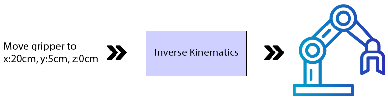
Inverse Kinematics (You Tell It Where to Go)
- You type in a position using X, Y, and Z numbers (measured in centimeters).
- The software calculates how each joint needs to move.
- The arm moves to that position automatically.
Think of it like this: You point at a spot on a table and say "reach there." Your brain automatically figures out how to bend your shoulder, elbow, and wrist. That is inverse kinematics.
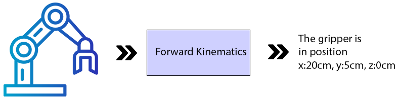
Forward Kinematics (It Tells You Where It Is)
- You move the arm's joints yourself (by hand or with other software).
- The software calculates where the hand ended up in 3D space.
- It displays the X, Y, and Z position of the hand.
Think of it like this: You close your eyes, move your arm randomly, then open your eyes and see where your hand is. That is forward kinematics.
Words You Need to Know First
Before we go further, here are some terms that will come up a lot. Read through these so the rest of the manual makes sense.
End Effector
This is whatever tool or device is attached to the tip of the robot arm. Think of it as the robot's "hand."
Examples:
- A gripper (like fingers that open and close)
- A pen or brush
- A surgical tool
- A suction cup
The end effector is the part that actually does the work.
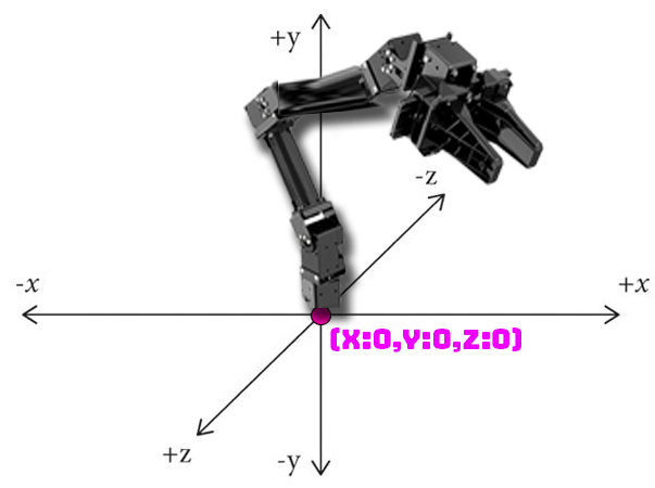
X, Y, and Z Coordinates
These are three numbers that describe a position in 3D space. All measurements are in centimeters (cm).
Think of it like giving directions:
- X = How far left or right (like sliding your hand along a table)
- Y = How far up or down (like raising your hand in the air)
- Z = How far forward or backward (like reaching away from your body)
The exact meaning of X, Y, and Z depends on how your robot arm is mounted:
- Arm on a table: X is left/right, Y is up/down, Z is forward/back
- Arm on a humanoid shoulder: The orientation may be rotated
Servo
A servo is a small motor that moves to a specific angle when you tell it to. Robot arms use servos at each joint to bend and rotate. Think of them like the muscles in your arm.
Joint
A joint is a point where two parts of the arm connect and can move. Your arm has joints at your shoulder, elbow, and wrist. A robot arm works the same way.
There are two types of joints in this software:
- Rotation Joint -- Spins around like a lazy Susan. Usually used at the base of the arm so it can turn left and right.
- Lever Joint -- Bends up and down like your elbow. Used for the rest of the arm.
Bone
A bone is the rigid section between two joints. Just like the bones in your arm, these are the parts that don't bend.
EZB
The EZB is the hardware controller board that the servos plug into. This software requires all servos to be connected to EZB Index #0 (the first controller).
Understanding the Main Window
When you open the robot skill, you will see the main control window. Here is what each part does:
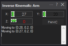
X Value Box
- In Inverse Kinematics mode: Type a number here to move the end effector left or right. The number is in centimeters, measured from the center of the robot base.
- In Forward Kinematics mode: This shows you where the end effector currently is (left/right).
Y Value Box
- In Inverse Kinematics mode: Type a number here to move the end effector up or down. The number is in centimeters, measured from the ground or mounting surface.
- In Forward Kinematics mode: This shows you where the end effector currently is (up/down).
Z Value Box
- In Inverse Kinematics mode: Type a number here to move the end effector forward or backward. The number is in centimeters, measured from the center of the base.
- In Forward Kinematics mode: This shows you where the end effector currently is (forward/back).
The Panic Button
This is your emergency stop. Press this button if:
- The arm gets stuck or jammed
- The arm is trying to reach somewhere it physically cannot
- The arm hits something
- The servos are making straining or buzzing noises
What it does: It immediately releases all the servos so they stop trying to move. The arm will go limp.
Setting Up Your Robot Arm (Configuration)
This is the most important part. You need to tell the software exactly how your robot arm is built so it can calculate movements correctly.
Step 1: Open the Configuration Window
Click the configuration/settings button in the robot skill to open the configuration window.
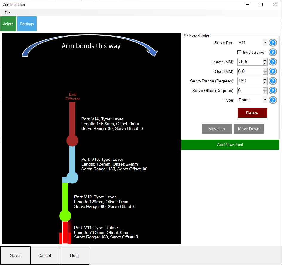
Step 2: Add Your Joints
You need to add one entry for each joint in your robot arm, starting from the base and working up to the end effector. For each joint, you will fill in the following fields:
A. Choose the servo Port
This is the port number on the EZB board where this joint's servo is plugged in.
- Look at your EZB board
- Find which port the servo wire is plugged into
- Enter that port number
B. Set the Joint Type
Choose one of these:
- Rotation -- Use this for the base joint (the one that spins the whole arm left and right)
- Lever -- Use this for all other joints (the ones that bend up and down like an elbow)
Rule of thumb: The first joint is usually Rotation. Everything after that is usually Lever.
C. Measure and Enter the Length (in millimeters)
This is the most critical measurement. It is the distance from the center of this joint's shaft to the center of the next joint's shaft.
How to measure:
- Look at the joint -- find the center of the shaft (the pin it rotates around)
- Look at the next joint -- find the center of that shaft
- Measure the distance between them in millimeters (mm)
For the last joint (end effector): Measure from the center of its rotation shaft to the very tip of the tool (like the tip of a gripper).
Important: These measurements need to be accurate. If they are off, the arm will miss its targets. Use a digital caliper if you have one. If you have CAD files for your arm, get the measurements from there.
Here is an example showing how to measure the joints on a Robotis Open Manipulator X:
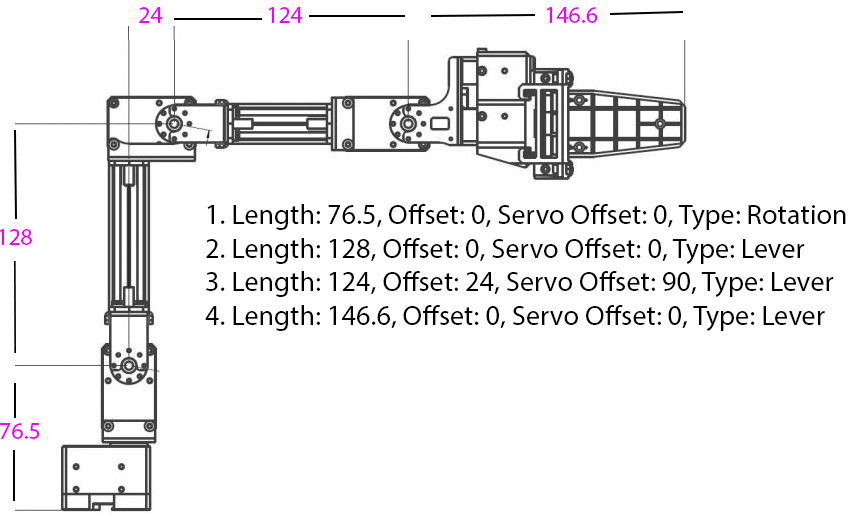
And here is how each joint and offset maps out visually:
D. Enter the Offset (in millimeters)
This is how far this joint is shifted to the side compared to the joint below it.
- If the joint is directly above the previous joint: enter 0
- If the joint is shifted to the left or right: measure that distance and enter it
Most simple robot arms have an offset of 0 for all joints.
E. Set the servo Range (in degrees)
This tells the software how far the servo can move from its center position.
- Standard 180-degree hobby servo: Enter 90 (it can move 90 degrees in each direction from center)
- 360-degree servo: Enter 180
- If your servo has a different range, divide its total range by 2 and enter that number
This prevents the software from trying to move the servo past its physical limits.
F. Set the servo Offset (in degrees)
This compensates for how the servo is mounted on the arm.
- If the servo is mounted straight (no rotation): enter 0
- If the servo is mounted sideways (rotated 90 degrees): enter 90
- If you are not sure, start with 0 and adjust later if the arm moves incorrectly
G. Check "Invert Servo" If Needed
If a joint moves in the opposite direction from what you expect (for example, you tell it to go up and it goes down), check this box to reverse it.
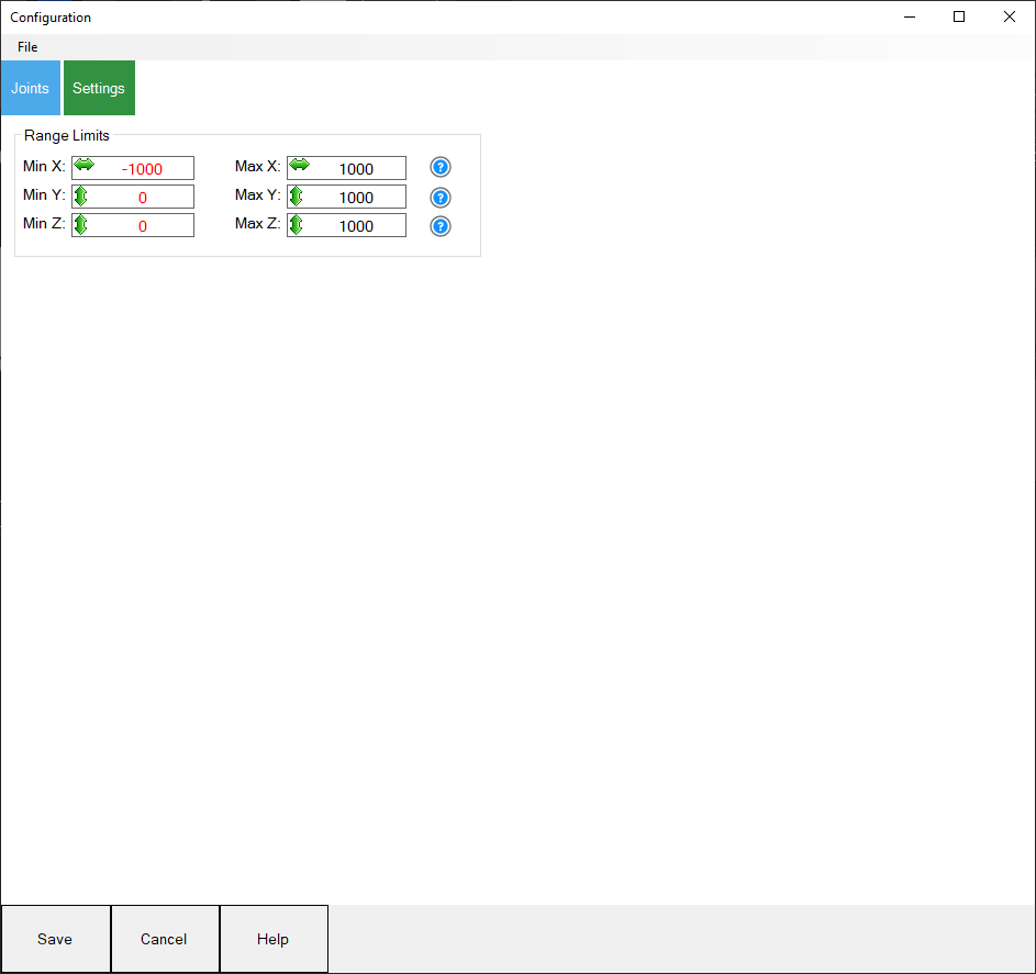
Step 3: Set Range Limits
To protect your arm and servos, set limits on how far the end effector can move:
- Set the minimum and maximum X values
- Set the minimum and maximum Y values
- Set the minimum and maximum Z values
This creates a safe "box" that the arm will stay inside.
Step 4: Save Your Configuration
- Go to the File menu in the configuration window
- Save your configuration
- It will be saved as a
.kinematicfile in the ARC documents folder
You can load this file later to avoid re-entering everything. You can also share it with others who have the same robot arm.
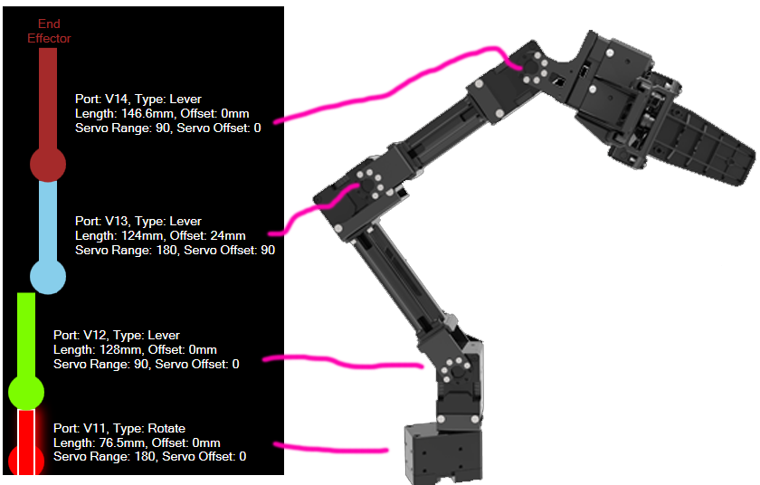
Testing Your Setup (Do This Before Anything Else)
Do NOT skip this section. If your configuration is wrong and you try to use inverse kinematics right away, the arm could move to unexpected positions and damage itself or nearby objects.
*Note: This section assumes you have correctly added measured joint lengths into the Inverse Kinematics robot skill configuration.
Step 1: Move the Arm to a Known Position
Before testing, move all servos to a known angle (like 90 degrees or 180 degrees) using one of these methods:
- Use a servo robot skill to set each servo position manually
- Write a simple script that sets each servo to a specific angle
The example below shows a robot arm moved into known 180-degree positions so the forward kinematics can be verified safely:
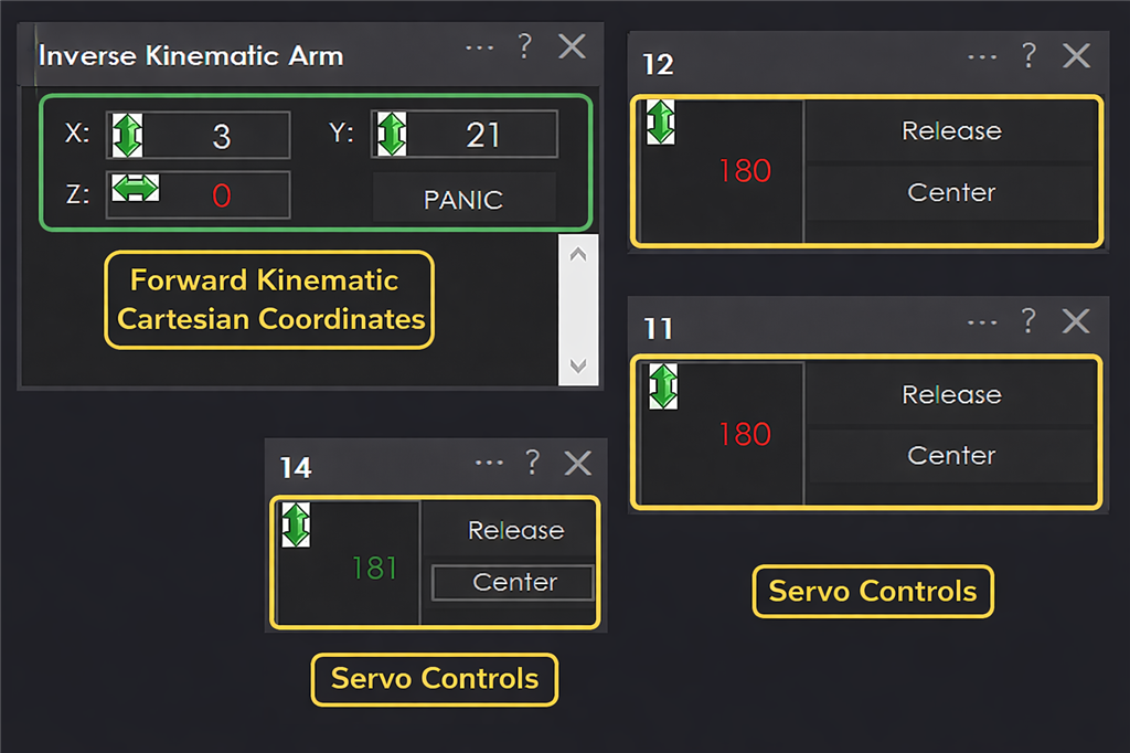
Step 2: Check Forward Kinematics
- Look at the X, Y, and Z values displayed in the main window
- These numbers should roughly match where the end effector actually is in real life
- If the numbers seem way off, your configuration has an error -- go back and check your measurements
Step 3: Move Joints One at a Time
- Using a servo robot skill, move one servo at a time by small amounts
- Watch the X, Y, Z values update in the main window
- Verify that:
- Moving the base rotation changes the X value
- Moving lever joints changes Y and Z values
- The numbers make sense compared to what you see
Step 4: Try Inverse Kinematics (Carefully)
Once forward kinematics looks correct:
- Note the current X, Y, Z values from forward kinematics
- Type those same values into the inverse kinematics fields
- The arm should stay in roughly the same position (since you are telling it to go where it already is)
- Gradually change the values by small amounts (1-2 cm at a time)
- Watch the arm move and verify it goes where expected
If Something Goes Wrong
- Press the Panic button immediately to release all servos
- Go back to the configuration and double-check your measurements
- Common problems:
- Wrong bone length measurements
- Servo offset angles are incorrect
- "Invert Servo" needs to be toggled
- Joint type is wrong (Lever vs. Rotation)
Moving the Arm With Code
Once your arm is configured and tested, you can control it with code using the ControlCommand function.
The Basic Command
ControlCommand("Inverse Kinematics Arm", "MoveTo", x, y, z);
Replace x, y, and z with the position you want the end effector to move to (in centimeters).
Step-by-Step Example
Let's say you want to move the arm so the gripper is:
- Centered (X = 0)
- 10 cm above the ground (Y = 10)
- 15 cm forward (Z = 15)
Here is what you do:
- Open a script editor in ARC
- Type this code:
ControlCommand("Inverse Kinematics Arm", "MoveTo", 0, 10, 15);
- Run the script
- The arm will move to that position
Moving to Multiple Positions
To move to several positions one after another, add sleep() between each move so the arm has time to finish moving:
// Move to position 1
ControlCommand("Inverse Kinematics Arm", "MoveTo", 0, 10, 15);
sleep(2000);  // Wait 2 seconds

// Move to position 2
ControlCommand("Inverse Kinematics Arm", "MoveTo", 5, 15, 10);
sleep(2000);  // Wait 2 seconds

// Move to position 3
ControlCommand("Inverse Kinematics Arm", "MoveTo", -5, 8, 20);
Real-World Examples
Example 1: Pick Up an Object Using a Camera
What this does: The robot sees an object through a camera, moves to it, and picks it up with a gripper.
What you need:
- A robot arm with a gripper as the end effector
- A camera mounted above the area the arm can reach
- The Camera Device robot skill set up and tracking objects
How it works, step by step:
- The camera spots an object and records its position (in pixels)
- The code converts the camera's pixel position to centimeters the robot understands
- The arm opens the gripper
- The arm moves to the object's location
- The arm closes the gripper to grab the object
The code (paste this into the Camera Device "Tracking Start" JavaScript section):
// Step 1: Open the gripper by moving the gripper servo
Servo.setPosition(v15, 260);

// Step 2: Wait 1 second for the gripper to fully open
sleep(1000);

// Step 3: Convert the camera's X pixel position to robot X centimeters
// The camera image is 320 pixels wide
// We map that to -20cm to +20cm for the robot
var x = Utility.map(
  getVar("$CameraObjectX"),
  0,      // Camera left edge (pixels)
  320,    // Camera right edge (pixels)
  -20,    // Robot left limit (cm)
  20      // Robot right limit (cm)
);

// Step 4: Convert the camera's Y pixel position to robot Z centimeters
// The camera image is 240 pixels tall
// We map that to 30cm to 15cm for the robot (forward/back)
var z = Utility.map(
  getVar("$CameraObjectY"),
  0,      // Camera top edge (pixels)
  240,    // Camera bottom edge (pixels)
  30,     // Robot far position (cm)
  15      // Robot near position (cm)
);

// Step 5: Move the arm to the object
// Y is set to 1 (close to the ground/table surface)
ControlCommand("Inverse Kinematics Mover", "MoveTo", x, 1, z);

// Step 6: Wait 2 seconds for the arm to reach the position
sleep(2000);

// Step 7: Close the gripper to grab the object
Servo.setPosition(v15, 190);
Things you will need to adjust for your setup:
v15-- Change this to whatever servo port your gripper is connected to260and190-- These are the open and close positions for the gripper. Your gripper will have different values.320and240-- These are the camera resolution. Change them if your camera is different.-20, 20, 30, 15-- These are the robot arm's reach limits. Adjust them based on where your arm and camera are positioned.- The Y value of
1-- Adjust this based on how high the objects are.
Example 2: Track a Moving Object With the Camera
What this does: The robot arm continuously follows an object that the camera sees, moving in real time to track it.
The code (paste this into the Camera Device "Tracking Start" script):
while (true) {

  // Convert camera X position to robot X (left/right rotation)
  var x = Utility.map(
    getVar("$CameraObjectX"),
    0,      // Camera left edge
    320,    // Camera right edge
    -20,    // Robot left limit (cm)
    20      // Robot right limit (cm)
  );

  // Convert camera Y position to robot Y (up/down)
  var y = Utility.map(
    getVar("$CameraObjectY"),
    0,      // Camera top edge
    240,    // Camera bottom edge
    35,     // Robot top limit (cm)
    5       // Robot bottom limit (cm)
  );

  // Convert detected object size to robot Z (distance)
  // Bigger object in camera = closer to camera = different Z position
  var z = Utility.map(
    getVar("$CameraObjectWidth"),
    40,     // Small object (far away)
    100,    // Big object (close up)
    20,     // Robot far position (cm)
    30      // Robot near position (cm)
  );

  // Move the arm to follow the object
  ControlCommand("Inverse Kinematics Mover", "MoveTo", x, y, z);
}
Troubleshooting and Tips
The Arm Moves to the Wrong Position
- Most likely cause: Your bone length measurements are wrong. Even small errors cause big problems because the software uses these numbers in trigonometry calculations.
- Fix: Re-measure each bone length carefully with a digital caliper. Measure from the center of each joint shaft to the center of the next one.
The Arm Moves in the Opposite Direction
- Cause: The servo is mounted in a way that reverses its direction.
- Fix: Check the "Invert Servo" box for that joint in the configuration.
The Arm Jerks or Strains
- Cause: You are asking it to move to a position it physically cannot reach, or the configuration is wrong.
- Fix: Press the Panic button. Then check your range limits and servo range settings.
The X, Y, Z Values Look Wrong in Forward Kinematics
- Cause: Configuration errors, usually in bone lengths, servo offsets, or joint types.
- Fix: Move all servos to a known position (like 90 or 180 degrees) and see if the displayed coordinates make sense. Adjust configuration until they do.
General Tips
- Always test with forward kinematics first before trying inverse kinematics. This is the safe way to verify your configuration.
- Move in small increments when first testing inverse kinematics. Change values by 1-2 cm at a time.
- Keep the Panic button visible and know where it is at all times.
- Save your configuration as soon as it is working correctly, so you can reload it later.
- Design your arm so it bends toward the right side when viewing it in the graphical editor.
- Use
sleep()between movements in your code so the arm has time to finish moving before the next command.
Related Questions
Home Stepper Motor
Using Openai Skill With Other Products
Wiring Stepper Motor

Upgrade to ARC Pro
Elevate your robot's capabilities to the next level with Synthiam ARC Pro, unlocking a world of possibilities in robot programming.
v11 update notes:
Event handler cleanup on form close - Added MainForm_FormClosing that unsubscribes Servo_OnServoMoveDetailed2, preventing the form from being kept alive by the event delegate.
try/finally around servo moves in moveTo() - The event handler is now always resubscribed even if a servo call throws, so coordinate feedback can't be permanently lost.
Null guard in Servo_OnServoMoveDetailed2 - Early return if _config is null, preventing a NullReferenceException if servo events fire before the configuration is loaded.
Hand cursor on joint rectangles - mainRect_MouseEnter now sets Cursors.Hand so users get visual feedback that joints are clickable.
Removed dead code - Deleted unused degreeToRadian() and radiansToDegrees() from ForwardSolver.
X/Z axis swap in SetConfiguration (MainForm.cs:32-39) - ucNumX was getting MinZ/MaxZ limits and ucNumZ was getting MinX/MaxX. The axes were backwards, so the X slider would be constrained by Z's range and vice versa.
X/Z swap in SendCommand (MainForm.cs:90-92) - The MoveTo command was assigning z to ucNumX and x to ucNumZ, so the arm would move to the wrong position when controlled via script commands.
Rotate joint ball-socket connected to ground (InverseSolver.cs:53) - IKBallSocketJoint for Rotate-type joints was anchored to bGround instead of prevBone. This meant all rotate joints were constrained relative to the ground rather than chaining to their parent bone, breaking multi-joint IK chains.
GDI bitmap handle leak (ConfigForm.cs:143) - GetHbitmap() allocates an unmanaged HBITMAP that must be freed with DeleteObject. Added proper try/finally cleanup with P/Invoke.
Brush array index out of bounds (ConfigForm.cs) - The _brushes array has 12 entries, but configurations with more than 12 joints would crash with IndexOutOfRangeException. Changed all _brushes[i] references to use i % _brushes.Length so colors cycle.
v12 has been updated to allow multiple instances to be added to ARC workspace. The previous version only allowed one instance of this robot skill.