

Control up to 127 stepper motors via Arduinos mapped to ARC servos; supports any stepper driver, serial network, home calibration, speed/accel.
How to add the Stepper Servo robot skill
- Load the most recent release of ARC (Get ARC).
- Press the Project tab from the top menu bar in ARC.
- Press Add Robot Skill from the button ribbon bar in ARC.
- Choose the Servo category tab.
- Press the Stepper Servo icon to add the robot skill to your project.
Don't have a robot yet?
Follow the Getting Started Guide to build a robot and use the Stepper Servo robot skill.
How to use the Stepper Servo robot skill
Control up to 127 stepper motors as servos with any stepper motor driver or motor type. This robot skill requires a low-cost and small-profile Arduino connected to each stepper motor driver. Each Arduino is given a unique ID on the optional serial network, which matches an ARC Virtual servo (Vx) port. All 127 Arduinos will share the same PC COM port via the first Arduino's USB connection. An optional end-stop limit switch can calibrate the stepper's home position. For example, if the Arduino firmware bus_id is configured for ID 1, that will match ARC's virtual servo V1.
If you do not want to chain the Arduinos together, you can add multiple instances of this robot skill for each Arduino connected to the PC via USB.
*Note: download the Arduino firmware in the Arduino Firmware section in this manual
Stepper motors consume high resources by depending on several digital I/O working together at the same time in a specific pattern. The pattern and timing is necessary for the stepper to function and not be damaged. Because of this, having a dedicated ardunio or microcontrollers is required.
Operating Modes
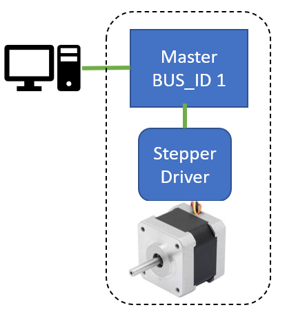
Each Arduino's firmware has a configuration for specifying the operating mode. There are four modes: SLAVE_SERIAL0, SLAVE_SERIAL1, MASTER_SERIAL0, and MASTER_FORWARDING. They are explained below, and only one of the modes can be active based on your configuration and hardware.MASTER_SERIAL0 This mode uses a single Arduino over USB with no additional Arduinos connected to the serial network. There is no serial network for this setting. This is for a single Arduino with one stepper.
Enable MASTER_SERIAL0 if all of these conditions are met...
- this is the only Arduino that will be connected to the PC (i.e., you only need one stepper motor)
- this Arduino is connected to the PC via the USB cable
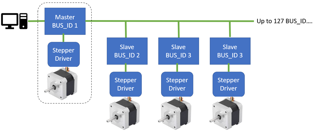
MASTER_FORWARDING This mode configures this Arduino as a forwarder for multiple Arduinos on the serial network. This master Arduino will be connected to the PC via the USB cable. All slave Arduinos will link to this Arduino's Serial1 port (TX1/RX1) with diodes for each Arduino.
*Disclaimer: the serial network may not work with all Arduino. You may also not mix 5v and 3.3v Arduino on the serial network.
Enable MASTER_FORWARDING if all of these conditions are met...
- this Arduino is the master with BUS_ID 1
- this Arduino has more than 1 Serial port (i.e., it has RX1/TX1 pins)
- there are other Arduinos connected to the RX1/TX1 of this master Arduino in a serial network
*Note: If you use FORWARDING mode and receive an error about Serial1 not being defined, then this Arduino does not qualify for this mode.
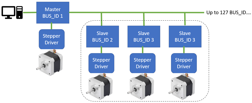
SLAVE_SERIAL0 This Arduino's RX0/TX0 pins are connected to a master Arduino's RX1/TX1 pins as part of the serial network.
Use SLAVE_SERIAL0 mode if all of these conditions are met...
- this Arduino is part of the serial network as a slave (it is not a master)
- this Arduino has onboard RX0/TX0 pins, and they're connected to the master Arduino's RX1/TX1 pins
- there is a diode on this Arduino's TX0 pin that is connected to the master Arduino's RX1 pin

SLAVE_SERIAL1 This Arduino's RX1/TX1 pins are connected to a master Arduino's RX1/TX1 pins as part of the serial network.
Use SLAVE_SERIAL1 mode if all of these conditions are met...
- this Arduino is part of the serial network as a slave (it is not a master)
- this Arduino has onboard RX1/TX1 pins, and they're connected to the master Arduino's RX1/TX1 pins
- there is a diode on this Arduino's TX1 pin that is connected to the master Arduino's RX1 pin
*Note: If you use SLAVE_SERIAL1 mode and receive an error about Serial1 not being defined, it means this Arduino does not meet the requirements for this mode.
Serial Network (optional)
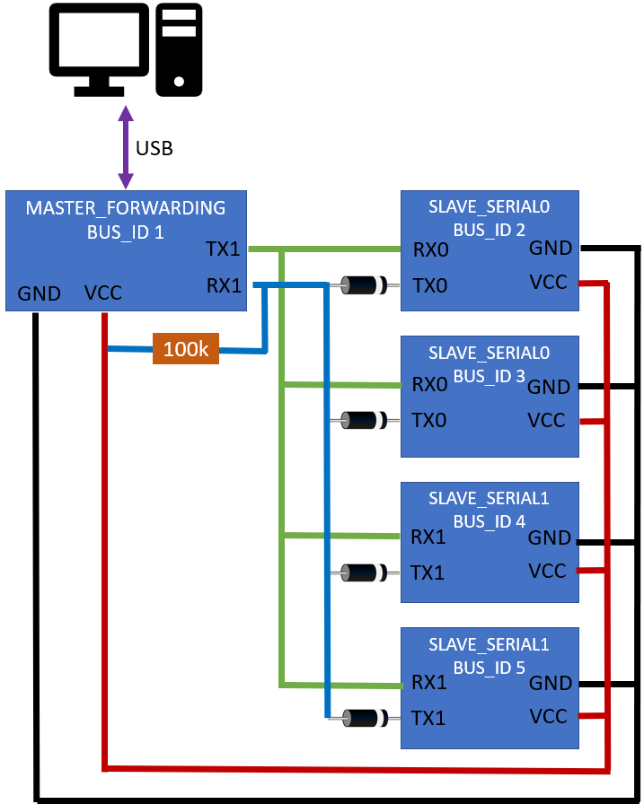
Optionally, you can connect multiple Arduinos in a serial network to share the same USB connection. This requires the first Arduino (the master) to have two serial ports. You can recognize if the first Arduino has two serial ports by the presence of the RX1 and TX1 pins.*Note: The firmware has documentation explaining various modes for which the Arduino can be configured.
This diagram demonstrates how multiple Arduinos can be connected to a Master Arduino with a diode. Ensure the diode's band is facing the correct direction. The 100k ohm resistor holds the RX1 high because the diodes prevent the slave TX lines from doing so.
Configuration
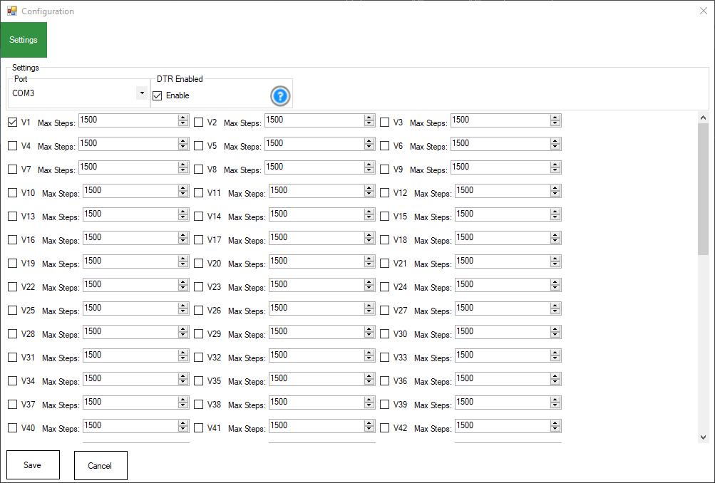
1) Port Select the COM port for the Arduino 1 wire serial network interface.
2) DTR Enabled Some Arduinos (e.g., Leonardo, Pro Micro) require this setting to be enabled for communication. If your Arduino is unresponsive when querying Ping or getting a servo position, this may need to be enabled. It is enabled by default.
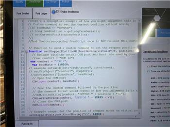
3) Virtual Port Selections Put a checkbox next to each Virtual Port you wish to bind to the stepper motors. For example, BUS_ID 1 is V1. And BUS_ID 5 is V5, etc. Any commands to move the Vx port will be sent to the respective stepper motor with the matching BUS_ID. Sending a Servo.setPosition(v2, 100) will move the stepper motor with BUS_ID 2 to position 100.
4) Max Steps Each virtual port has a Max Steps setting that determines how many steps a stepper motor will move when given a servo position from ARC.
The ARC Max servo Position setting (found in ARC Project Settings) defines the upper limit of servo positions used to control the stepper. By default, this value is 180, but it can be increased up to 2 billion.
The Max Steps setting defines how many total steps the stepper will move when a position at the ARC Max servo Position value is commanded. For example:
- If
Max servo Position = 180(default) - And
Max Steps = 1500
Then:
- Sending servo position 180 Stepper moves 1500 steps
- Sending servo position 90 Stepper moves 750 steps
- Sending servo position 1 Stepper moves 0 steps (minimum position)
Stepper Movement Formula
stepperPosition = Map(servoPosition, arcMinServoPositions, arcMaxServoPositions, 0, maxStepperPositions);
Where:
servoPositionis the position value sent to the stepper (1 to Max servo Position)arcMinServoPositionsis the minimum value (always 1 in ARC)arcMaxServoPositionsis the configured maximum servo value in ARC (default 180)maxStepperPositionsis the number of steps this stepper should take at the max position (i.e., the Max Steps setting)
The servo position you send is scaled between 0 and Max Steps, based on the configured Min (1) and Max servo Positions in ARC. This makes it possible to have consistent, precise control over stepper motors using ARC's standard servo interface.
Advanced servo Features
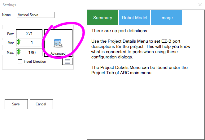
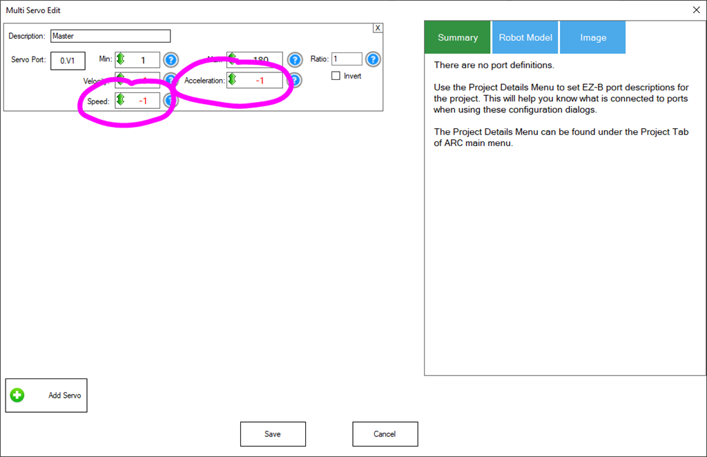
This supports the advanced options of servos for Speed and Acceleration settings. By configuring the acceleration option in ARC's advanced servo settings, the stepper motors will speed up and slow down between their source and destination positions.When editing a robot skill for the servo configuration, the Advanced button allows you to specify the speed and acceleration. You may also use the respective JavaScript, Python, and EZ-Script commands to determine the speed and acceleration programmatically.
A lower acceleration value will cause the stepper to accelerate slower as it begins to move. -1 means not changing by maintaining the current setting, and 0 means no acceleration.
Home Position
The HOME position is servo position 1 in ARC. By default, the position on power-on of all steppers and their respective Arduino's will be servo position 1. The ControlCommand can specify any position to become HOME (position 1). This robot skill has a ControlCommand for setting the HOME position to calibrate the stepper motor positions. Additionally, you can use an end-stop limit switch to calibrate the stepper into the home (position 1). A stepper motor knows its position by how many "steps" have been sent to move it in either direction. During the operation, the Stepper servo Arduino Firmware keeps track of the steps and, therefore, the relative position. However, because the position is arbitrary on power-on, you may need to calibrate it using an Endstop Limit Switch.Endstop Limit Switch
This robot skill supports an optional limit switch connected to the Arduino for calibrating the position of the stepper motor to become servo Position 1. When the switch is closed to GND, the stepper will automatically be configured to be in servo position 1 in ARC. When the end limit switch is shorted, this is similar to sending the SetAsHome ControlCommand to the Arduino for the specified virtual port. The Arduino firmware can be edited to include the option of auto-calibrating when power is applied. Otherwise, you can programmatically enable calibration with the control command.Place a limit switch on the lowest position of the lever connected to the stepper motor. If configured, this switch will be used as the limit switch. When calibrating, the stepper will move toward the lowest position until the limit switch is reached. Once the limit switch is reached, that will be position 1 in ARC until the power is cycled. There is no memory of the position between power cycles. The lowest position means the stepper begins rotating by decreasing from the current position.
Ensure the calibration rotates your stepper in the correct direction, which will be position 1 in ARC. If the stepper rotates in the wrong direction, you may need to specify the INVERT option in the firmware. The limit switch should always be at the lowest position for the stepper, which means position 1 in ARC.
Increase servo Resolution
ARC has a project-wide setting for increasing the servo resolution across all robot skills. Increasing this value will give the stepper a high resolution supported by your stepper motor.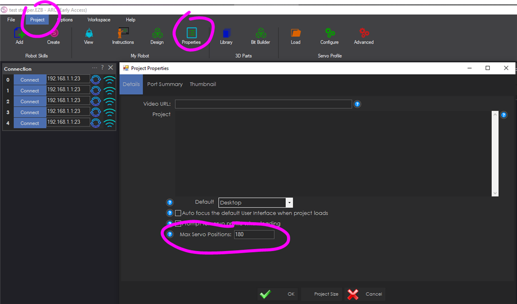
Test Bi-direction Communication
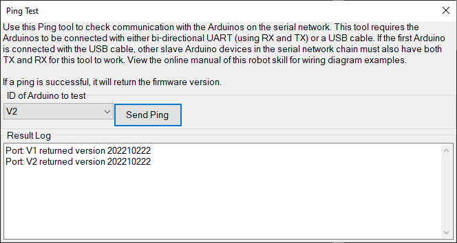
This allows the Arduino to report the current position of the stepper during movement using the script command GetPositionRealtime(). This command will retrieve the real-time position of the stepper from the respective Arduino. The Arduino's are responsible for moving the stepper, including acceleration and speed.The robot skill main screen has a Ping menu option to test bi-directional communication.
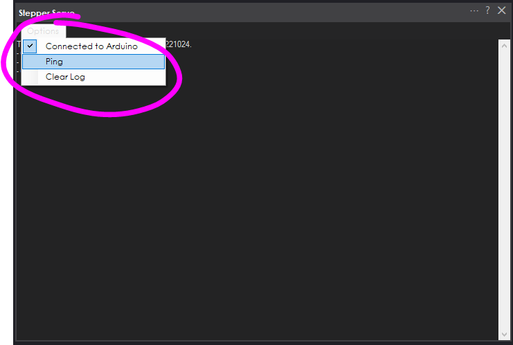
When the ping option is selected, a new window will open with options to ping the Arduinos and view their firmware version. Here, you can choose the port for each Arduino on the serial network to verify communication and the version number.
Control Commands
There are several ControlCommand() for interacting with the stepper servo robot skill.ControlCommand("Stepper Servo", "Calibrate", "ServoPort"); This ControlCommand takes the virtual servo port as the parameter. It will instruct the Arduino with the ARC Stepper servo firmware to move the stepper until the End Limit Switch is triggered. This command requires an end-limit switch; otherwise, the stepper will rotate indefinitely. Refer to the Limit Switch section in this manual to read more about a limit switch and how to configure it. The servo port is the virtual servo that matches the ID; for example, if the Arduino firmware is configured for ID1, this will be V1.
ControlCommand("Stepper Servo", "SetAsHome", "ServoPort"); The SetAsHome command will set the current position of the stepper as servo position 1. For example, if you move the servo into a position (i.e., 90) and then specify the SetAsHome control command, the current position will become the new servo position 1 for that virtual port. servo position 1 is as low as a servo can move, so when you send SetAsHome to the specified virtual port, it will now refer to the current position as 1. The servo port is the virtual servo that matches the ID; for example, if the Arduino firmware is configured for ID1, this will be V1.
Arduino Firmware
The Arduino code must be downloaded from here and programmed onto each Arduino. The recommended Arduino for this usage would be small and affordable, such as a Pro Micro, Micro, Nano, or ATTiny. These are all very low-cost devices that are small and do not take up much space.Download Arduino Firmware from here: Stepper_Servo (Version 20230223).zip (Updated Feb 23, 2023)
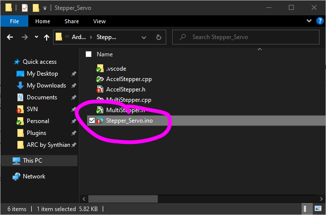
Uncompress the firmware to a folder and open the INO file with the Arduino editor
Configure the BUS_ID on the one-wire serial network in the Arduino editor for this instance. It can be a number between 1 and 127. This number will correspond with the respective Virtual servo Port in ARC. Each Arduino/Stepper will have a unique ID. Remember, the ID corresponds to ARC virtual servo numbers. So BUS_ID 2 is ARC's servo port V2.

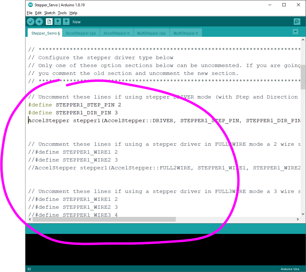
In the Arduino editor, configure the type of stepper driver that you will have connected to the Arduino. There are multiple types of stepper drivers to be supported, including two-wire, three-wire, four-wire, etc. Uncomment the section of the kind you will use with this Arduino. Only one area can be uncommented at a time, so comment out another section if editing a previous configuration.
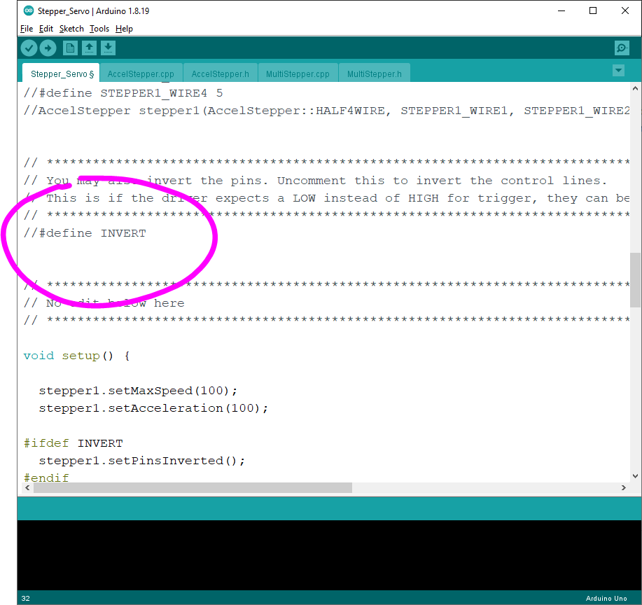
In the Arduino editor, you can configure control line wires from the Arduino to the Stepper Driver if they need to be inverted. This is only if the stepper driver requires an inverted GPIO so that HIGH becomes LOW and vice versa.
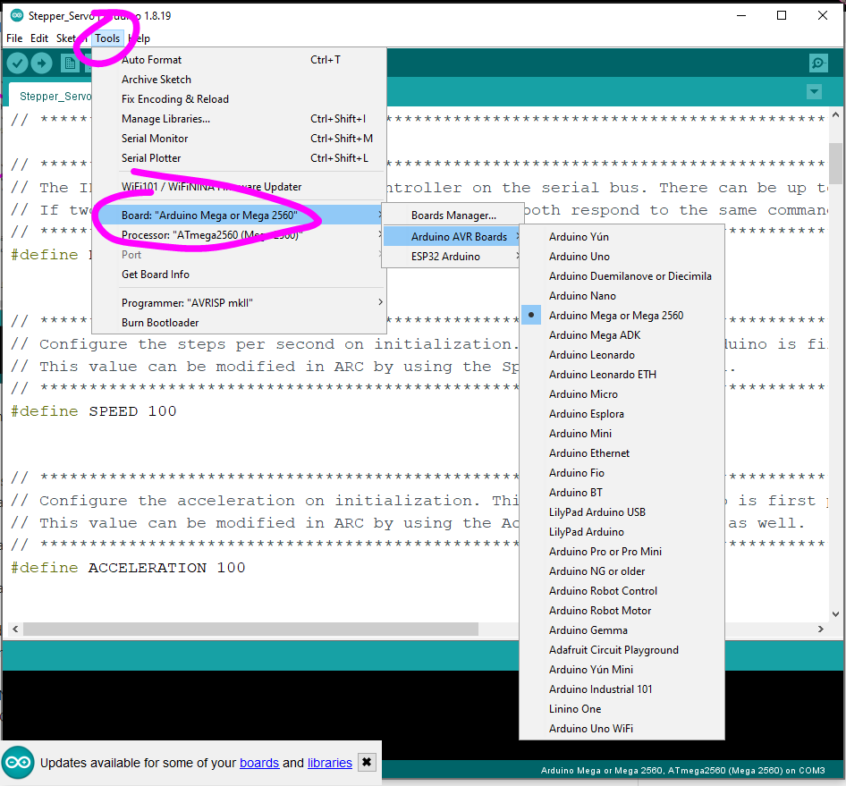
Ensure you have selected the correct Arduino Board that you are using
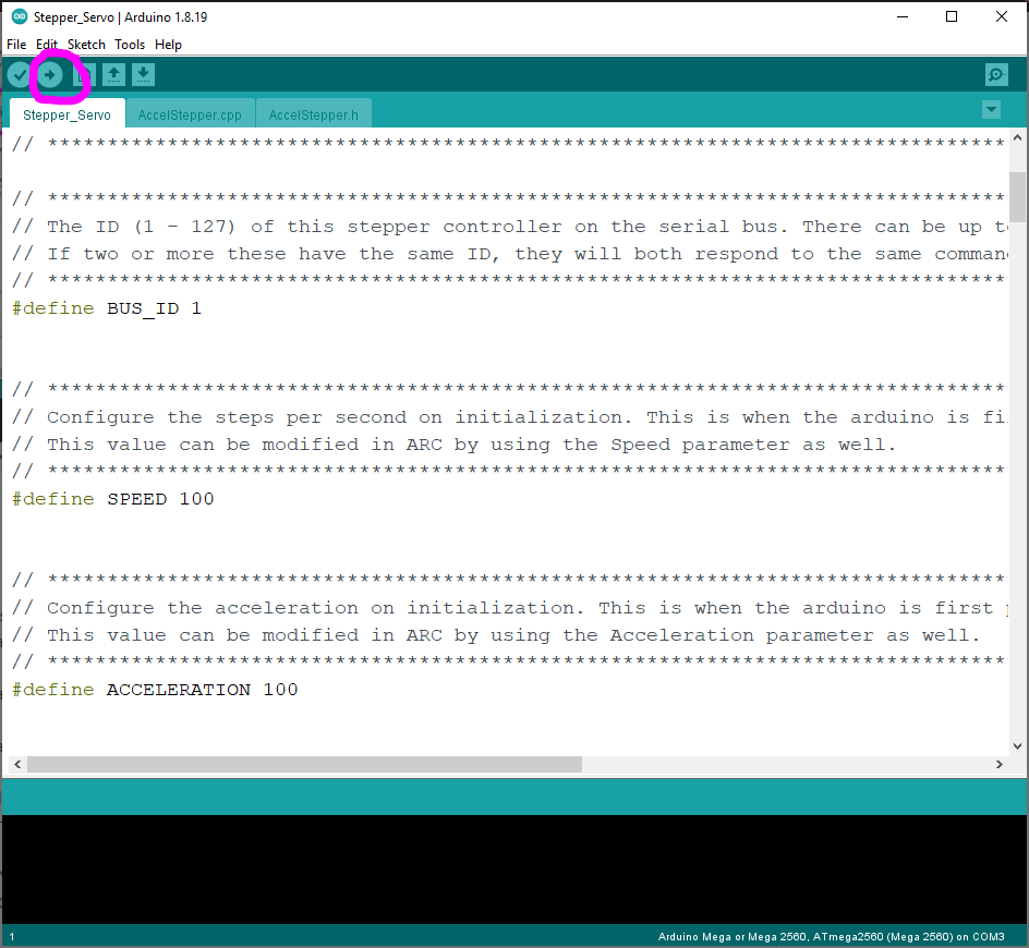
Program the Arduino with the edited code.
Troubleshooting
Ensure you have the latest Arduino firmware installed on your Arduino(s)
Ensure you have the latest Stepper servo robot skill installed in ARC
Ensure you have the latest ARC installed (Early Access edition is recommended)
The stepper driver needs to be connected to the Arduino I/O pins. Ensure the pins are connected and specified in the Arduino firmware. Ensure you uncommented the correct stepper driver type in the Arduino firmware before uploading it to the Arduino.
A common GND is necessary across all electronic devices. Ensure the stepper motor driver, stepper motor, Arduino, and PC have a common ground. The Arduino will be grounded to the PC if connected via a USB cable.
The configured BUS_ID on the Arduino must match the selected checkboxes in the Robot Skill's configuration screen
Remember, the BUS_ID in the firmware will match ARC's Virtual servo (Vx) ports. So BUS_ID 1 will match V1 in ARC. BUS_ID 2 will match V2 in ARC, and so on...
Related Questions
Different Pages In Blockly
Home Stepper Motor

Upgrade to ARC Pro
Your robot can be more than a simple automated machine with the power of ARC Pro!
Genius work here.
Thanks for the new control,
I will try it out
your Arduino firmware works, connects on my com port 11
when I uploaded new Accelstepper ino to Arduino, then try to connect on ARC, so far, com11 can't connect
My Arduino, I use 57600 to run your Arduino firmware software
I tried all the baud rates
Can't figure it out what can be the reason
any Ideas?
What do you mean by that?
I believe it is the baud rate
#define _BAUD_RATE 57600
When I go to the COMUBS connection
That menu is not from this robot skill. Read the instructions above.
Updated to v3
new firmware
fix for acceleration
tested on arduino without stepper motor. The steps for positioning is most likely WAY off and needs to be adjusted. I'll do that next week when i get a stepper motor to test with.
Updated to v4
Ok, sounds good
so far I read that, I added Stepper Servo, says connected to com11