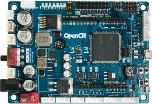
Opencr by Robotis
Beginners tip: ARC talks to microcontrollers over a USB “COM port” using a speed called baud rate. This firmware uses a very fast baud rate (921,600), so make sure ARC is set to match.
Install the Firmware Source Code (Arduino IDE)
You will use the Arduino IDE to open, compile, and upload (flash) the firmware to the OpenCR board. “Firmware source code” means the human-readable code you compile into the program that runs on the board.
-
Download and install the Arduino IDE.
If you already have it installed, open it once to ensure it starts correctly.
-
In Arduino IDE, go to File → Preferences.
In the Additional Boards Manager URLs box, paste this link:
https://raw.githubusercontent.com/ROBOTIS-GIT/OpenCR/master/arduino/opencr_release/package_opencr_index.jsonThis tells Arduino IDE where to download the OpenCR “board package” (drivers, definitions, examples, and tools for this controller). -
Install the OpenCR board package:
- Go to Tools → Board → Boards Manager
- Search for
OpenCR - Find OpenCR by ROBOTIS and click Install
When it finishes, you should see it marked as INSTALLED. -
Select the OpenCR board in Arduino IDE:
- Go to Tools → Board
- Select OpenCR Board (or a similarly named OpenCR option)
Selecting the correct board ensures the code compiles for the OpenCR’s ARM CPU and uploads properly. -
Download the ARC-compatible firmware source code:
- Download DJ's OpenCR v1 Firmware Sourcecode (Jan 9, 2021)
After downloading, unzip the file to a folder you can easily find (for example, your Desktop). -
Follow the step-by-step guide to compile and upload (flash) the firmware:
Uploading firmware replaces the program on the board. If upload fails, double-check the selected COM port under Tools → Port.
Connectivity (ARC Settings)
Many Arduino-style devices use 9600 baud by default, but the OpenCR firmware used here is configured for a much faster connection: 921,600 baud.
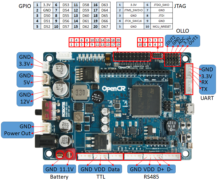
Ports (How ARC Maps to OpenCR Pins)
ARC uses familiar port naming (such as D0–D13 for digital and A0–A* for analog).
OpenCR labels and capabilities can differ, so it’s helpful to reference the official pin mapping.
Technical pinout and examples from ROBOTIS: https://emanual.robotis.com/docs/en/parts/controller/opencr10/#examples
Beginner-friendly notes:
-
Ax ports: These can be used as Analog Inputs (reading sensor values like potentiometers, distance sensors, etc.) or as Digital I/O depending on how you use them.
In other words, an
A*pin can often behave like aD*pin. -
UART ports: The OpenCR has hardware serial ports. In this firmware mapping:
- UART 0, 1, 2 map to UART 1, 2, 3 respectively in ARC
- If you are unsure which pin to use for a device in ARC, consult the ROBOTIS mapping page above to confirm the correct OpenCR header/pin and its supported modes.
PWM Pins (For Servos, Motor Speed, LED Dimming)
PWM stands for Pulse Width Modulation. ARC uses PWM for things like:
- Controlling servo positions
- Controlling DC motor speed (with a compatible motor driver)
- Dimming LED brightness
3, 5, 6, 9, 10, 11.
ARC EZ-Script Example (Blink the Onboard LED)
The OpenCR has an onboard LED connected to Digital 13 (D13 in ARC).
This script turns the LED on and off every 500 milliseconds (half a second) in a loop.
:loop

Set(d13, true)

sleep(500)

Set(d13, false)

sleep(500)

goto(loop)