

Read TTL digital input from an ARC I/O port; real-time red/green status for low (0V) or high (+3.3/5V), selectable board/port and read interval.
How to add the Read Digital robot skill
- Load the most recent release of ARC (Get ARC).
- Press the Project tab from the top menu bar in ARC.
- Press Add Robot Skill from the button ribbon bar in ARC.
- Choose the Digital category tab.
- Press the Read Digital icon to add the robot skill to your project.
Don't have a robot yet?
Follow the Getting Started Guide to build a robot and use the Read Digital robot skill.
How to use the Read Digital robot skill
The Read Digital robot skill shows the current ON/OFF state of a digital input pin on your I/O Controller.
It is a graphical version of the ARC script command ReadDigital().
Digital inputs use TTL logic, which means the controller reports:
- LOW = about 0V (often considered “OFF”)
- HIGH = about +3.3V or +5V (depends on your I/O Controller; often considered “ON”)
ReadDigital() inside an ARC script.
Main Window
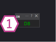
1. Digital Status Indicator
This indicator changes color based on the voltage detected on the selected digital input port:
- Black — No I/O Controller is connected (or ARC is not connected to the board yet).
- Red — The port is reading LOW (near 0V).
- Green — The port is reading HIGH (near +3.3V or +5V, depending on the controller).
Settings
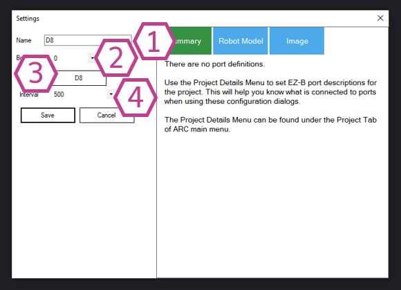
- Smaller number = faster updates, more frequent polling.
- Larger number = slower updates, less CPU/communication usage.
If you’re unsure, start with a moderate interval (for example, 100–250 ms) and adjust as needed.
How to Use Read Digital (Step-by-Step)
- Add the skill to your project: In ARC, go to Project → Add Skill → Digital → Read Digital.
- Connect to your I/O Controller: Make sure ARC is connected to your board. Before connecting, the indicator will remain black.
-
Open the skill settings and select:
- Board (the controller you are using)
- Port (the digital input where your sensor/switch is wired)
- Interval (how often you want updates)
- Watch the indicator on the main window: Toggle your switch or trigger your sensor and confirm the indicator changes between red (LOW) and green (HIGH).
When Should I Use This Skill?
Good for
- Checking if your wiring is correct
- Testing a sensor before writing scripts
- Learning what HIGH and LOW look like in real time
- Quick troubleshooting (is the port changing?)
Not a replacement for
- Using
ReadDigital()in scripts for robot logic - Event-driven behaviors (where scripts react to input changes)
- Projects where minimizing polling/overhead is important
Requirements
- An I/O Controller that supports digital input ports.
- A device that provides a digital output (LOW/HIGH), or a switch wired to produce LOW/HIGH.
Related Tutorials
Related Hack Events

Related Questions
Ezbpi Server - Access To The Pi Gpios
More DIO Ports Required

Upgrade to ARC Pro
Stay at the forefront of robot programming innovation with ARC Pro, ensuring your robot is always equipped with the latest advancements.
Can this actually detect a high value 3.3v or 5v and a low value 0v on a typical output or does it have to be the ADC? I noticed you are using D8. Could you explain how it's doing this? Does it need a separate device to interpret it, could give an example of the device?
Hi @Automation Man
I can confirm that DigitalRead does indeed detect a high signal (3.3V for EZ-Bv4 which is also 5V tolerant) and low signal.
I have read that the threshold for a high signal has to be above 1.88V and for a low voltage it has to be under 1.23V for STM32 chips.
The skills uses the Digital I/O pins in the "I" (input configuration) and reads the voltage on the D8 (or otherwise setup) Digital pin to see if it's either under 1.23V (low - red) or above 1.88V (high - green).