

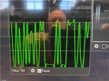
ADC VU meter displaying 0-3.3/5V as a 0-255 linear meter; configurable board/port, sampling interval and color; pausable real-time readings.
How to add the ADC Meter robot skill
- Load the most recent release of ARC (Get ARC).
- Press the Project tab from the top menu bar in ARC.
- Press Add Robot Skill from the button ribbon bar in ARC.
- Choose the ADC category tab.
- Press the ADC Meter icon to add the robot skill to your project.
Don't have a robot yet?
Follow the Getting Started Guide to build a robot and use the ADC Meter robot skill.
How to use the ADC Meter robot skill
The ADC Meter robot skill displays an EZ-B analog input as a live VU-style meter. This is ideal for quickly seeing the level of an analog sensor without needing a scrolling graph.
ADC stands for Analog-to-Digital Converter. An ADC port reads a changing voltage from a sensor and converts it into a number ARC can use. The EZ-B ADC measurement range is from 0V up to the controller’s TTL High voltage (typically 3.3V or 5V, depending on your I/O controller configuration).
ARC represents the measured voltage as a linear value from 0 to 255:
- 0 = 0V
- 255 = TTL High (3.3V or 5V)
- Values between are proportional to the voltage level.
Main Window
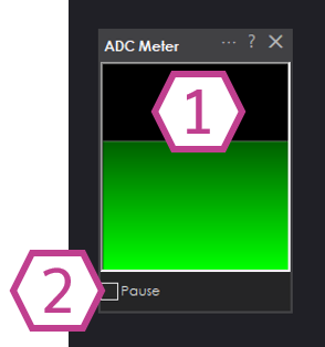
1. Meter Display
Displays the current ADC value as a vertical meter (VU meter style). The meter height increases as the ADC value approaches 255.
This makes it easy to see level changes at a glance.
2. Pause Checkbox
When checked, ADC sampling is paused and the meter will stop updating. Uncheck to resume live readings.
Settings
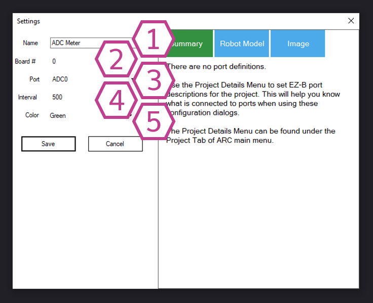
1. Title Field
The name of this skill as it appears in your ARC project.
Note: Changing the title will also change the identifier used by controlCommand() when sending commands to this skill.
2. Board Drop-down
Select the EZ-B connection index (board number) that contains the ADC port you want to read.
This setting is important when you have more than one EZ-B connected in the same ARC project.
3. Port Drop-down
Select the ADC (analog) port number that your sensor is connected to. Only analog-capable ports will return a valid ADC value.
4. Interval Drop-down
Select the time (in milliseconds) between ADC samples. Smaller intervals update the meter more frequently, but can increase CPU usage and controller traffic.
Larger intervals update less frequently and are often fine for slow-changing sensors.
5. Color Drop-down
Select the color used for the meter display. This can help with visibility or matching your project theme.
How to Use ADC Meter
- Add the skill to your ARC project: Project → Add Skill → ADC → ADC Meter.
- Open Settings and select the correct Board and ADC Port where your analog device is connected.
- View the meter level in the Main Window. Use Pause to freeze the reading for inspection.
ADC ports measure voltage. Ensure your sensor output stays within the safe range of 0V to TTL High (3.3V or 5V). Exceeding this range can cause inaccurate readings and may damage the controller.
Video
Requirements
Related Tutorials
Flex Sensor With An ADC Port Tutorial
Using ADC (Analog To Digital) Ports, Commands And Controls.
Related Questions

Upgrade to ARC Pro
Take control of your robot's destiny by subscribing to Synthiam ARC Pro, and watch it evolve into a versatile and responsive machine.