
Inverse kinematics for Robotis OpenManipulatorX: compute joint angles and MoveTo 3D (cm) positions, supports camera-to-CM mapping for pick-and-place.
 Hardware Info
How to add the Robotis Openmanipulatorx robot skill
- Load the most recent release of ARC (Get ARC).
- Press the Project tab from the top menu bar in ARC.
- Press Add Robot Skill from the button ribbon bar in ARC.
- Choose the Servo category tab.
- Press the Robotis Openmanipulatorx icon to add the robot skill to your project.
Don't have a robot yet?
Follow the Getting Started Guide to build a robot and use the Robotis Openmanipulatorx robot skill.
How to use the Robotis Openmanipulatorx robot skill
Inverse kinematics calculates the joint angles to position the Robotis Open ManipulatorX effector to a specific desired location in 3d cartesian space.
Inverse Kinematics
Inverse kinematics is a computational process used in robotics to determine the joint configurations necessary to position and orient the end-effector (usually a robot arm's hand or tool) at a specific target location and orientation in three-dimensional space. It involves solving equations that map the desired end-effector pose to the joint angles, allowing the robot to perform precise and coordinated movements to reach its intended target. Inverse kinematics is crucial for tasks like picking and placing objects, drawing paths, or interacting with the environment, as it enables robots to plan and execute motions with accuracy.Cartesian Space
In 3D Cartesian space, also known as three-dimensional space, positions are represented using three coordinates: x, y, and z, typically measured in centimeters (CM). This space allows us to describe the location of a point or object in a three-dimensional environment. The x-coordinate specifies the position along the horizontal axis, the y-coordinate represents the vertical position, and the z-coordinate indicates the depth or position along the third dimension, forming a 3D reference system that is essential for various applications, including computer graphics, engineering, and robotics.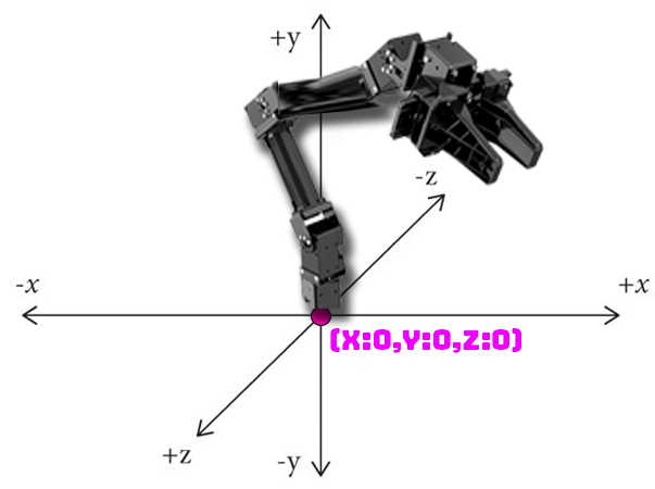
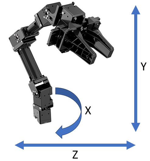
The center at the robot's base is position 0, 0, 0. Modifying the X-axis swivels the arm left or right. Modifying the Y axis raises/lowers the gripper. Modifying the Z axis will extend/retract the robot arm gripper outward or inward.
Use Cases
Imagine you have a robot arm with several joints, and you want it to grab a cup from a table. Inverse kinematics helps determine how to bend and move each robot arm joint to make the hand land on the cup exactly where you want it, even if the cup's location changes. It's like solving a puzzle to figure out the right angles for the robot's joints so it can reach and grasp objects in a controlled and accurate way, making it a fundamental skill for tasks like picking and placing objects, drawing, or interacting with the world.Robotis OpenManipulatorX
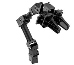
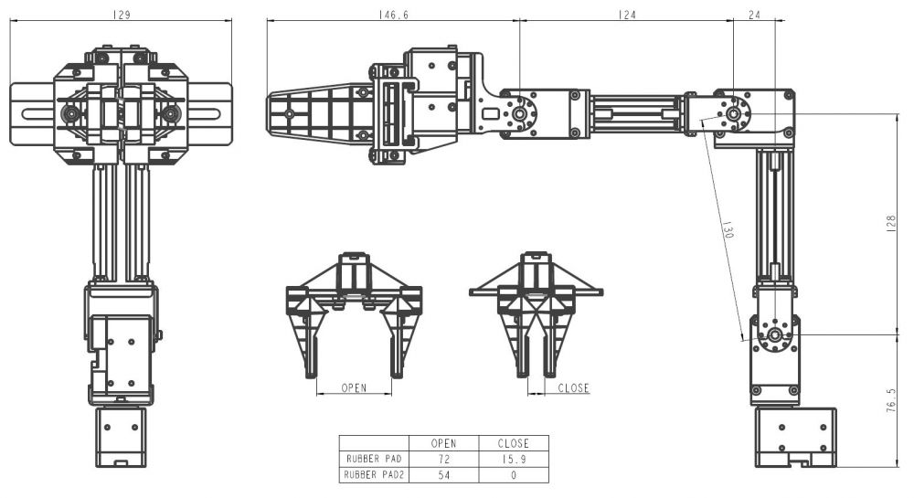
The Robotis OpenManipulatorX is a robotic arm developed by Robotis, responsible for the Dynamixel servo series. It is designed for educational and research purposes and is often used as a platform for teaching robotics and learning about robot manipulation.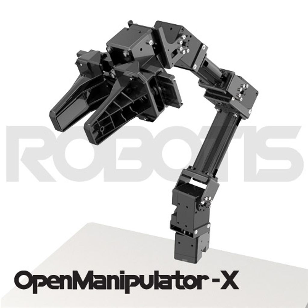
End Effector
In robotics and automation, an end effector is a device or tool at the tip of a robotic arm or manipulator. It serves as the "hand" of the robot, and its primary function is to interact with the environment, perform specific tasks, and manipulate objects. End effectors are critical components in a wide range of robotic applications, and their design can vary significantly based on the intended task.Main Window
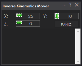
X Value With inverse kinematics, modifying this value moves the end effector to the specific X (left/right) offset from 0 (robot base) in centimeters. With forward kinematics, this value will display the current calculated X offset.
Y Value With inverse kinematics, modifying this moves the end effector to the specific Y (up/down) offset from 0 (ground) in centimeters. With forward kinematics, this value will display the current calculated Y offset.
Z Value With inverse kinematics, modifying this moves the end effector to the specific Z (forward/backward) offset from 0 (center) in centimeters. With forward kinematics, this value will display the current calculated Z offset.
*Note: The X/Y/Z values will be updated automatically to the current cartesian coordinate using forward kinematics if the servos are moved from another robot skill or through code.
Panic Releases the servos on the arm if it is jammed or stuck due to specifying an incorrect location that collides with something.
Config Window
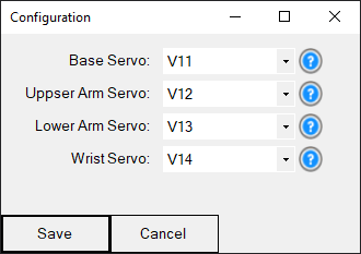
Base Servo (first joint) This is the servo at the robot's base, which swivels the arm back and forth along the X-axis.
Upper Arm Servo (second joint) This is the servo at the upper arm closest to the base servo that lifts the upper arm upward and downward.
Lower Arm Servo (third joint) This is the servo at the lower arm between the upper arm and wrist that lifts the middle arm upward and downward.
Wrist Servo (fourth joint) This is the servo at the wrist closest to the gripper servo that lifts the gripper (end effector) upward and downward.
Control Commands
The robot arm can be instructed to move into a specific cartesian coordinate with the MoveTo control command. This is a JavaScript example of moving the servo into the X position of 0cm, Y position of 10cm, and Z position of 15cm. The available ControlCommand can be viewed using the Cheat Sheet or right-click in any code editor.
ControlCommand("Inverse Kinematics Mover", "MoveTo", 0, 10, 15);
Requirements
This robot skill requires the Dynamixel robot skill to be added to the project. The robot servos must be set for the xl430_w250 in Position mode. The Max Position value must be set for 4095 to compensate for the resolution of the xl430 servos.
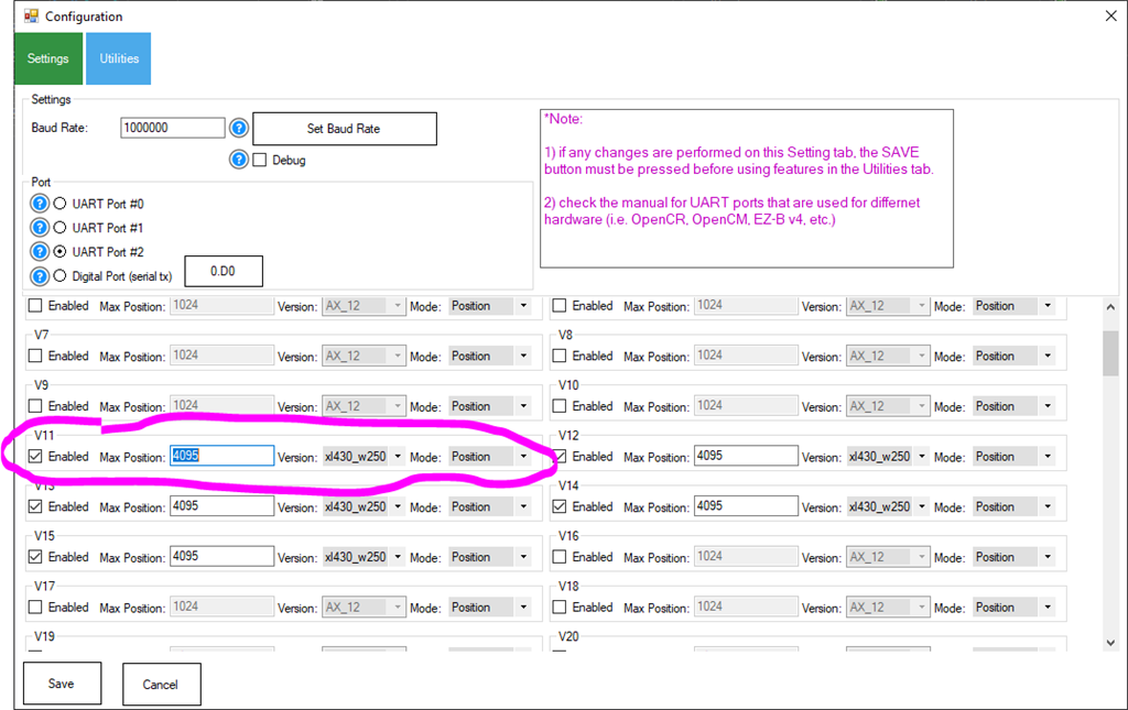
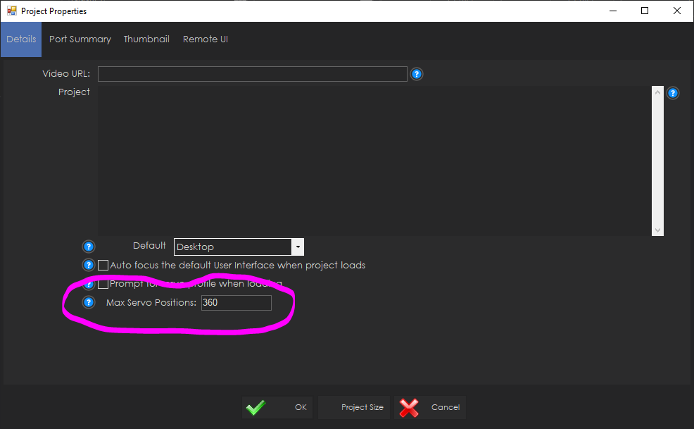
The ARC global Max servo Position value must be set to 360 to compensate for the rotation available to the xl430 servos. This can be done in the Project -> Settings menu in ARC.
Camera Pickup Object
You may have a camera above a spot, looking down where a robot arm can reach. The Camera Device robot skill is smart and can recognize objects, like a special marker called a glyph. When the camera sees this object, it notes its position as X and Y coordinates in pixels in the global variable storage.We want the robot arm to reach and grab the object. Now, this robot skill works coordinates in centimeters (CM), and the camera uses pixels. You can use a function called JavaScript Utility.map() to convert from pixels to CM. But remember, the exact conversion depends on how your robot arm is set up and how far the camera is from the area. So, you'll need to fine-tune those CM coordinates based on your specific setup.
The code below is a script for controlling a robot arm with a gripper and a camera. Here's a breakdown of what it does:
Servo.setPosition(v15, 260);- This line opens the gripper by setting the servo to open the gripper.sleep(1000);- This line pauses the script for 1000 milliseconds (or 1 second) to allow the gripper to fully open.The next block of code calculates the X and Z coordinates for the robot arm to move to. It does this by mapping the X and Y coordinates of the detected object in the camera view (pixels) to the robot arm's coordinate system (CM).
ControlCommand("Inverse Kinematics Mover", "MoveTo", x, 1, z);- This line sends a command to the robot arm to move to the calculated X and Z coordinates. The Y coordinate is set to 1, which represents a fixed height 1cm from the table/surface.sleep(2000);- This line pauses the script for 2000 milliseconds (or 2 seconds) to allow the robot arm to move to the target position.Servo.setPosition(v15, 190);- This line closes the gripper by setting the servo controlling the gripper to a specific position. The value to close the gripper should be customized for your object, as to not put strain on the servo.
*Note: The specific values used for the servo positions and the mapping of the camera coordinates to the robot arm coordinates might need to be adjusted for your specific robot arm and camera setup.
This could be pasted in the Camera Device's "Tracking Start" script for JavaScript...
// Open gripper
Servo.setPosition(v15, 260);

// Pause while the gripper opens
sleep(1000);

// Get the X axis (left/right) based on the X axis of the detected object in the camera
  var x = Utility.map(
getVar("$CameraObjectX"),
0,
320,
-20,
20);

  // Get the Z axis (back/forth) based on the size of the detected object in the camera
  var z = Utility.map(
getVar("$CameraObjectY"),
0,
240,
30,
15);

// Move the arm to the location of the detected object
  ControlCommand("Inverse Kinematics Mover", "MoveTo", x, 1, z);

// Pause while the robot moves to the position
sleep(2000);

// Close gripper (fine-tune for your object size)
Servo.setPosition(v15, 190);
Camera Object Tracking Example
Imagine making a computer program that controls a robot's hand (the part that grabs things) based on what a camera sees. In this case, let's pretend the camera has a picture with 320 pixels across and 240 pixels up and down. We'll use this picture to make the robot hand move up and down (from -20 to 20 centimeters) and left to right (5 to 35 centimeters). We can also determine how close an object is to the camera by looking at its size and mapping it to a distance from 20 to 30 centimeters.The provided code is a continuous loop that uses a camera to detect an object and then moves the robot arm based on the object's position and size. The Utility.map function converts the object's position and size from the camera's coordinate system to the robot arm's coordinate system.
Here's a breakdown of what the code does:
The
while (true)loop causes the code to run indefinitely. This is common in robotics and real-time systems where you want to monitor sensors and adjust the system's behavior accordingly continuously.The
getVarfunction is used to get the current position and size of the detected object from the camera in the global variable storage. The$CameraObjectX,$CameraObjectY, and$CameraObjectWidthvariables represent the object's horizontal position, vertical position, and size.The
Utility.mapfunction converts these values from the camera's coordinate system to the robot arm's coordinate system. For example, thexvalue is calculated based on the object's size, with larger objects resulting in a largerxvalue. This moves the robot arm closer to larger objects and further from smaller objects.The
ControlCommandfunction is then used to move the robot arm to the calculated position. The"Inverse Kinematics Mover"argument to this robot skill, and the"MoveTo"argument is the command to move to a specific position.The
x,y, andzvalues calculated earlier is passed as arguments to theControlCommandfunction. These represent the robot arm's desired position in its coordinate system (units are CM)
This code would be used for a camera to track an object and a robot arm to follow the object or maintain a certain position relative to it. This code can be placed in the Camera Device's "Tracking Start" script...
while (true) {

  // Get the X axis (spin) based on the X axis of the detected object in the camera
  var x = Utility.map(
            getVar("$CameraObjectX"),
            0,
            320,
            -20,
            20);

  // Get the Y axis (up/down) based on the Y axis of the detected object in the camera
  var y = Utility.map(
            getVar("$CameraObjectY"),
            0,
            240,
            35,
            5);

  // Get the Z axis (back/forth) based on the size of the detected object in the camera
  var z = Utility.map(
            getVar("$CameraObjectWidth"),
            40,
            100,
            20,
            30);

  ControlCommand("Inverse Kinematics Mover", "MoveTo", x, y, z);
}

@athena give me a summary of this robot skill and what it can be used for
The Inverse Kinematics robot skill is a computational process used in robotics to determine the joint configurations necessary to position and orient the end-effector (usually a robot arm's hand or tool) at a target location and orientation in three-dimensional space. This is done by solving equations that map the desired end-effector pose to the joint angles.
This skill is crucial for tasks like picking and placing objects, drawing paths, or interacting with the environment, as it enables robots to plan and execute motions with accuracy. It's particularly useful for a robot arm with several joints, like the Robotis OpenManipulatorX, as it helps determine how to bend and move each robot arm joint to make the hand land on an object exactly where you want it.
The robot arm can be instructed to move into a cartesian coordinate with the MoveTo control command. This robot skill requires the Dynamixel robot skill to be added to the project. The robot servos must be set for the xl430_w250 in Position mode. The Max Position value must be set for 4095 to compensate for the resolution of the xl430 servos. The ARC global Max servo Position value must be set to 360 to compensate for the rotation available to the xl430 servos. This can be done in the Project -> Settings menu in ARC.
This is great. I made my arm using LEWANSOUL LX16A instead fo Dinamixel servos, is it possible to adapt this to be used with those servos? Thanks in advance.
Not this robot skill as it's made specifically for the robotis openmanipulatorX. However, this is the initial product created with synthiam's new inverse and forward kinematics system. We're working on a robot skill that allows customizing your own arm dimensions for the kinematics system to work with your custom arm.
Excellent news! Thanks
Version 7 has been updated to swap X and Z axis because they were reversed. X should be horizontal and Z should be depth.