LIDAR

The LIDAR reference design simplifies the communication from the LIDAR and allows it easily interface to ARC. ARC then gives a visual representation of the data and starts mapping the area. We want to share these files with you so you can create your own!

Features


  • I2C breakout
  • EZ-B Camera breakout
  • LIDAR communication breakout
  • SWD programming header
  • 5V tolerant I/O pins
  • Mounting points for LIDAR unit
  • 5V energy efficient switching power supply
  • ARC skill available
  • Reverse polarity protection
  • Bicolor Blue/red indicator LED
  • Voltage requirement: 5-16VDC (7.4V Typical)
  • Dimensions: 149.4(W) x 95.3(L) x 39.6(H) (mm)
  • Weight: 166g


  • Major Components


  • STM32F401RBT6 ARM microcontroller (custom firmware provided)
  • RT8299GSP Switching power supply
  • HLS-LFCD2 LIDAR unit


  • Manufacturing Notes


  • Supplier: programs custom firmware into the STM32F401RBT6 at their facility before sending to manufacturer
  • Supplier: provides LIDAR unit
  • Manufacturer: Single side placement and soldering of SMT components
  • Manufacturer: Single Side soldering of THT components
  • Manufacturer: Assembles PCB and LIDAR unit together


  • Resources


    Documentation: Schematic PDF, Datasheet PDF, BOM

    Hardware: Altium PCB design File, Altium SCH Design File

    Altium Libraries are also available here
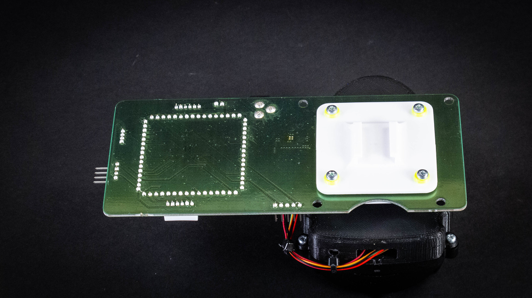
    Photos


    ARC Skill


    The ARC Skill for this reference design is very easy to use. With a few button clicks you can start mapping your robot's environment! 

    Link: https://synthiam.com/Software/Manual/EZ-LIDAR-SLAM-15944