

Control Roomba/Create via ARC: drive, stream sensors, read encoders, configure COM/HW UART, and send pose to NMS for mapping/navigation.
 Hardware Info
 Source Code
How to add the Irobot Roomba Movement Panel robot skill
- Load the most recent release of ARC (Get ARC).
- Press the Project tab from the top menu bar in ARC.
- Press Add Robot Skill from the button ribbon bar in ARC.
- Choose the Movement Panels category tab.
- Press the Irobot Roomba Movement Panel icon to add the robot skill to your project.
Don't have a robot yet?
Follow the Getting Started Guide to build a robot and use the Irobot Roomba Movement Panel robot skill.
How to use the Irobot Roomba Movement Panel robot skill
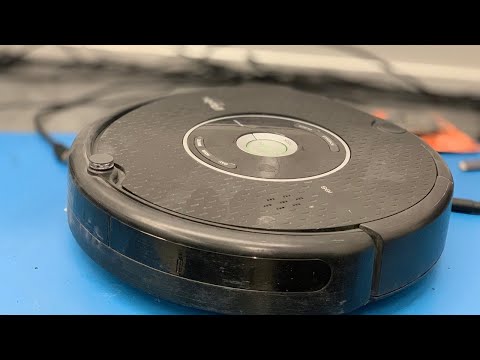
Control the iRobot Roomba and read sensor data. This skill currently works with the 500 and 600 series robots and iRobot create. The baud rate and connection type will need to be configured in the settings menu.
This robot skill can connect to an iRobot by using either a USB adapter or a microcontroller acting as an EZB (Arduino, etc.). The connection type in the config menu will specify the way this skill communicates with the iRobot. Continue reading below...
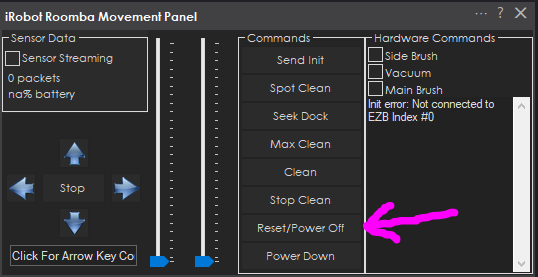
Main Window
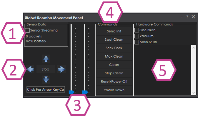
Enable sensor streaming and statistics of received sensor data. This requires a bi-directional connection. See below for different connection types and reading sensor data.
Movement directions to drive the robot, and a box to place the mouse cursor which enables using the keyboard arrow keys.
The speed for the left and right wheels, which defaults to 0.
Commands for initializing the SCI connection, enabling cleaning, stop cleaning, or powering off the robot
Status and log data for successful initialization and errors.
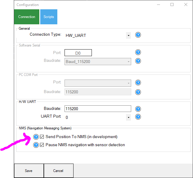
Config Window
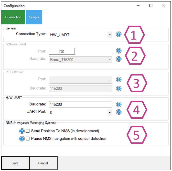
Connection type. Changing this setting will enable the selected connection type configuration below (Software serial, PC COM port, H/W UART). There is more information below in this manual on connection types.
Software Serial connection type. This type should only be used if there are no other supported options. This uses software serial on the EZB to emulate a transmitted serial signal. This is not 100% reliable and therefore should only be used if there are no other options. This is a one-way transmission, so sensor data cannot be read.
PC COM Port connection type. Uses a PC COM/Serial port that is usually a USB<->TTL convertor or an official iRobot Roomba USB cable (See details below). This is a bi-directional transmission, so sensor data can be read.
H/W UART on the EZB. Selecting this will use the HW UART if supported. This allows sensor data to be read because it is bi-directional.
NMS (Navigation Messaging System).
Enabling the first option in this group will send the iRobot Roomba's current coordinates to the NMS as a Level #3 Group #2 positioning/pose sensor. There is more information about this further in this manual.
The second option in this group will Pause NMS navigation if any of the iRobot Roomba sensors are triggered. The sensors covered are: cliff, bumper, virtual wall, and wheel drop
Baud Rates
Different models (i.e. create vs Roomba) use different baud rates. Find your Roomba's version and check it's SCI (Serial Command Interface) or OI (Open Interface) manual to see what baud rate it uses. We believe the Roomba uses baud rate 115200, and the create uses 57600. But, don't hold us to that . We do notice that older Roomba's use 57600 baud - ensure you have selected the correct baud rate in the config settings. 500+ series Roombas use 115,200 baud. If you are unsure, try each baud rate.
Demo Video Here's a video of the nice proportional steering that this control provides the iRobot Roomba. This video has the Roomba set to follow Kate's orange socks.
Like all movement panels, only one can exist. In this case, this Movement Panel will connect to a Roomba by its SCI interface. This control allows for a variety of speeds also, so you can use the analog joystick to control speeds. Or use the speed control in the camera to track objects with nice smooth trajectories.
ARC allows multiple physical robot controllers to be connected at once. The Movement Controls only operate on the first board (Board 0) or PC serial port.
Reading Sensor Data You can read sensor data if the PC COM or HW UART ports are used for the connection. This requires the TX and RX wires to be connected to the Roomba's SCI port. The data from the sensors and internal values are set as global variables. You can access everything from battery voltage to wheel encoder counts.
SCI Connection Types The connection types that can be used to connect the Roomba to ARC are:
- Software Serial (read-only)
- HW UART (read/write bi-directional two-way)
- USB COM TTL (read/write bi-directional two-way)
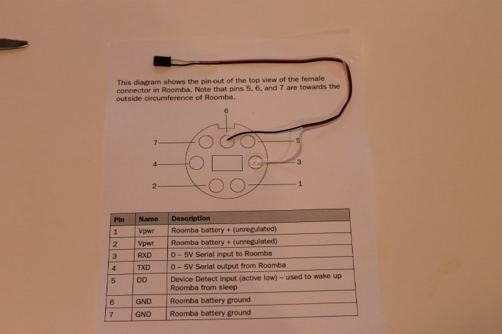
Roomba SCI Cable The cable can have either TX & RX (bidirectional) or just RX connected from the Roomba. However, do note that if only the RX pin is connected, the sensor data will not be read.
Roomba <-> USB <-> PC This cable will allow reading sensor data. iRobot has a low-cost USB cable that can connect directly to a PC. This is useful if the PC is located within the robot. You can get it from here: https://store.irobot.com/default/parts-and-accessories/create-accessories/communication-cable-for-create-2/4466502.html
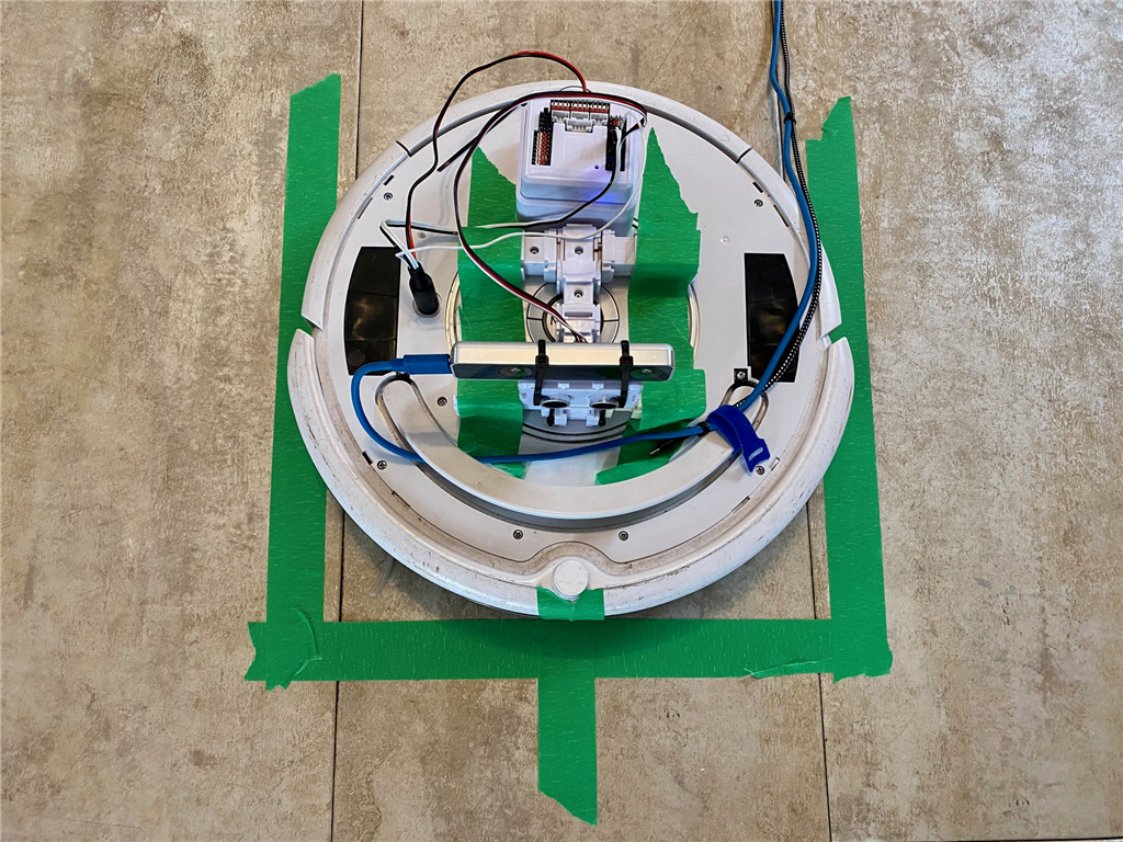
Roomba <-> EZB <-> PC (two-way communication) This cable will allow reading sensor data. This requires a 7 pin Male Mini Din to connect to an EZB I/O Controller. Watch DJ's iRobot Roomba Live Hack to see how to make a cable. The meat of the video starts at 20:00 because the first bit is demonstrating the iRobot Roomba and talking about it. You can find the part numbers and design information for a cable on Synthiam's GitHub repo HERE.
Roomba <-> EZB <-> PC (one-way communication) The image below demonstrates how to make a cable with RX only. Meaning, the sensor data will not be read by ARC.
Charging After SCI Connection When the iRobot Roomba is used with this robot skill, the robot will be put into a mode that will not accept charging. The only way to enable the robot to accept charging is to power off or reset using the two buttons on the control. Pressing either the Reset/Power Off or Power Down buttons will play an acknowledge song if successful.
NMS (Navigation Messaging System) Within the configuration, the menu has an option to enable the NMS (Navigation Messaging System). This will push calculated cartesian position/location (i.e. pose) coordinates into the NMS for use with mapping/navigation tools such as The Navigator. In order to obtain wheel encoder data from the iRobot, a two-way SCI cable is needed (i.e. RX and TX must be connected) and streaming must be enabled.
The iRobot uses wheel encoders (508.8 ticks per revolution) to keep track of the odometry. This robot skill will calculate cartesian coordinates from the wheel encoders and send those values into the NMS. The iRobot's memory will keep the wheel encoder count even when powered off. In order to use the NMS correctly, follow this procedure to clear the iRobot memory and reset the encoder counts.
Get The Navigator robot skill here.
- Visit the iRobot robot skill configuration screen and enable NMS. Also, ensure your connection type is either PC COM Port or H/W UART because those are the only two that allow two-way communication.
*Optionally, you may select the "Pause NMS navigation with sensor detection" checkbox. This will send a pause signal to the selected NMS Level #1 navigator if any of the sensors are triggered.
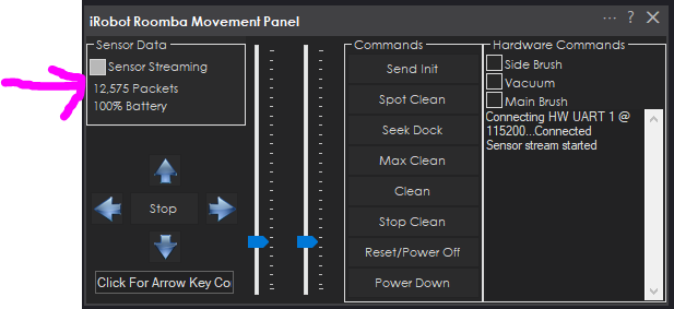
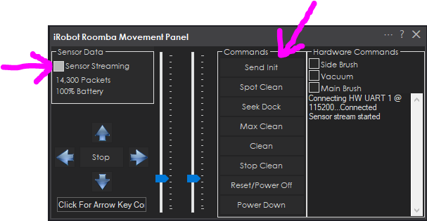
Connect to the iRobot Roomba and enable Sensor Streaming. Verify packets are being received by the packet count increasing in the Sensor Data status display. This step ensures the cable configuration is correctly receiving sensor data from the iRobot Roomba. If the packet count is increasing, the cable configuration is correct.
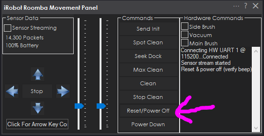
Now we will press the Reset/Power Off button and the robot will play a little tune acknowledging that it has rebooted and reset internal settings. The Sensor Streamer checkbox will disable as well. This step will instruct the Roomba to reset the wheel encoder values which sets the position to 0 cm x 0 cm (home).
Position your iRobot Roomba in the room where 0,0 (home) will be. Good idea to mark the area as well so saved maps can be re-used.
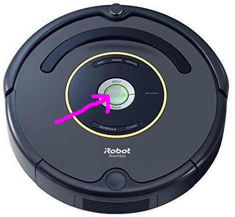
Press the CLEAN button once on the iRobot to power on. It should light up.
In the robot skill, press the INIT button and then enable Sensor Streaming. Again, verify packets are being received. The robot will play a little tune acknowledging that it has been initialized.
If you have The Navigator robot skill added to your project, you will notice the robot will be at location 0,0 (home).
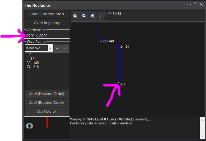
You may now right-click in The Navigator and specify waypoints or drive the robot around and view the trajectory. Read The Navigator for instructions on using that robot skill, as it is not covered in this manual.
Accuracy of Wheel Encoders ... or lack of accuracy is a better title. Wheel encoders are not accurate for mapping but will present a general enough position for simple tasks. This is because there are many limitations to wheel encoder odometry, such as gear slop, slipping wheels and real-world velocities are not constant.
As quoted by Andrew Kramer's work based on Edwin Olson's 2004 paper...
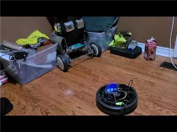
Great Platform Base How about using an iRobot Roomba for your robot wheelbase? You can attach a camera and the EZ-B to a Roomba and turn it into a lean mean cleaning security machine! Combine a USB Joystick and the HTTP Remote Server Control... Voila! Remote control security cleaning robot. That's easy!Quote:
The larger problem is that odometry is inherently inaccurate. Encoder ticks do not translate directly into distance traveled by the wheel because wheels slip, the wheels aren’t perfectly circular, the ground isn’t perfectly flat, encoder ticks might be missed, and the motor gearbox has a backlash that isn’t accounted for in our model. This means that the position calculated from odometry will gradually diverge from the true position. We could use other methods that might be more accurate, such as optical flow and IMUs. However, any sensor we might use suffers from some inherent random error, known as noise, and this error will accumulate over time.
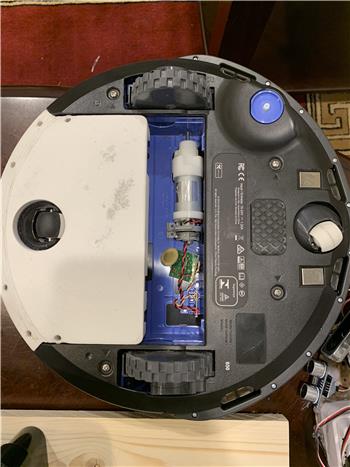
You can use an iRobot Roomba motherboard as an H-Bridge to drive your custom motors. This gives your robot the ability to self-charge. By positioning the IR sensors on your robot in the same fashion as the Roomba, your robot can easily dock with the Roomba's self-charging base.
Related Hack Events
Related Questions
UART TX On Iotiny
Roomba Can´T Connect To PC Without EZ-B
Adding The Caster And Extra Storage To Roomba

Upgrade to ARC Pro
Synthiam ARC Pro is a new tool that will help unleash your creativity with programming robots in just seconds!
Hi DJ, would it be possible to include Roombas sensor data as variables? Speed, distance traveled, bumpers, battery charge, etc?
Yes - the manual on this page explains that sensor data can be read if an RX is connected on the ezb. The ezb must support hardware rx
Was hoping you could include these readings in the next roomba Movement Panel update.
Hello, the data readings are included as variables a few updates ago (months ago from your question). Please read the description for this robot skill at the top of this page. I also had already answered the same question you had asked right above this latest question.
Thanks DJ, will try it as soon as i finish my mini pc build on top of the roomba.
If you’re using a mini pc - then you can actually connect the mini pc directly to the roomba without needing an ezb.
This roomba robot skill has an option to use the PC COM port. Look in the configuration screen to see the settings available
Yes, that is what im going to do, and i am using an "EZDuino" for other IOs.
@DJ, following your advice in another thread, I am taking a look to the Roomba Movement Panel to read the data. I can indeed see a lot of Roomba-related variables when I am connected, however I don't know how to "interpret" them or use them in an "informative" way.
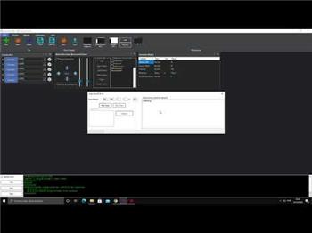
For example, for charging status, i can see in the Variable Watcher:
How can I use the variable to obtain the charging state (Not Charging, Full Charging, Charging Fault, etc.)?
I have the same difficulty with a lot of other variables and I cannot make the link with info available in the Roomba OI manual...
Sorry if the info is somewhere on the website. Thanks