

Control two continuous servos for bidirectional robot movement with speed sliders, configurable ports/stop values, testing and brake/coast options.
How to add the Continuous Servo Movement Panel robot skill
- Load the most recent release of ARC (Get ARC).
- Press the Project tab from the top menu bar in ARC.
- Press Add Robot Skill from the button ribbon bar in ARC.
- Choose the Movement Panels category tab.
- Press the Continuous Servo Movement Panel icon to add the robot skill to your project.
Don't have a robot yet?
Follow the Getting Started Guide to build a robot and use the Continuous Servo Movement Panel robot skill.
How to use the Continuous Servo Movement Panel robot skill
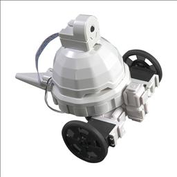
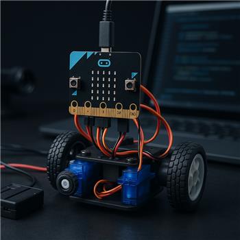
Continuous rotation servos are a popular way to power small robots. You attach a wheel (or tread sprocket) directly to each servo horn and use them like drive motors.
Unlike a standard positional servo (which moves to a specific angle like 0°–180°), a continuous rotation servo spins continuously like a motor. You don’t tell it “go to 120°”—instead you tell it “spin forward”, “spin backward”, or “stop”.
A continuous servo is usually a modified standard servo. Two internal parts are changed so it can rotate 360° forever:
-
Mechanical Stop Removed
A standard servo has a built-in physical stop on the internal gear so it cannot rotate past about 180°. Continuous servos remove that stop so the output shaft can keep turning. -
Potentiometer Disabled/Removed
A standard servo uses a potentiometer (a position sensor) to know its current angle. That sensor can only turn a limited amount. When it’s removed or replaced with fixed resistors, the servo no longer knows its position—so it can’t “hold” an angle anymore. Instead, the input signal becomes a speed/direction command.
Main Window
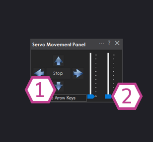
- 1) Movement Panel
-
Use these buttons to drive your robot:
- Forward: both servos spin to move the robot forward
- Reverse: both servos spin to move the robot backward
- Left/Right: one side spins faster or opposite to turn the robot
- Stop: stops movement (behavior depends on a setting explained below)
- 2) Speed Sliders
-
These sliders set the speed for each servo (0–100%). The default is 0%, which means the servo is OFF until you raise the slider.
Why two sliders? Many robots drift left or right because one servo spins slightly faster than the other. You can “trim” the speeds by lowering the faster side.
Note: Not all continuous servos support true variable speed. Some will behave more like “on/off” around certain values, depending on the servo brand and type.
Settings
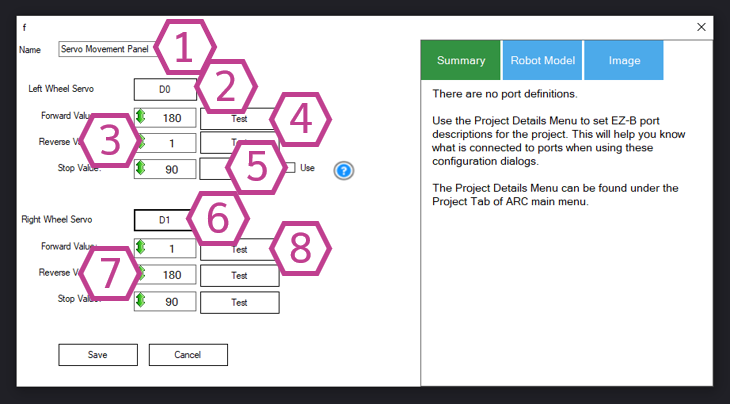
- 1) Title Field
- The name of this skill as it appears in your ARC project. Rename it if you have multiple movement skills and want to stay organized.
- 2) Left Servo Port Drop-down
-
Choose the digital port on the EZ-B where the left continuous servo signal wire is connected (example:
D0). - 3) Left Servo Forward / Reverse / Stop Value Drop-downs
-
Continuous servos still receive “servo position” style signals (1–180), but those values act like speed/direction.
- Stop is usually around 90
- Values above 90 typically spin one direction
- Values below 90 typically spin the other direction
The default example behavior for the left servo is:- Forward: 180
- Reverse: 1
- Stop: 90
- 4) Test Buttons (Left)
- Quickly tests the Left servo using your selected Forward/Reverse/Stop values without switching back to the main window. This is helpful for confirming wiring and direction.
- 5) Use Checkbox (Stop Behavior)
-
This setting changes what happens when you press Stop:
- Unchecked (default): ARC stops sending the PWM signal when you press Stop. The servo will “coast” or stop naturally. This can reduce drifting on some analog continuous servos.
- Checked: ARC keeps sending the PWM signal and uses your Stop value (usually 90). This can feel more like a “brake” because the servo actively holds the stop command.
Beginner tip: If your robot slowly creeps forward or backward when you press Stop, try leaving this unchecked (default). If your robot rolls too far after stopping and you want a firmer stop, try checked. - 6) Right Servo Port Drop-down
-
Choose the digital port for the right continuous servo (example:
D1). - 7) Right Servo Forward / Reverse / Stop Value Drop-downs
-
The right servo is often mounted as a mirror image of the left servo, so its “forward” direction may be reversed compared to the left side.
A common default example for the right servo is:- Forward: 1
- Reverse: 180
- Stop: 90
- 8) Test Buttons (Right)
- Tests the Right servo using the selected Forward/Reverse/Stop values.
Step-by-Step: Getting Your Robot Moving
-
Connect your hardware
Plug each continuous servo into the EZ-B:- Connect the signal wire to a digital port (example: Left =
D0, Right =D1). - Make sure the servos have proper power (follow your EZ-B/servo power recommendations).
- Connect the signal wire to a digital port (example: Left =
-
Add the skill to your ARC project
In ARC go to:Project→Add Skill→Movement Panels→Continuous Servo Movement Panel. -
Choose the correct ports in Settings
Open the skill’s Settings and set:- Left Servo Port to the port your left servo is plugged into
- Right Servo Port to the port your right servo is plugged into
-
Set a speed
On the main window, move both speed sliders above 0% (start around 20–40%). -
Test movement
Press Forward. If the robot goes backward, you can fix it by:- Swapping the Left and Right ports in Settings, or
- Adjusting the Forward/Reverse values for the side that is inverted, or
- Physically swapping which servo is on the left/right side (depending on your build)
- Nothing moves: confirm sliders are not at 0%, confirm correct ports, confirm power to servos.
- Robot turns when trying to go straight: lower the speed slider on the faster side.
- Robot creeps when stopped: adjust the Stop value slightly (e.g., 88–92) or try the Stop checkbox option described above.
Video
Requirements
- 1 x EZ-B I/O Controller
- 2 x Continuous Servos
Resources
- Learn how ARC Movement Panels work: https://synthiam.com/Docs/ARC-Overview/movement-panels
- Servo technical overview: Servo Tutorial
Related Tutorials
Calibrate Continuous Rotation Servo And Adjust Speed
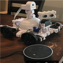
Using Amazon Echo (Alexa) As Microphone For Synthiam
The Robot Program Episode 012: Getting Adventurebot To Move
Related Hack Events

D-0 Droid Live Hack

D-0 Droid Live Hack Part 2
Related Robots
Related Questions
JD On A Chassis With 2 X 360 Servo But Only One Movement...
Micro:Bit Continuous Servos Jittering

Upgrade to ARC Pro
Don't limit your robot's potential – subscribe to ARC Pro and transform it into a dynamic, intelligent machine.
Is there a way to modify the controls to change the direction of the servos? To go forward, you have the right servo rotating clockwise and the left rotating counter-clockwise, and this works perfectly fine if the drive wheels are attached directly to the servos. However, since I'm trying to hack a Robie Sr. and I want to use its original FOUR wheels, this demands that I attach each servo to a gear that drives two wheels on either side in the opposite direction of which the servos are rotating. I thought that a simple solution to this problem would be to simply swap ports with the servos, and this DOES make the robot drive forward and backward with its respective Forward and Backward commands like it's supposed to... but when it comes to TURNING, the servos still rotate in the opposite direction just the same as if they were in their INTENDED ports. It drives forward like it's supposed to, it drives backward like it's suppose to, but the Left button makes it turn right, and the Right button makes it turn left.
Is there a way to invert these controls? Or would I be better off just using the TWO wheels that came with the developer kit and installing a couple of small caster wheels in the back for balance?
(I apologize for asking so many dumb questions, I don't know why I get so easily lost in here. )
)
Change the values for the directions of each servo.
right now, the forward sends a command of some number. And reverse sends the opposite number. Those numbers are degrees. Reverse them
That was it. Thank you again!