
Hector SLAM-based ARC navigator that maps with lidar/depth, saves waypoints, plans paths and autonomously navigates while avoiding obstacles.
How to add the The Better Navigator robot skill
- Load the most recent release of ARC (Get ARC).
- Press the Project tab from the top menu bar in ARC.
- Press Add Robot Skill from the button ribbon bar in ARC.
- Choose the Navigation category tab.
- Press the The Better Navigator icon to add the robot skill to your project.
Don't have a robot yet?
Follow the Getting Started Guide to build a robot and use the The Better Navigator robot skill.
How to use the The Better Navigator robot skill
The Better Navigator
A better navigation skill based on Hector SLAM using ARC's NMS location/positioning and obstacle data. This skill is combined with other skills contributing navigation data to ARC's Navigation Messaging System (NMS). The lidar or depth camera data will create a map of the room(s) as the robot drives. You can then add waypoints that are saved with the project. You can have the robot automatically navigate by clicking on a waypoint (i.e., kitchen, sofa, or dining room). The robot will figure out a path to get there and avoid obstacles.
Tutorial

Sensor Requirements
This robot skill uses data submitted to the NMS. It requires a positioning source (Layer 3 Group 2) and a depth/lidar sensor (Layer 3 Group 1). Check the NMS manual for a list of sensors you can use for this skill. You need a Layer 3 Group 1 and Layer 3 Group 2 sensor. Pick one from each group to be used in this skill. Here's the NMS manual: https://synthiam.com/Support/ARC-Overview/robot-navigation-messaging-system
Positioning Sensor (NMS L3G2)
This robot skill requires data for the SLAM pose hint. This is a suggested position where the SLAM should start looking in its map for where the robot might be. Depending on the depth sensor you are using, the internal Hector SLAM can be used as the pose hint instead of a pose sensor.
If you wish to use a pose sensor, the best sensor is the Intel RealSense T265. This robot skill's algorithm will fuse the positioning sensor's data with the SLAM pose data, providing high accuracy of pose telemetry. You may also have good pose prediction with a wheel encoder NMS, such as the iRobot Roomba. The NMS Faux Odometry will most likely not provide accurate pose data.
If you wish to use the internal Hector SLAM to provide its pose hint, that can be done with supporting sensors. For example, the Hitachi and RPI Lidar both have an option to fake the pose hint event. In this case, you can set the configuration of this robot skill pose hint to HECTOR and use only those lidar sensors.
Depth/Lidar Sensor (NMS L3G1)
This robot skill requires the NMS to have depth avoidance sensors providing multiple data points, such as a 360 degree Lidar, Intel RealSense Depth Camera, or Microsoft Kinect. This means ultrasonic distance sensor data does not give enough scan points for this robot skill but can be added for additional scan information.
Example
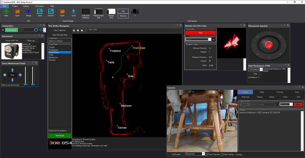
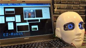
This screenshot uses an Intel RealSense T265 with a 360-degree lidar sensor. The robot was instructed to drive around the waypoints at various speeds.
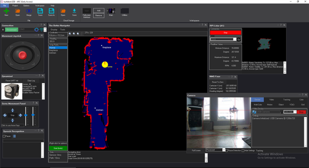
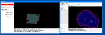
This screenshot uses only an RPI Lidar. The RPI Lidar robot skill is set to fake the pose hint event. And The Better Navigator is configured to use the HECTOR as the pose hint.

ARC Navigation Messaging System
This skill is part of the ARC navigation messaging system. It is encouraged to read more about the Navigation Messaging System and learn compatible skills. This particular skill (The Better Navigator) operates on Level #1 of the NMS overview. This skill (The Better Navigator) requires a Level #3 Group #2 location/position sensor for operation. The location/positioning system will feed position data into the NMS, which this skill will use for navigation. See the NMS for compatible skills that provide location/position data.

Mapping
While your robot is driving around and navigating, this skill will log the trajectory. You define the waypoint and path points by manually driving your robot to various locations (waypoints). Once multiple path points are defined for a waypoint, you can instruct your robot to autonomously navigate to that exact waypoint (or back again) at any time.
Map Size
The map is currently hardcoded for 20x20 meters.
Main Screen
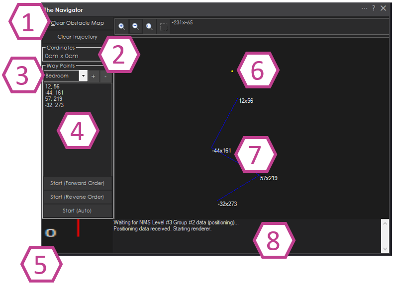
- Map control buttons for clearing trajectory and clearing the map.
- The robot's current cartesian coordinates as reported by an NMS Level #3 Group #2 sensor (i.e., Intel T265, wheel encoders).
- Saved waypoints. Here you can add, remove and select waypoints.
- The path points within a waypoint. A waypoint will consist of many path points for navigating throughout the environment. You may right-click on path points to edit the coordinate for fine-tuning. You may also re-order the path points by right-clicking and selecting Move Up or Move Down.
- Current heading of the robot relative to the cartesian starting position as reported by an NMS Level #3 Group #2 sensor.
- The yellow dot marks the robot's current cartesian position as reported by an NMS Level #3 Group #2 position/location sensor.
- Path points are connected with a straight line demonstrating where the robot drives. Right-click on the map view and select Add Path Point to add path points. It is best to drive the robot, which creates a trajectory. Then, right-click on some points of the trajectory to add new path points to the selected waypoint.
- Log messages are displayed about navigation and sensor activity.
Main Screen - Navigation Controls
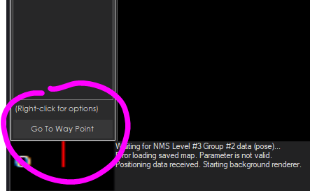
This button manually starts navigating to the selected waypoint. You may also begin navigating by using ControlCommands from other skills. When the robot is navigating, this button behavior changes to stop navigating.
Configuration
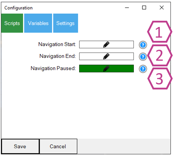
Config - Scripts
| # | Setting | Description |
|---|---|---|
| 1 | Navigation Start | Script that will execute when the navigation to a waypoint is started. Navigation can begin by manually pressing the Start button or using a ControlCommand(). |
| 2 | Navigation End | Script will execute when the navigation is canceled or successfully ended. |
| 3 | Navigation Paused | If the navigation is paused by a JavaScript/Python command from the Navigation namespace, or if the pause is triggered by the NMS Level #3 Group #1 distance sensor returning a value less than the specified range (configured in the Navigation tab), this script will execute. |
Config - Variables
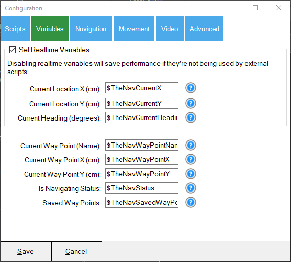
Many global variables are set for The Better Navigator. A question mark next to each variable explains in greater detail. The variable contents can be viewed using the Variable Watcher skill found in the Scripts category. The option to uncheck Set Realtime Variables will save on performance if the variables are not used in your custom scripts. This data is available in the NMS scripting engine namespace anyway.
Set Realtime Variables
Checkbox group that enables/disables realtime variable updates. Disabling realtime variables will save performance if they are not being used by external scripts.
| Setting | Description |
|---|---|
| Current Location X (cm) | Variable name for the robot's current X position in centimeters. |
| Current Location Y (cm) | Variable name for the robot's current Y position in centimeters. |
| Current Heading (degrees) | Variable name for the robot's current heading in degrees. |
Waypoint Variables
| Setting | Description |
|---|---|
| Current Way Point (Name) | Variable name for the name of the waypoint currently being navigated to. |
| Current Way Point X (cm) | Variable name for the X coordinate of the current target waypoint in centimeters. |
| Current Way Point Y (cm) | Variable name for the Y coordinate of the current target waypoint in centimeters. |
| Is Navigating Status | Variable name for the current navigation status (whether the robot is actively navigating). |
| Saved Way Points | Variable name (array) for the list of saved waypoints. |
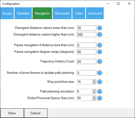
Config - Navigation
| # | Setting | Range | Description |
|---|---|---|---|
| 1 | Disregard distance values lower than (cm) | Integer | Ignore distance values less than this specified distance in CM. The distance values are provided by any NMS Level #3 Group #1 sensor. If wires or a camera block the sensor, this will ignore those values. |
| 2 | Disregard distance values higher than (cm) | Integer | Ignore distance values further than this specified distance in CM. The distance values are provided by any NMS Level #3 Group #1 sensor. Many sensors are inaccurate at far distances so you can ignore those values. |
| 3 | Pause navigation if distance less than (cm) | Integer | Any navigation will be paused if the NMS distance sensor provides a value greater than the "lower than" but lower than this. This will also execute the PAUSE script from the Scripts tab. Your program may use this opportunity to navigate the obstacle and continue navigating again. Use the Javascript or Python command in the Navigation namespace to continue navigating: Navigation.setNavigationStatusToNavigating() |
| 4 | Pause navigation degree range (degrees) | Integer | This value complements the pause navigation distance value. It determines the degree range of when to pause navigation. If you wish to pause the entire range, enter 360 degrees. If you only want objects in front of the robot paused, enter 90. The degree number entered is divided by two and used from the left and right of the center of the robot. For example: 90 degrees = 45 left + 45 right; 180 degrees = 90 left + 90 right; 360 degrees = full range detection. |
| 5 | Trajectory History Count | Integer | Like a snake trail, a trail is left behind the robot's navigation. We keep a certain number of history positions. Otherwise, the trail will be gone forever and clutter the map. |
| 6 | Number of pose frames to update path planning | Integer | The path planning will only update every X frames from the L3G2 pose telemetry sensor to save CPU usage. |
| 7 | Way-point font size | 5 - 50 | The size of the font for the waypoint titles. You may change the font size depending on how zoomed you are on the map. |
| 8 | Path planning resolution | 2 - 20 | A path consists of many micro-waypoints. This is the resolution of how many waypoints to create. A value of 2 would mean every 2 CM is a new waypoint, and 20 would mean every 20 CM is a new waypoint. The higher the number, the fewer waypoints and the less correcting the robot would need to make. However, if the value is too high, corners will be cut too close, and the robot may come in contact. |
| 9 | Robot Personal Space Size (cm) | 10 - 200 | This is a robot's personal space size bubble to keep from walls and objects when path planning. A value of 50 would be 50 CM square. If this value is too large, the robot may not have enough room to navigate and reach destinations. If the value is too small, the robot may touch the wall or objects. |
| 10 | Path plan iterations | 1 - 100,000 | Number of iterations for the path planning algorithm. Higher values may find better paths but take longer to compute. |
| 11 | Log Odds Occupied Max | 1 - 200 | Maximum log-odds value a cell can reach. Higher values make occupied cells more persistent but slower to clear. Default is 50. |
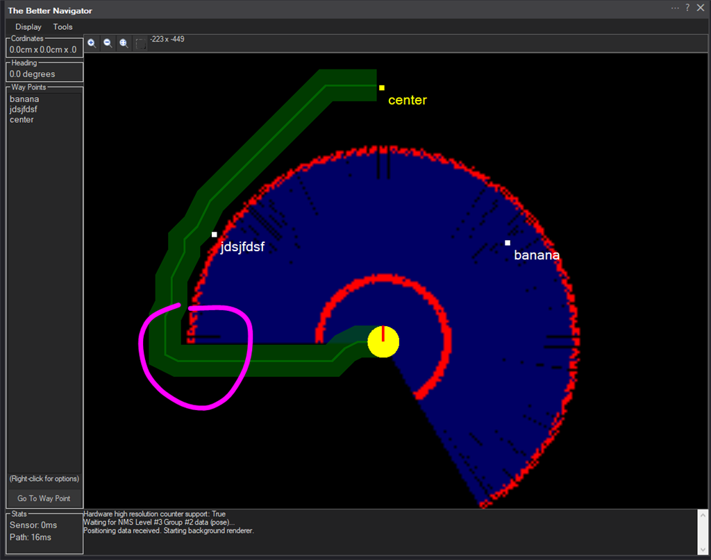
Path Planning Resolution Examples
Here is an example of a resolution of 2:
Here is the same example of a resolution of 20:
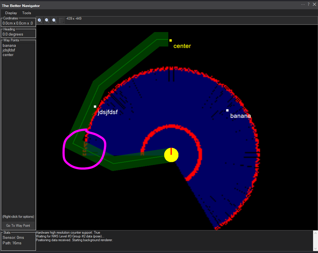
You can see how the lower resolution (higher value) caused the robot to drive into the corner. Having many micro waypoints causes the robot to correct more often and also prevents it from hitting corners. Finding a balance for your environment requires testing.
Config - Movement
Basic Movement
| # | Setting | Range | Description |
|---|---|---|---|
| 1 | Forward speed while navigating | 1 - 255 | When navigating to a waypoint, this is the speed for the forward movement. You do not want the robot to move too quickly when navigating, as this increases pose telemetry accuracy. By moving too quickly, the robot will lose position. Have the robot move as slowly as you can to improve accuracy. |
| 2 | Turn on the spot speed while navigating | 1 - 255 | Similar to the Forward speed, this is used for turning when navigating. If the robot turns too quickly, the navigation sensor may not be able to keep up, causing many course corrections. Slower turning is recommended. |
| 3 | Degrees of forgiveness while turning | 1 - 300 | When navigating to waypoints, a path is calculated consisting of many minor waypoints. The robot must turn toward the next waypoint before moving forward. This is the number of degrees of forgiveness for how accurate the robot must be facing. Many robots do not have the accuracy when turning, especially if they turn too quickly, so you would want this number to be higher. This value must be increased if the robot bounces back and forth, attempting to line up the next waypoint. |
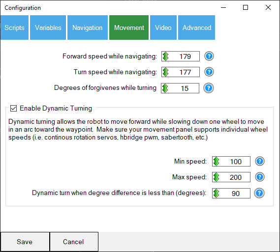
Enable Dynamic Turning
| # | Setting | Range | Description |
|---|---|---|---|
| 4 | Enable Dynamic Turning | Checkbox | This will allow the robot to turn using radial symmetry toward the object rather than rotate on the spot. This requires the Movement Panel to support individual wheel speed control, such as the continuous rotation servo, H-bridge PWM, Sabertooth, Dynamixel wheel mode, etc. |
| 5 | Min speed / Max speed | 1 - 255 | The minimum (slowest) and maximum (fastest) speed for turning. For example, if turning hard left, the left wheel would spin at the min speed (slowest), and the right wheel would spin at the max (fastest) speed. The value between the min and max is used to dynamically calculate how much speed the wheels need to turn in an arc. |
| 6 | Dynamic turn only when degree difference is less than (degrees) | 1 - 255 | The robot will use dynamic turning if the next waypoint is less than this value of degrees. Otherwise, if the turn difference exceeds this value, the robot will use standard on-the-spot turning. If the waypoint is 180 degrees behind the robot, spinning on the spot toward the waypoint would be more efficient. Otherwise, if the waypoint is 30 degrees to the right, drive toward the waypoint on a slight radial path. |
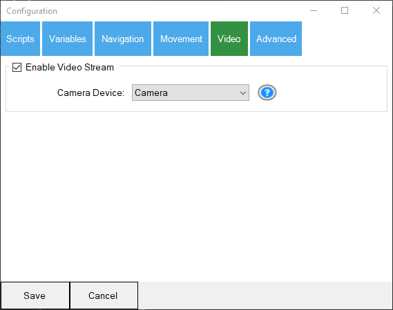
Config - Video
| # | Setting | Description |
|---|---|---|
| 1 | Enable Video Stream | Checkbox to enable/disable video stream output. The output of the map can be sent to a camera device. The camera device must be started and in CUSTOM mode. The Custom can be selected in the device dropdown. This is useful if the map is displayed in a custom interface screen or PiP in Exosphere. |
| Camera Device | Select a camera device to direct the map output to. A camera device must be selected if video stream is enabled. |
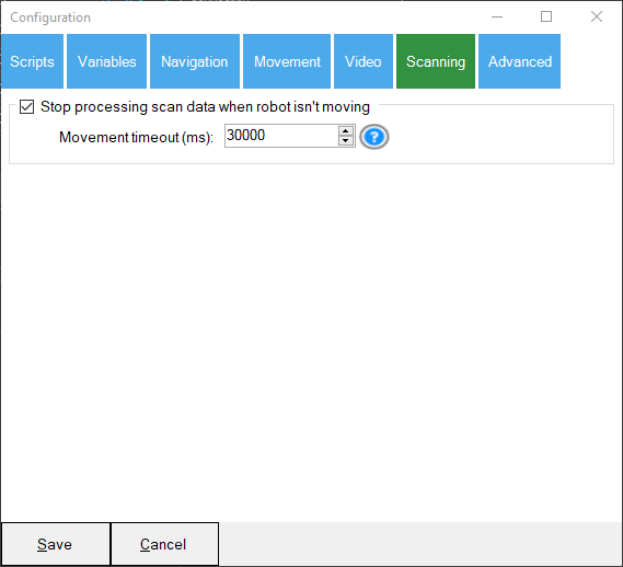
Config - Scanning
| # | Setting | Range | Description |
|---|---|---|---|
| 1 | Stop processing scan data when robot isn't moving | Checkbox | This checkbox will instruct the navigator to stop processing scan data when the robot isn't moving. This is useful when your robot experiences sensor drift after staying stationary for too long. It is noticeable with some pose sensors and when using the Hector pose hint. |
| 2 | Movement timeout (ms) | 1 - 99,999,999 | How long the navigator should continue processing scan data after stopping the robot. This value is not used unless the Stop Processing scan data checkbox is checked. This value is in milliseconds. So, if the robot stops moving and this value is set to 30,000 ms, the navigator will stop processing scan data after 30 seconds. It will begin processing scan data immediately when the robot starts moving again. |
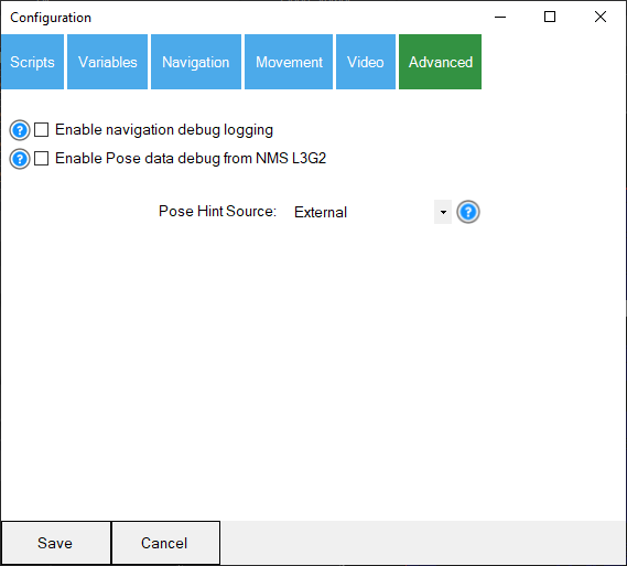
Config - Advanced
| # | Setting | Description |
|---|---|---|
| 1 | Navigation debugging | Outputs a noisy log when navigating the distances and degrees needed to turn. Do not use this if you're trying to save on performance. |
| 2 | Pose data debugging | Output information about pose data received from the NMS. This is a very noisy log and not recommended for saving on performance. |
| 3 | Pose Hint Source | Selects the source type for pose hints used by the SLAM system. See the Pose Hint Types section below for detailed descriptions. |
Pose Hint Types
The Pose Hint Type determines the source of positional data (pose) used by the SLAM system to predict and refine its location. Each type leverages different data sources and methodologies to balance accuracy, reliability, and real-time responsiveness. Below are detailed descriptions of each type:
1. Hector
- Description: The pose is derived exclusively from the Hector SLAM algorithm. This type relies on LiDAR (or similar) data to determine the robot's location by matching scans with the current map.
- Use Case: Ideal when no external sensors (e.g., odometry) are available or if the SLAM algorithm is sufficiently robust to operate independently.
- Strengths:
- No dependency on external hardware.
- Works well in environments with distinct and abundant features for scan matching.
- Limitations:
- Can struggle in featureless areas or when the robot undergoes rapid, untracked movements.
2. External
- Description: The pose is derived entirely from an external sensor, such as wheel encoders, an inertial navigation system (INS), or devices like the Intel RealSense T265. SLAM does not rely on LiDAR scan matching in this mode.
- Use Case: Best for scenarios where external pose sensors are reliable and accurate, such as smooth surfaces or predictable movements.
- Strengths:
- Simple and fast computation, as no LiDAR scan matching is performed.
- Can be highly accurate when external sensors are properly calibrated.
- Limitations:
- Prone to drift over time without correction.
- Errors can accumulate due to wheel slippage or sensor inaccuracies.
3. Average
- Description: The pose is calculated as the average of the Hector SLAM pose and the External pose. It provides a balanced estimate that considers both sources equally.
- Use Case: Useful when Hector SLAM and External sensors are equally reliable and when blending their inputs can reduce individual weaknesses.
- Strengths:
- Smooths out discrepancies between Hector and External poses.
- Provides a compromise between computational complexity and accuracy.
- Limitations:
- Errors from either source can still influence the average.
- Not ideal when one source is significantly less reliable than the other.
4. Differential
- Description: The pose is derived by applying the difference between the last and current External pose to the last known Hector pose. This method leverages external data for incremental updates.
- Use Case: Works well in environments where external sensors are reliable for detecting small movements, but Hector SLAM provides the base reference for global accuracy.
- Strengths:
- Allows for precise incremental corrections.
- Reduces reliance on external sensors for absolute positioning.
- Limitations:
- Requires consistent and accurate external pose updates.
- Errors in the incremental updates can accumulate if not corrected.
5. Fused
- Description: Combines Hector SLAM and External poses using weighted confidence values. This type uses a proportional blend of the two data sources, giving higher confidence to the more reliable input. The weights are 70% of the Hector pose and 30% of the external pose.
- Use Case: Ideal for environments with varying reliability of SLAM or external sensors. For example, Hector SLAM can dominate in feature-rich areas, while External sensors compensate in featureless zones.
- Strengths:
- Dynamically balances between Hector and external inputs based on confidence.
- Reduces the impact of errors from a single source.
- Limitations:
- Requires careful tuning of confidence weights.
- Slightly more computational overhead compared to simpler types.
6. Dynamic
- Description: Incrementally adjusts the last Hector pose using the difference between the current and previous External poses and fuses them with a 60% Hector and 40% external. This approach ensures the Hector pose is continuously updated, maintaining a smooth and responsive trajectory.
- Use Case: This is effective for scenarios where external odometry captures the robot's movement well, but the global accuracy of Hector SLAM is still necessary.
- Strengths:
- Provides continuous updates without heavy reliance on SLAM processing.
- Mitigates drift by keeping the pose updated in real time.
- Limitations:
- Requires accurate and frequent updates from external sensors.
- Errors in external pose deltas can propagate to the adjusted Hector pose.
Choosing the Right Pose Hint Type
| Type | Best For | Limitations |
|---|---|---|
| Hector | SLAM-only setups, feature-rich environments | Struggles in featureless areas or during rapid movements |
| External | Odometry-reliable setups | Prone to drift and lacks map-based corrections |
| Average | Balanced inputs from Hector and External sources | Errors from both sources can influence the pose |
| Differential | Incremental corrections with odometry data | Requires accurate and consistent external pose updates |
| Fused | Dynamic environments with varying sensor reliability | Slightly higher computational cost due to blending logic |
| Dynamic | Real-time updates with odometry corrections | Errors in odometry deltas can propagate to the final pose |
Pose Hint Suggestions
We have a few suggestions for the pose hint value based on your robot's sensor configuration.
360 Degree Lidar Only (recommended)
- The Better Navigator Pose Hint should be set for Hector
- The 360-degree lidar configuration should be set to Fake Pose Hint Event (checked)
360 Degree Lidar with NMS L3G2 Pose Sensor (i.e., Wheel encoder, T265, etc.)
- The Better Navigator pose hint should be set for Dynamic
- The 360-degree lidar configuration should not set a fake pose hint event (unchecked)
- The downfall to this sensor configuration is that the pose sensor can still result in mapping errors. This is noticeable when the map begins to shift.
Depth Camera (i.e., Kinect, RealSense, etc.) with NMS L3G2 Pose Sensor (i.e., Wheel encoder, T265, etc.)
- The Better Navigator pose hint should be set for Fused
- The downfall of this sensor configuration is that the depth camera does not provide enough data points for the SLAM to produce a pose hint. That means you will rely solely on the external NMS L3G2 pose sensor, which will increase errors over time. The solution is to combine the depth camera with a 360-degree lidar.
360 Degree Lidar, Depth Camera (i.e., Kinect, RealSense, etc.) with NMS L3G2 Pose Sensor (i.e., Wheel encoder, T265, etc.)
- The Better Navigator pose hint should be set for Dynamic
- The 360-degree lidar configuration should not set a fake pose hint event (unchecked)
Starting Position
This navigation skill uses cartesian coordinates in CM from the starting position (0, 0). Any saved maps will be referenced from the same starting position and heading angle. When you re-load a project to have the robot navigate the same course, the robot must be positioned in the same starting position and heading angle. We recommend using painter/masking tape as the starting reference point for the robot. If your robot has an auto dock for charging, secure the charger to a fixed position on the floor, which can be used as a reference point.
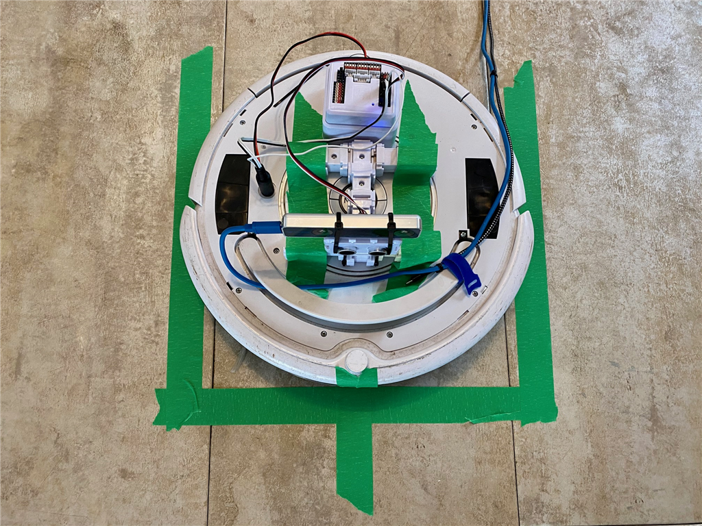
We're using an iRobot Roomba as the robot with an Intel T265 positioning sensor in the photo above. The painter's tape on the floor marks the robot's starting position. The outline allows us to position the robot in the square, and the marking on the front of the robot aligns with the specified heading.
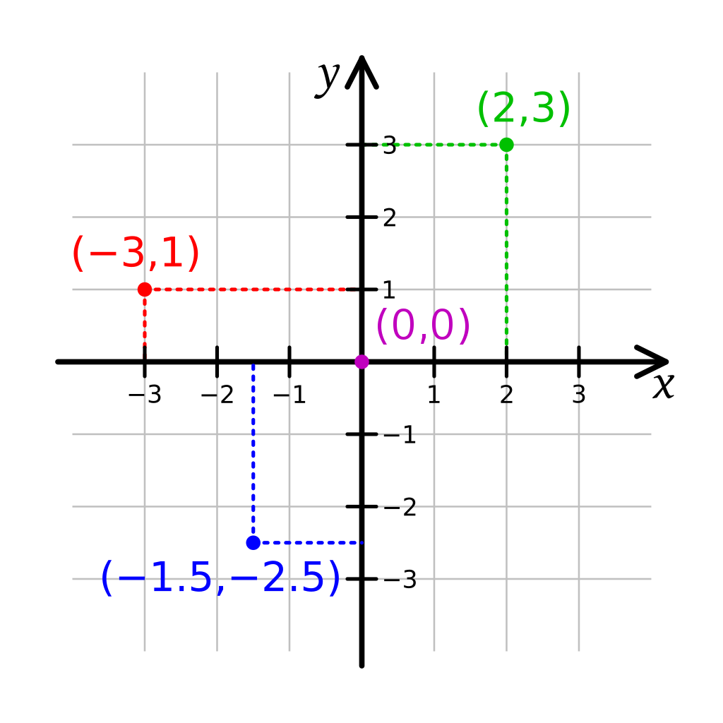
Cartesian Coordinate System
This robot skill uses cartesian coordinates to reference the robot's starting position. The starting position is always 0,0 and is defined at startup. As the robot navigates, the skill measures the distance from the starting position. The unit of measurement is in CM (centimeters). Read more about the cartesian coordinate system on Wikipedia.
Example #1 (360 degree lidar only)
We'll use only a 360-degree lidar with this skill for navigation and mapping. Here's a screenshot of this type of setup. The Movement Panel is continuously rotated and uses Robotis Dynamixel servos. However, any Movement Panel will do. The 360-degree lidar is RPI Lidar A1.
Note: This example assumes you already have a movement panel, and the robot can move.
- Connect your lidar to the PC via the USB cable
- Add the respective lidar robot skill to the project (in this case, we're using an RPI Lidar A1)
- Configure the lidar robot skill and select the Fake Pose Hint Event option (read the manual for the lidar robot skill for more information on that option)
- Add The Better Navigator robot skill to your project
- Configure The Better Navigator and select the pose hint to be HECTOR
- Start the lidar robot skill
- The map will begin to fill. You can now slowly drive the robot around and watch the map continually fill
- Right-click on the map and select areas to navigate to
Example #2 (Intel RealSense T265 & 360 degree lidar)
To get sensor data for mapping, other skills must be loaded that are compatible. In this quick example, we'll use the Intel RealSense T265 and 360-degree Lidar in combination with this skill. Here's a screenshot of this type of setup. The Movement Panel is continuous rotation which uses Robotis Dynamixel servos. The 360-degree lidar is the Hitachi. However, any Movement Panel will do.
Note: This example assumes you already have a movement panel, and the robot can move.
- Connect your Intel RealSense T265 to the computer's USB port
- Connect the distance sensor of choice (i.e., 360-degree lidar)
- Load ARC
- Add the Intel RealSense skill to your workspace, select the port, and press Start
- Add the 360-degree lidar robot skill to your workspace. Select the port and press Start
- Now, add this skill (The Better Navigator) to your workspace
- Configure The Better Navigator and specify the Pose Hint to be Differential
- You will now see localization path and distance data from the Intel RealSense sensor displayed in The Better Navigator window. This robot skill will be displaying and rendering the data
Example #3 (Interact With Speech Recognition)
The list of waypoints is added to an array. That array can be used with the WaitForSpeech() command in EZ-Script, JavaScript, or Python. This example shows how to use it with JavaScript. Add this code snippet to a speech recognition phrase script. In this example, the phrase we'll add to the speech recognition robot skill is "Robot go somewhere."
Audio.sayWait("Where would you like me to go?");

dest = Audio.waitForSpeech(5000, getVar("$TheNavSavedWayPoints"))

if (dest != "timeout") {

  Audio.say("Navigating to " + dest);

  ControlCommand("The Better Navigator", "GoToWayPoint", dest);
}
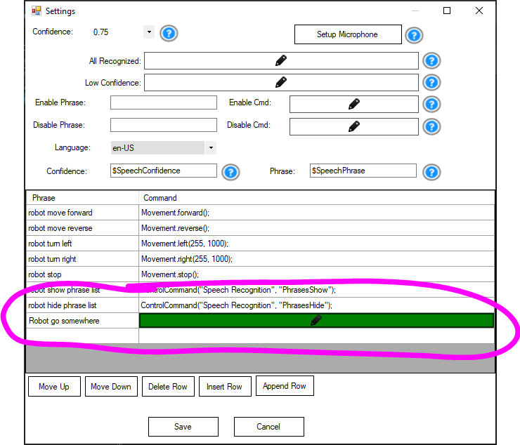
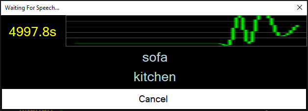
With the code inserted, speak the phrase "Robot go somewhere." The robot will speak, "Where do you want me to go?" and display the list of stored waypoints. Speak one of the waypoints, and the robot will begin navigating.
Troubleshooting
Q: The map appears incomplete.
A: The robot moves too quickly, and the SLAM cannot collect enough frame data to assemble the map. This happens if the robot moves too fast relative to the speed of the lidar.
Q: The robot jumps to different locations on the map.
A: The map is incomplete because the SLAM could not collect enough environmental information. Therefore, the robot skips to where the SLAM thinks the robot is. This can be fixed by having the robot move slower to collect more map data. The more map data (frames), the better.
Control Commands for the The Better Navigator robot skill
There are Control Commands available for this robot skill which allows the skill to be controlled programmatically from scripts or other robot skills. These commands enable you to automate actions, respond to sensor inputs, and integrate the robot skill with other systems or custom interfaces. If you're new to the concept of Control Commands, we have a comprehensive manual available here that explains how to use them, provides examples to get you started and make the most of this powerful feature.
Control Command ManualcontrolCommand("The Better Navigator", "AdjustRobotPose", newX, newY, newDegrees)
- move the robot's pose on the map tot he specified X, Y and degree heading. This is used to adjust the robot to a known location on the map for auto correcting. If you have glyphs or known way points that the robot can identify, you can use those to re-align the map for the robot. This method ensures the map and robot are in sync to avoid any drifting.
controlCommand("The Better Navigator", "CreateNewWayPoint", "WayPointName")
- Create a new waypoint at the current location with the WayPointName as a parameter. Programmatically you can have the robot save the current waypoint as a desired name.
controlCommand("The Better Navigator", "GoToLocation", "x", "y")
- Instruct the robot to navigate to the specific X and Y location on the map. If the path planning is enabled, the navigation will be determined by using that.
controlCommand("The Better Navigator", "GoToWayPoint", "Home")
- Instruct the robot to navigate to the specific saved waypoint by its name on the map. If the path planning is enabled, the navigation will be determined by using that.
controlCommand("The Better Navigator", "StopNavigating")
- Stop the navigation that is currently in process.
Related Questions
True Autonomous Find, Pick Up And Movemovement
Rplidar A1 And Better Navigator

Upgrade to ARC Pro
Your robot can be more than a simple automated machine with the power of ARC Pro!
This initial release does not have the path planning implemented yet. There are also several silly issues with navigating.
The neat thing is if a lidar or depth camera is used, the odometry can be assisted with either Faux Odometry robot skill or wheel encoders. It has much better pose estimation than The Navigator robot skill.
I laughed when I saw the name of this. It reminds me of file naming structures in our past File - New - New.
Will there be a "Best Navigator" or "Better Better Navigator" skill? Kidding!
Back on topic, I'm really looking forward to using this skill!
@DJ Question for you, I have a LIDAR sensor that I'd like to see supported in ARC. It is a different brand than all the rest and is even a lower cost than the Hitachi. How should I go about getting it supported in ARC? Should it have its own skill (as the protocol is likely unique)? Should I look for a developer here in the community to make a skill or contract Synthiam? What do you recommend?
Ya you make a robot skill for it. You can use the hitachi lidar source code as example to build from. Get the source code the hitachi lidar from the robot skill manual page
Updated to use the traditional red color.
Display the cartesian coordinates from the Hector slam estimated pose. The NMS odometry is fused with the hector telemetry pose.
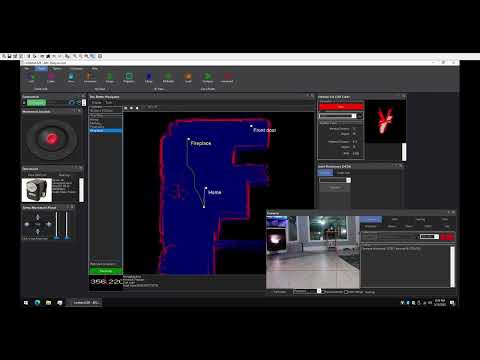
Here's a video of the SLAM path planning for The Better Navigator. This should be included in the next update within two weeks. Rather than defining waypoints, such as The Navigator, you now provide destinations only. The robot will navigate to the goals by automatically determining the most appropriate path.
In this video, the robot is not moving, and the starting position is Yellow in the bottom left. As I click around the scanned map, the algorithm will find the best path to the destination.
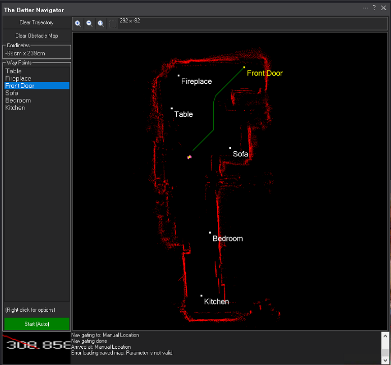
Updated with ability to save way points and path planning prediction. The way points can't execute the path yet - that's the next step. Right now you can select points on the map (right-click) and add way points or select areas to navigate to
Hi DJ I started to test and I see nice improvements over past navigator, the map that now creates is much better and precise (using Intel realsense technology in my case). I really see a good future for this skill. Thanks.
Did you try right-click and add way points to see the auto generated path planning? Pretty wild