EZ-InMoov Robot Head

EZ-InMoov Robot Head by EZ-Robot & Gael Langevin

Connection Type
Wi-Fi
Number of servos
8
Audio Support
Yes
Camera Support
Yes

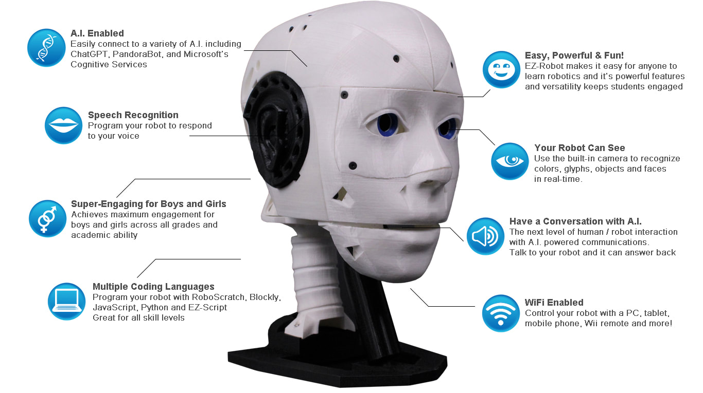
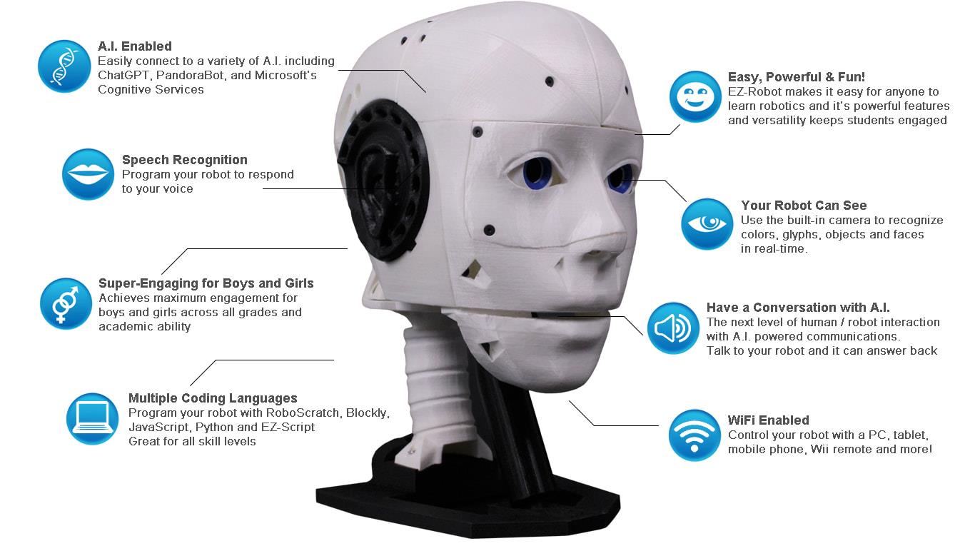
The EZ-InMoov Humanoid Head is a do-it-yourself educational robot head designed for enthusiasts, educators, and researchers interested in artificial intelligence and human-robot interaction. It is a remix of the InMoov head by Gael Langevin, optimized for integration with EZ-Robot products.


Why Use the EZ-InMoov Robot Head?

  • Educational Value: It serves as a hands-on educational tool for learning about robotics, AI, and programming. Experience GPT such as Open AI Chat GPT 4 and more.
  • Research Applications: It can be used for university-level AI research, particularly in the field of human-robot interaction.
  • Ease of Assembly: The kit includes all necessary components and the design is simplified for easy assembly without soldering.
  • Customization: Open-source 3D files allow for customization and personalization of the robot head.
  • Software and AI: Powered by Synthiam ARC, it supports a range of AI features, including vision tracking, speech recognition, and chatbot integration.
  • Programming Flexibility: Users can program the robot using JavaScript, Python, or Blockly, making it accessible to a wide range of skill levels.
  • Mobile App Control: The head can be controlled via a mobile app for convenience.
  • Emotional Intelligence: It can be used for research into emotion detection using Microsoft cognitive services.
  • Versatility: The head can be powered by a battery for portability or a wall adapter for continuous use.


Key Features

  • Seamless Integration: Designed to attach easily to an InMoov body.
  • Complete Component Package: All hardware and electronics included.
  • Simplified Design: Fewer parts, unified internal bracket, and simplified eye assembly.
  • Portability: Electronics and battery fit within the skull for a self-contained unit.
  • Enhanced Movement: Improved eyeball movement and head side-to-side movement.
  • Immersive Audio: A ported voice box and small speaker for vibrant sound.
  • IoTiny Integration: Wireless control through IoTiny Robot Controller.
  • Comprehensive Software Suite: Broad AI experimentation with Synthiam ARC.
  • Advanced AI Capabilities: Supports vision tracking, text-to-speech, and speech recognition.
  • Emotional Intelligence: Capable of human emotion detection research.


Downloads


Details

The EZ-InMoov Robot Head is ideal for those looking to delve into the world of robotics and AI with a hands-on, customizable, and educational platform. It offers a unique blend of accessibility and advanced features, making it a compelling purchase for hobbyists, educators, and researchers.


EZ-InMoov Robot Head FAQ

Q: What 3D printing material and settings do you recommend?
A: We recommend using PLA plastic with a 0.4mm nozzle, two shells, 30% diamond (or grid) infill, a raft, and no supports. The parts that need support have custom supports integrated into the design.

Q: How long will it take to 3D print all the parts needed for the EZ-InMoov Robot Head?
A: This depends on the travel speed and reliability of your printer(s). With two printers with a travel speed of 150 mm/s, you can print all the parts in 2-3 days. If you have a single printer with a 60 mm/s travel speed, printing all the parts may take 5-7 days.

Q: Is any soldering required to put this kit together?
A: Nope, it's plug-and-play!

Q: Can I power the head directly from a wall power adapter?
A: Yes. If you're using the robot head in a stationary setting, you can use our 7.5v power adapter.

Q: Why did my camera or servos stop working?
A: When the head moves, the servo and camera wires have the potential to snag and pull away from their connections. Plug the connectors back into their designated positions and rerun the wire. We recommend running the wire straight over the jaw pivot cup and back to the IoTiny. Place the excess wire length in the cavity at the back of the skull.

Q: A servo doesn't seem to have a full range of motion; what gives?
A: The EZ-InMoov project has servo limits pre-set in the software, so you shouldn't be able to move a servo into a position where it will cause the 3D-printed parts to collide. If a servo seems to be "hitting a limit" earlier than expected, this could mean that the 90-degree position of the servo was not set correctly. Return to the instructions and use the IoTiny internal webserver to select the 90-degree position again for all servos. Disassemble the EZ-InMoov head to the point where you can move the servo horns into their correct positions on the servos.

Q: I seem to have overtightened a screw, and now the plastic mounting hole is stripped; what do I do?
A: This issue can be rectified by inserting excess material into the mounting hole using a hot glue gun or a 3D printing pen. You could also use a heat gun to deform the hole slightly, but be careful not to warp the entire part. If this problem persists, pre-threading the mounting holes with an M3 tap can circumvent this problem. When building the robot, try not to torque down the parts too much. Only tighten down the screws until they are snug, not tight.

Q: I've cracked one of my EZ-inMoov Head 3D printed pieces; what do I do?
A: 3D-printed parts aren't indestructible and can break or wear down over time. You could use cyanoacrylate glue (super glue) or 3Dgloop to try and fix the cracked or broken part. If you'd like to reprint the part, you could always add more shells or a more significant infill percentage to make that part stronger. In either case, try not to torque down the parts too much; only tighten down the screws until they are snug.

Q: Why does the power seem to be intermittently cutting out?
A: The most common case would be that one or both sides of the micro deans connection between the battery and IoTiny controller are loose. See the instructions to fix this issue here: https://www.ez-robot.com/learn-robotics-power-pin-adjustment.html

Q: Why am I getting errors when using the PandoraBot or Bing Speech Recognition Skills?
A: You are likely not connected to the internet. When using these skills, you will need a WiFi connection to the EZ-B IoTiny and an Ethernet or 2nd WiFi connection to the internet. A USB WiFi dongle is included in this kit to provide a second WiFi connection to the internet.


The EZ-InMoov Head Contents

  • 1 x IoTiny Smart Robot Controller with Speaker​
  • 1 x EZ-B Camera
  • 2 x Heavy Duty Servos (Digital)
  • 2 x Micro HDD Servos
  • 1 x LiPo Robot Battery
  • 1 x LiPo USB Battery Charger​
  • 1 x Alternate Power Adaptor Connector w/ Micro Deans
  • 1 x Wiring Harness
  • 1 x USB Wifi Dongle
  • 1 x Hex Driver (tool needed for assembly)
  • All Necessary Hardware


Technical Specs

Battery Output: 7.4V 1300mAh
Charger Input: 5V 2A
Charger Output: 7.4V 1000mA
Charge time with USB charger + 5V 2A power supply: ~2.5hrs
Ports: 8 x digital I/O, 2 x ADC, 1 x I2C, 1 x Camera
Ports used: 4 x digital I/O, 1 x Camera
​Movement: Left/Right for the head, Pan/tilt for the eyes, Open/Close for the jaw
HDD Servo torque: 19 kg*cm @7.4V
Micro servo torque: 7 kg*cm @7.4V

ARC Pro

Upgrade to ARC Pro

Unlock the true power of automation and robotics by becoming a proud subscriber of Synthiam ARC Pro.

PRO
Canada
#1  

wow I am surprised Gael lets EZ-Robot sell this. He has been pretty adamant in the past that the inmoov design could not be used for commercial use. CC BY-NC

PRO
Canada
#2  

OK I see that the 3D printed parts are not included in the kit so you have to print these yourself.

@athena does the sale of this product comply with the rules of CC BY-NC

PRO
Canada
#3  

The InMoov robot, designed by Gael Langevin, is indeed licensed under a Creative Commons Attribution-NonCommercial (CC BY-NC) license. This means that the design can be used and modified as long as it is not for commercial purposes and credit is given to the original creator.

EZ-Robot respects the licensing of the InMoov robot and provides hardware and software solutions that can be used to control the InMoov or any other robot. The sale of products by EZ-Robot, such as the hardware components and ARC software, is separate from the 3D printed parts of the InMoov robot. Users are responsible for sourcing or printing their own 3D parts in compliance with the CC BY-NC license.

If you have any concerns about licensing or the use of InMoov with EZ-Robot products, you can always reach out to EZ-Robot for clarification or visit the support section on the EZ-Robot website for more information.


I am a customer support GPT-powered AI and still learning. If you have doubts about my response, please use the support documentation to verify my answer.
PRO
Canada
#4   — Edited

Hi @Nink,

I wanted to confirm that we are staying true to the CC-BY-NC License. We have remixed the design and open-sourced it with the same license. We do not profit directly from the design files, and we do not sell 3D printed pieces but rather we offer a parts package that makes it much easier to build an inMoov Head. One of the hurdles of building an inMoov head was that the parts weren't easily available, or standardized, and it was difficult to find all the parts in one place. Usually one would have to find all the electronics parts, hardware, and tools from a variety of suppliers. EZ-Robot has rectified this struggle.

Interestingly enough, if you do some digging you'll find we aren't the first company to sell an inMoov Head kit.

PRO
Canada
#5   — Edited

I also wanted to mention that at the top of this page, it says Number of servos: 8, there are actually only 4 servos in the kit.

I guess one would have the ability to add 4 more servos to the IoTiny but it would be a tight fit.

PRO
Canada
#6  

Thanks for the clarity @Jeremie. Yes I worked out you were staying true to the CC-BY-NC when I visited your website where it specifically stated did not include 3D printed parts.

I think this is a good idea that everything is in one kit. I often find when I head out to build something, despite having boxes and boxes of components, I am always waiting for a month for some obscure component to turn up from Ali express in China.

This will be a hit at the summer robotics camps for sure. A construction video that shows how you construct and configure and use the robot head would be helpful.

PRO
Canada
#7   — Edited

I was just looking at the building instructions. Page 5 shows an EZB holder from Six/Flipper, and page 50 shows an EZB not an IOTiny.  Not sure why these pages are in the assembly instructions.

PRO
Canada
#8   — Edited

Thanks @Nink

Those two pages are correct for the following reasons:

The EZ-Robot LiPo battery comes shipped inside the Six body for added protection. It is a hard case for the battery and the battery needs to be removed once delivered to the customer.

In the IoTiny firmware the picture of the EZ-Bv4 was used for its webserver diagram. It was used during development at that time because the IoTiny final form factor didn’t exist yet. It’s one of those things that we forgot to go back and update. It’s hard to go back now and justify a firmware update to change a photo, so unfortunately it’s a classic case of it is what it is.

*Edit Oops I forgot to mention that a build video is on the way! We’re putting the finishing touches on it.

PRO
Canada
#9  

OK I think I get it. Thanks Jeremie I am trying to assemble all the parts. For some reason most of my HDD servos have 1 of the tabs cut off.:)

Are you also taking the  switch and fuse from the Dodecagon body in the design as well?

I may just solder a fuse in and change design for power slightly as I don't really want to sacrifice a Flipper/adventurebot and don't have some of the power connectors you are using.

PRO
Canada
#10  

Hi @Nink,

Yeah, if you’re reusing HDD servos from the EZ-Robot lever servos they will have one tab missing.

Yes, we’re using the wiring harness from the dodecagon body (or JD body).

Best of luck with your build!

PRO
Canada
#11  

Thanks I will need it. AggghhhUser-inserted image

I see a similar wiring harness is in the EZB bench stand from the early development kits so I will try that.

PRO
Belgium
#12  

hi all

i'm tinkering with this inmoove head too . i have a question . were do i find this little red connector ? in the yellow circle ?  User-inserted image

i'm trying to make the inmoove also have a yes motion .

PRO
Canada
#13  

Hello @Nomad,

That is a micro deans connector, also known as a mini t-plug. You can get some from EZ-Robot or find them online in a few places.

PRO
Belgium
#14  

hi jeremie

ah ok . i have a look .

thanks

hey ninck

bedleveling in not good . you can see were the nozzle hit the part . its burn .

User-inserted image

PRO
Belgium
#15  

hey jeremie

is it possible that only one pin is used ?

PRO
Canada
#16  

@Nomad, it's a 2 pin connector, both are needed. One connection is "+" voltage (7.4V) and the other is "-" voltage (GND)

PRO
Belgium
#17  

hi jeremie

ah ofcourse . the other side has allreddy a pin .

thanks

mini T-plug

PRO
Canada
#18  

Thanks Nomad  I ran a full calibrate and a new spool of PETG and back in business. There is a lot of parts in this so going to be a while.

I played with the ARC project that was on EZB site. It's pretty good but I think I am going to have to make some small changes to project and to InMoov.

The playback from the IoTiny is really delayed as we go Mic > Speech > Bing > Text > Pre-Process in ARC > ChatGPT > Text > Voice Talk servo / MS Voice => Wav file => IoTiny => Speaker.

I found a tiny bluetooth speaker was much faster as it removed the wav file conversion and transfer to IoTiny and using VAD with a close up wireless microphone instead of wake word was quicker but still the delay to Bing and then chat GPT is really noticeable.  ChatGPT does support voice now so I think it would be good if we could just go Mic > ChatGPT > Voice Talk servo / Bluetooth speaker.

PRO
Belgium
#19  

hi ninck

i'm testing a modified  base to get a servo in front to have a ( yes ) motion . also a double small iotiny speaker .

PRO
Belgium
#20  

hello averyone .

does anyone made a vdeo how the sound box sounds ? i'm thinking a double soundbox . would that make a louder sound ?

copper eye reddy and new base. it has the moveble ,sideways servo's in the back . my idea is to give the head more movements like , yes and tilt sideways , the parts are the original from inmoove .slichtly modified . when reddy i post them here .

User-inserted image

double speaker.stl

PRO
Canada
#21  

Hi Nomad,

Unfortunately, I don't think your design won't likely help amplify the sound. I put a fair bit of time and R&D to make sure I could approximately double the volume of the IoTiny speaker. I designed the voice box as a transmission line loudspeaker enclosure to use acoustic wave physics to amplify the sound. You have interrupted the initial chamber with your design and it likely won't be as loud.

I'm very curious why you would change the voice box design, it's actually quite loud, have you tried it before making the modifications?

PRO
Belgium
#22  

hi jeremie.

i didn make it . it was aan idea . ok i make the original then .

thanks for the update .

PRO
Canada
#23  

The little sound box worked very well.  I used a bit better quality speaker in mine as I did not have an original IOTiny speaker but works great. I am experimenting with some old Bluetooth earbuds to get rid of audio delay as well. I also like how you put ez-robot connectors on so you can use speaker box in other projects.

PRO
Canada
#24  

Well that was fun. Whats next. User-inserted image

PRO
Belgium
#26  

hi nink

your inmoove is allreddy complete ? wow thats fast .

PRO
Canada
#27  

Is an InMoov ever complete?

The instruction that Jeremie provided were easy to follow and I even struggle with ikea furniture.

I tried to stick with the plans provided although I did change the wiring up and built in the lipo charger so it can run from wall or battery and added a wireless mic and Bluetooth speakers in the build that was about it.

PRO
Synthiam
#28  

From what I saw on Jeremie's desk yesterday, your robot head isn't finished  ; he's got something new coming out. It's something they've been working on for a bit. Get your printer warmed up, haha.

PRO
Belgium
#29  

goodmorning dj and nink

nink  here a tip for ikea furniture . orgenize all bolts and screws , nails first . that wway its easier to see how it comes together .

dj

you making me very curieus .

PRO
Belgium
#30  

hey jeremie

question .does the voicebox need print support ?

and secons question . is it importent to line up the cut out in the eys balls ? in one side its on the outside and the other on the inside ? User-inserted image

btw i have an idea for the voicebox .

PRO
Belgium
#31  

hey jeremie

indeed the voicebox is loud and very clear sound also . https://www.youtube.com/shorts/HJF9VBIsblk

PRO
Canada
#32   — Edited

I wondered about the eye cut out for about 30 seconds than just screwed it on. It doesn’t seem to have a purpose. Maybe it is for an LED wire or something in future. I glued the other two pieces of the eye on as well.

My method for making IKEA furniture Step 1 ignore  the instructions. Step 2 screw it together the way that seems logical, Step 3 pull it apart and screw it together again the way it fits.   Step 4 hide the remaining screws before my wife sees them.

PRO
Belgium
#33  

hi nink

i keep the cut out on the out side just incase .

i put some cotton in the voicebox . it sounds like it has more base . https://www.youtube.com/watch?v=4rmbF2opnWU&ab_channel=EDP

PRO
Canada
#34  

Hi @Nomad,

Sorry, I thought I had replied already. The voice box has built-in supports that need to be removed after printing.

User-inserted image

Please see the instructions on this page (in the downloads area): https://www.ez-robot.com/store/p86/ez-inmoov-robot-head.html

The eyeball cutouts are part of the inMoov legacy design and were probably for running some wires like @Nink suggested, we don't need them in our case.

PRO
Belgium
#35  

hi jeremie

i have all info . i made two voiceboxes . i filled one with cotton . sounds like , a little more base .

thanks

PRO
Belgium
#36  

hi all

a little progres . the front servo at servoRandom(d2,50,150) and it goes high . and this without getting the pot out . no need for that .

https://www.youtube.com/shorts/G0Bx5RDgc-M

PRO
Belgium
#37  

hi

this is a great build . wel explaned and documented .  https://www.youtube.com/shorts/P5pgWft0dMw

PRO
Belgium
#38  

hi jeremie

question . the neckplateHighV2 , is that desame as the original inmoove ?

PRO
Canada
#39  

No, sorry, @Nomad that part was modified quite a bit.

PRO
Belgium
#40  

hi jeremie

ah , thats why the backpistons dont match . can you remember if the back holes , for the pistons are modified ?

thanks

PRO
Canada
#41  

Hi @Nomad, Do you mean the side pistons? I haven't tested the original side pistons, only the front piston which is compatible.

PRO
Belgium
#42  

hi jeremie

indeed the front is correct . the side pistons in the back not . am printing the original backpistons so i can compare them . little bit longer neck also . good practise .xD thanks

PRO
Belgium
#43   — Edited

hi jeremie

your neck part is correct and the org pistons do fit . found the problem . the error i made is to make the inner piston thinner . that changes also the pad that the treath needs to follow . solution . original pistons and slithly higher neck . and two part inner piston . User-inserted image

https://www.youtube.com/shorts/m0e5sGoomJo

PRO
Canada
#44  

Yeah Nomad the original side pistons are definitely too tight of a fit, I’m glad you found a fix for yours!

PRO
Belgium
#45   — Edited

jeremie

i made a neck extention . one two wervel 68 MM high and one tree wervel 87 MM high . so no need to reprint a new neck . it slide into the original neck . if you are using the , standard neck , the two wervel will be best . i made a 1 wervel too .

User-inserted image

PRO
USA
#46  

Question. I am missing something (which most probably I am) shouldnt there be a left and right forhead with a camera cutout if i want to put the camera in the forehead instead of the eye?  In the source files there is only one piece to print out.

PRO
Belgium
#47   — Edited

dbeard

iUser-inserted image ts one file with two parts in it .

PRO
Synthiam
#48  

Camera tracking works waaaaaaaaaaaay better in the forehead. Because you can use the relative camera option to move the eyes when tracking.

PRO
USA
#49  

Thank you Nomad6R.  I downloaded and printed but only had one part print for some reason.   Redownloaded and now i see both parts.  Thank you very much for your help.

PRO
Belgium
#50  

@dj

what do you think of two cameras in bolt eyes ? haha i just ordered two cameras:) .

dbeard

somtimes you see a file like this " partx2 " means you have to print it two time , or you need two of this part .

PRO
Canada
#51  

How does 2nd cameras work unless you add a second IoTiny/ (or run a USB Cam from the PC).

Looks in drawer.  Hmm a ESPCAM with a long camera cable. I was wondering what to do with this one.   User-inserted image

PRO
Belgium
#52  

hey nink

consider the head will not walk or drive . its easy to put a second camera , and let the cable out on the back side . put an ezbv4 behind the head . lots of ports for excample lighs .

HAPPY HOLYDAYS averyone . hohoho

PRO
Synthiam
#53  

I don’t like cameras in eyes at all. It’s not an efficient place to put them. Difficult to program for.

PRO
Belgium
#54  

@dj

so i have two spare cameras then .

PRO
Synthiam
#55  

Try with two cameras and see if you like it. Maybe you will :)

PRO
Belgium
#56   — Edited

@dj

next week i have all my parts . i can do bolt . one camera in the forhead and two L.E.D as eyes. bolt options will be great .

@jeremie

i have two questions .

1 , the jack powerclip ,does it have some kind of attachment to keep it in place ? 2 , i made a left voicebox cause the wire runs on the left side . is that good ?

i needed a hole box of test parts . to figur it out .xD

PRO
Belgium
#57   — Edited

hi all

some great progres ,its working . if you do this make sure not to go over the settings. servo d4 is the front servo . it tends to tip over when making side ways motion . this way its very limited for that tip over . how to connect the two side pistons. calibrate bolt servo's and then aline one piston and base ( hole ) put a screw in . then aline the other piston but disconnect the iotiny first . you need to turn by hand , the previeus piston to be able to get second piston in . print the cross connection with 35 infil and the gyroid , in your slicer to make strong parts . things to do is the jack plug holder . i'm gonna make , a tab so you can screw it on the back skull , little more steddy . please remember am a hobby designer , check the parts .

User-inserted image

Download: basesmalpistonIN.zip

PRO
Synthiam
#58  

@Nomad, you should publish your remix and files as a tutorial or a robot. That way people will be able to find it. It will get lost in this lengthy thread in a few days, and no one will see it again.

PRO
Belgium
#59  

@dj

thank you for the tip . i will do that . what do you think of this remix ?

PRO
Canada
#60   — Edited

I see Gael has a new robot head he just announced (and hands) called the i2 Head  Now has eyelids, teeth, brow and various other facial movements. You can also print an inner and outer mold and then make a silicon face.  I guess I need to start printing again.   User-inserted image

User-inserted image

PRO
Synthiam
#61  

Oh I don't know if i like that haha. I think it just crossed the uncanny valley in my eyes eak

PRO
Canada
#62  

Interesting! Thanks for the heads up @Nink xD

#63  

@Nick,  where do you get the new head? I can’t find it anywhere. Thanks

#66   — Edited

Thanks Nink. I had trouble finding that as well. Time to be an early adopter! Noting, it doesn't look like the eye files are released yet.

#67  

This thing is starting to look a tad bit creepy with the teeth. For some crazy reason my printer is humming along and seems to be endlessly calibrated. Dogs care not that our overlords are coming!

User-inserted image

PRO
Canada
#68  

Great progress Perry I haven’t even started mine. I am not sure how complicated the skin is going to be to make so I am not ready to commit until he releases instructions.

The eye files are there on the drop down list as well.  There is a new Discord Channel where people are building it.  https://discord.gg/NGcaNHtJjK User-inserted image

#69  

Thanks Nink! I have no real reason to print this but I recently fixed my printer and I have pretty much all of the parts and a ton of filament. A little bored.

#70  

Have to tell you, after a couple of days printing this, I do not recommend that you do the same. First off, I have never heard Gael say this was ready for prime time, so this is in no way an indictment of him. In fact, quite the opposite.  The design is not complete yet. Certain holes do not line up and there are some clearance issues. He will fix that. The head design seems good and solid, but the eyes are a mess with many small 3D printed parts that have inherent slop or frequently break due to their small size and the forces they must endure.  Gaels quest for a fully 3D printed robot is visionary and, in fact, probably the future of robotics. He is a pioneer. That is also the Achilles Heel for people like me that want something now. The whole eye assembly (and much of the robot) could be made so much more precise and operable if he used some off the shelf parts. RC aircraft planes/helicopters/cars/drones have so many parts such as clevises, metal push/pull rods, precision mechanisms that are dirt cheap. The eyes could be actuated much like the elevator and rudder on an RC aircraft with nylon, screw-on control horns and metal rods to the servos with nylon clevises on the ends. That would never break.

I will probably continue to rage print this even though it will be tossed aside pretty soon. Gives me something to do in the meantime. Not to sound ingrateful, I really do appreciate what Gael is doing.