
Reads MPU6050 gyro, accelerometer and temperature via I2C, initializes and returns data on-demand to EZ-Script variables using ControlCommand RunOnce
How to add the MPU6050 Accelerometer Gyro Temperature robot skill
- Load the most recent release of ARC (Get ARC).
- Press the Project tab from the top menu bar in ARC.
- Press Add Robot Skill from the button ribbon bar in ARC.
- Choose the I2C category tab.
- Press the MPU6050 Accelerometer Gyro Temperature icon to add the robot skill to your project.
Don't have a robot yet?
Follow the Getting Started Guide to build a robot and use the MPU6050 Accelerometer Gyro Temperature robot skill.
How to use the MPU6050 Accelerometer Gyro Temperature robot skill
- Accelerometer (detects movement/tilt by measuring acceleration)
- Gyroscope (detects rotation rate)
- Temperature sensor (reports the chip’s temperature)
Before You Start (Beginner Checklist)
-
Hardware connected: Plug the MPU6050 EZ-Bit into the EZ-B’s I2C port.
Important: I2C devices require the correct wiring. If the sensor is not connected properly (or not connected at all), the EZ-B v4 can lock up when a read is attempted.
- Add the skill to your ARC project: Add the MPU6050 control/skill to the ARC workspace.
- Have a way to run a script: Add an EZ-Script control where you will place the example code below.
Key Concept: INIT First, Then Read On Demand
This skill does not continuously read the sensor automatically. You must:
- Run
Initonce to initialize the MPU6050. - Run
RunOnceeach time you want fresh sensor values.
Init, the MPU6050 will not return data.
If you call RunOnce repeatedly, the variables will be updated each time.
Where the Sensor Data Goes (EZ-Script Variables)
Each time you read the MPU6050, this skill updates a set of EZ-Script Variables. The exact variable names can vary by version/configuration, so the easiest way to see them is:
- Click the Config button on the MPU6050 control.
- Look for the list of variables that the skill updates.
- Use the Variable Watcher to watch those values change live.
Example: Read the MPU6050 Every 100ms (10 Times/Second)
The script below initializes the sensor once, then loops forever. Every loop it:
- Requests a new reading from the MPU6050 using
RunOnce - Waits
100milliseconds - Repeats
ControlCommand("MPU6050", Init)

:loop

ControlCommand("MPU6050", RunOnce)

Sleep(100)

Goto(loop)
Sleep(250)).
If you want faster updates, decrease it (example: Sleep(50)). Very fast loops can overwhelm your project if you don’t need them.
Troubleshooting
- EZ-B v4 locks up when running the script: This usually means the MPU6050 is not connected correctly, not powered, or not on I2C. Disconnect power, check the I2C connection, then try again.
-
Variables are not changing: Make sure you ran
Initfirst, and that the loop is callingRunOnce. Also confirm you’re watching the correct variables in the Variable Watcher. - Data looks “noisy” or jumpy: That is common with IMU sensors. Consider averaging values in your script or reading at a steadier rate.
Example Project (Video Mention)
A working example is shown in the video using the JD project with the MPU sensor. You can find it in the EZ-Cloud as: JD With MPU6050 Accelerometer.
How It Works (Learn More)
Want to understand IMU sensors (accelerometer + gyro) in more detail? This is an excellent beginner-friendly article: https://www.starlino.com/imu_guide.html

when this come sell?
I wonder if other commercial offerings of this board will work? There are many other companies selling these.
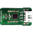
MPU6050 Accelerometer Gyro Temperature
Nice look forward to this and other addons , like Neopixel, an LCD display, an OLED display and also a Infrared transmitter (change channels and triangulate position) and maybe a laser pointer for entertaining the cat.
Used this discussion for instructions for connecting it: https://synthiam.com/Question/Laser-Pointer-7542
Bought 10 for $5 from Amazon. https://smile.amazon.com/GeeBat-10pcs-Laser-Module-Lasers/dp/B01ITK4PEO
I would send you one for free since I have 8 extras (gave one away already), but the mailing cost from US to Canada is more than you would spend getting 10 from Amazon.
Alan
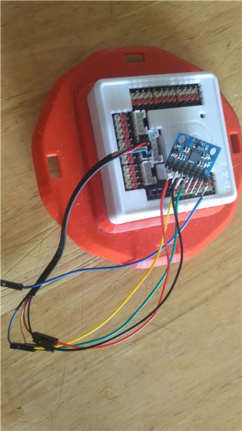
It should, but one thing you should note is that the MPU6050 needs pretty strong pull-up resistors on the SDA and SCL lines to communicate at any kind of distance. In the past I've had to replace the on-board 4.7kohm surface mount resistors with 330ohm ones.
Thanks For the info Jer. I will test it out.
Jeremie, Does EZ Robot still sell these I don't see them on your website? Also can you use a standard MPU6050 board?
"It should, but one thing you should note is that the MPU6050 needs pretty strong pull-up resistors on the SDA and SCL lines to communicate at any kind of distance." What is any kind of distance? Where would you add the the resistors on the standard MPU6050?