
Use DC Motor As Servo
A servo is a type of device used in the world of electronics and robotics for precise control of motion. It consists of a motor (typically a DC or AC motor), a control circuit, and a feedback system, usually a potentiometer. The key feature of a servo is its ability to control its output shaft's position accurately. This is achieved by sending a specific signal to the servo, which moves the shaft to a corresponding angle. Servos are commonly used in applications like radio-controlled models, robotics, and precision mechanical systems because they provide controlled movement and positioning.
While this tutorial demonstrates one solution, you may also consider other options such as using products specifically designed for this. Such as the Dimension Engineering Sabertooth.
Why Would You Need a DC Motor as a Servo?
Using a DC motor as a servo hinges on harnessing its power and controllability. DC motors are appreciated for their simple design, high efficiency, robust performance, and ability to produce high torque at low speeds. However, unlike standard servos, they lack precise control of position. By integrating a DC motor with a control system similar to a servo, which includes feedback mechanisms and an H-bridge for direction control, it becomes possible to use the "infinitely powerful" nature of the DC motor with the precision and accuracy of a servo.
This combination is particularly beneficial in applications requiring high power and precise control. For instance, in industrial robotics or heavy-duty mechanical systems, where the torque and speed of a DC motor are necessary, but so is the precise positioning capability of a servo, this hybrid approach offers the best of both worlds. It allows for creating a powerful and precise system, expanding the possibilities in engineering and robotics.
Objective
To transform a standard DC motor into a precision-controlled device akin to a servo. This is achieved by repurposing the PCB from an existing servo and integrating it with an H-Bridge, which controls the motor's direction and speed.
Key Points and Connection Details
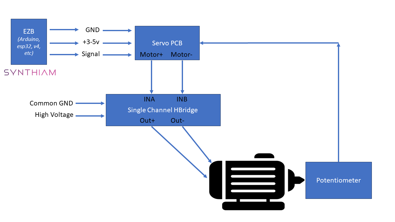
- The servo PCB is powered by +3V or +5V and is aligned with the logic input levels of the H-Bridge.
- Components (PCB and potentiometer) are salvaged from an existing servo.
- The DC motor receives its power independently, allowing it to operate at its full capacity within the limits of both the motor and the H-Bridge.
- The motor wires from the servo PCB are connected to the INA and INB inputs of the H-Bridge, allowing the servo PCB to control the H-Bridge and, in turn, the motor directly.
Components Required
- DC Motor
- Repurposed Servo PCB
- H-Bridge Circuit
- Salvaged Potentiometer
- Separate Power Supplies (Servo PCB can be powered by +3 or +5 from the microcontroller, HBridge motor can be powered directly from the battery)
- Connecting Wires and Accessories
Process Overview
- Extracting Servo Components: Dismantle an existing servo to obtain the PCB and potentiometer.
- H-Bridge Setup: Connect the DC motor to the H-Bridge.
- Servo PCB to H-Bridge Connection:
- Identify the motor output wires on the servo PCB (typically two wires used to control the original servo motor).
- Connect these wires to the INA and INB inputs of the H-Bridge. This setup allows the servo PCB to send directional control signals (forward or reverse) to the H-Bridge, which controls the DC motor.
- Integrating the Potentiometer: Attach the potentiometer to the DC motor for position feedback.
- Powering the System: Use a +3V or +5V supply for the Servo PCB and a suitable separate supply for the motor and H-Bridge.
Applications and Advantages
This approach is beneficial for projects needing the power of a DC motor with servo-like precision control. The method is cost-effective, resource-efficient, and allows for high customization. By utilizing separate power sources for the control circuit and the motor, the setup ensures operational safety and maximizes the motor's performance potential.
Troubleshooting
If the motor is spinning in the opposite direction, reverse the INA and INB wires between the Servo PCB and HBridge