
Create servo frames and actions to animate gaits and gestures with automatic motion planning, software ramping, movement panel, import/export
How to add the Auto Position (Gait) robot skill
- Load the most recent release of ARC (Get ARC).
- Press the Project tab from the top menu bar in ARC.
- Press Add Robot Skill from the button ribbon bar in ARC.
- Choose the Servo category tab.
- Press the Auto Position (Gait) icon to add the robot skill to your project.
Don't have a robot yet?
Follow the Getting Started Guide to build a robot and use the Auto Position (Gait) robot skill.
How to use the Auto Position (Gait) robot skill
If your robot uses servos (humanoids, hexapods, arms, creatures, etc.), you can think of Auto Position as an easy animation system: you pose the robot, save that pose, then build a sequence of poses that plays smoothly.
In robotics, a gait is a repeating movement pattern used for locomotion (walking/crawling). Different robot designs use different gaits: a humanoid often uses a biped walk, while a hexapod uses a multi-leg crawl. Auto Position helps you build those patterns without manually coding every tiny servo move.
Two Versions (Which One Should I Use?)
There are two versions of this skill:
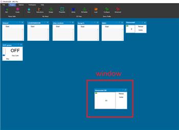
- Auto Position (Movement Panel): Includes on-screen direction buttons (Forward/Reverse/Left/Right/Stop) and integrates with ARC’s movement system. Only one Movement Panel can exist in a project.
- Auto Position (Non-movement panel): No direction pad—use it for animations, gestures, arms, heads, etc. You can add multiple instances of this version.
Not sure what a movement panel is? Read this overview: What is a Movement Panel in ARC?
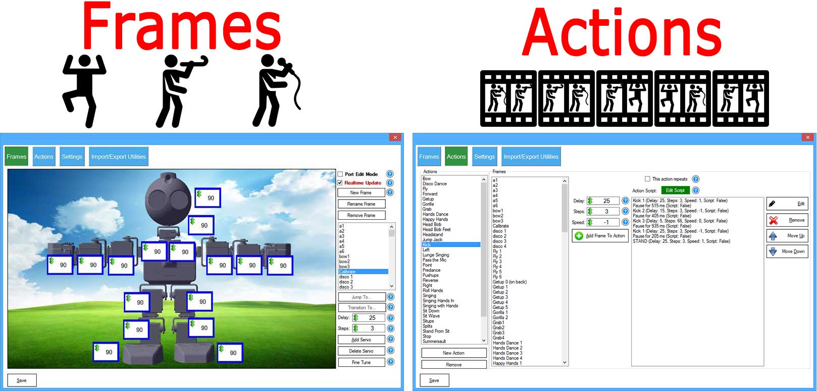
Beginner Concepts: Frames vs Actions
Frame = a single pose (snapshot)
A Frame stores the target position (degrees) for each servo. Example frames for an arm might be: Start, Reach, Grab, Lift.
Action = a sequence of frames (animation)
An Action is an ordered list of frames. When you execute an Action, ARC transitions through those frames one-by-one, creating a smooth motion.
Think of a flipbook: each page is a pose (Frame). Flipping pages in order is the animation (Action).
The smoothness comes from ARC automatically calculating how to transition between servo positions. This is commonly called motion planning and is related to inverse kinematics concepts. If you want the science details, see: Inverse kinematics.
Quick Start (Beginner Workflow)
- Add the skill in ARC: Project → Add Skill → choose the Auto Position version you need.
- Create Frames (poses): Open Configuration → Frames and set servo degrees for each pose you want.
- Create an Action: Open Configuration → Actions, add your frames to the sequence in the order you want them played.
- Tune the movement using Steps and Delay (and optional ramping).
- Run it: Use the main window Execute button (or a script/ControlCommand) to play an action.
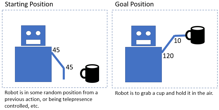
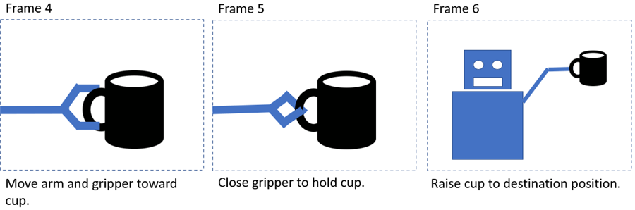
Example: Picking Up a Cup (Action made of Frames)
Imagine a simple robot arm with two joints (shoulder + elbow) and a gripper. “Pick up cup” is one complete Action, but it’s easier to build it as multiple Frames: start position, approach, close gripper, lift, and so on.
1) Create the Frames
Frames are snapshots of servo angles. You don’t need to program each servo movement manually—just define the important poses.
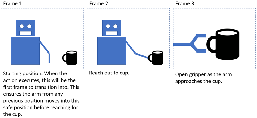
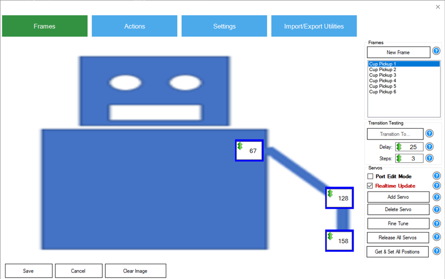
After creating frames, you’ll see a list of frames and their servo positions:
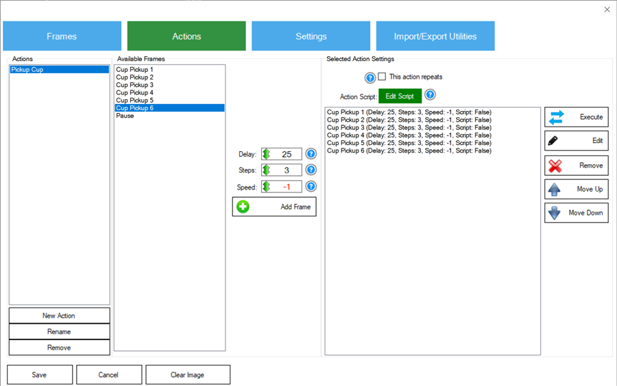
2) Add Frames to an Action
An action is a list of frames plus transition settings (how fast it moves, how smooth it is, and optional scripts).
Understanding Steps & Delay (Speed and Smoothness)
When moving from one frame to the next, Auto Position doesn’t “teleport” servos to the new angles (unless you use Jump To). Instead, it calculates intermediate points so all servos arrive at the next pose at the same time.
Steps (how big each increment is)
- Smaller Steps = more increments = smoother motion (usually slower)
- Larger Steps = fewer increments = faster motion (can look choppier)
Delay (pause between increments)
- Lower Delay (ms) = commands sent faster = quicker motion
- Higher Delay (ms) = commands sent slower = slower motion
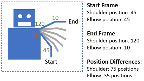
Example: Steps = 5, Delay = 20
Auto Position examines the biggest angle change among all servos in that transition. If the largest change is 75 degrees and steps are 5,
then 75 ÷ 5 = 15 increments are needed. ARC sends those increments with a 20ms delay between them.
Servos with smaller angle changes automatically use smaller per-increment changes so that all servos finish together.
Software Acceleration (Ramping) for Smoother Motion
Some smart servos/controllers (ex: Dynamixel) can do smooth acceleration in hardware. Many basic hobby servos/controllers cannot. When hardware acceleration is not available, Auto Position can simulate smooth movement using software ramping.
How to configure ramping (simple approach)
- Set Steps to the fastest maximum step you want to use during the middle of the move (example:
10). - Set SW Ramping to any value above
0(example:1000).
What ramping does
- Starts with smaller steps (soft start)
- Uses your full Steps value around the middle (normal speed)
- Ends with smaller steps (soft stop)
Note: If SW Ramping is
0, no software ramping is used.
Tutorial Video: Creating a Hexapod Gait
This video shows Auto Position used to create a walking gait for a large 3D-printed hexapod, plus how it can be controlled with other ARC skills.
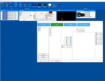
Main Window (What the Buttons Do)
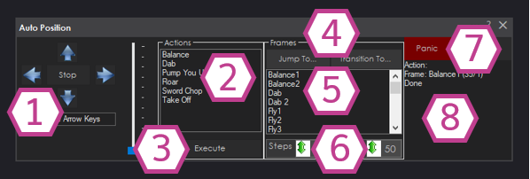
Direction controls for the whole robot (Forward/Reverse/Left/Right/Stop). Keyboard arrow keys can also control movement when the textbox has focus. (Only present in the Movement Panel version.)
Shows all actions you created. Select one before pressing Execute.
Runs the selected action.
Jump To instantly sets the servos to a selected frame (no smooth movement).
Transition To moves smoothly to a selected frame using the current Step/Delay values.
Use these for testing a single frame without running a full action.
A list of frames you can test individually with Jump To or Transition To.
Used by “Transition To” (testing a frame). Smaller delay = faster; smaller steps = smoother (often slower).
Stops Auto Position and releases all servos (helpful if something is moving incorrectly).
Shows what Auto Position is currently doing.
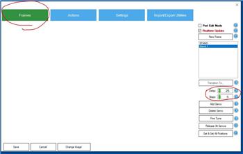
Configuration → Frames (Building Your Poses)
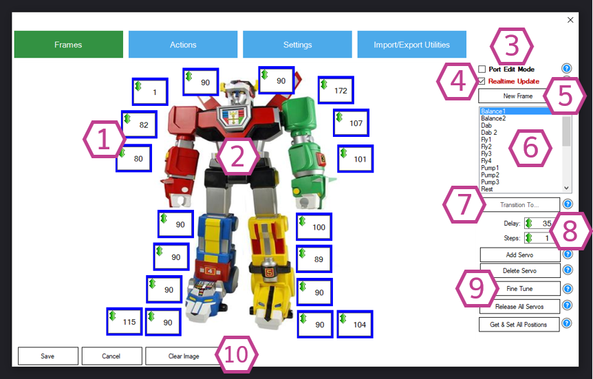
A frame stores a servo position for each servo (in degrees). When Realtime Update is enabled, changing a value moves the robot immediately.
How to edit a servo position (two methods)
- Click and drag the degree value up/down
- Right-click the degree value and type a number
Important servo frame value notes
- servo values 1–180: standard servo degree positions
- servo value 0: releases the servo (or stops a continuous rotation servo)
- servo value -1: skip this servo for this frame (keeps its current position)
Key controls explained
- 1. Servo Positions: each number is a target angle for a specific servo/port
- 2. Background Image: optional picture of your robot to help organize servos
- 3. Port Edit Mode: shows ports and lets you reassign them
- 4. Realtime Update: apply changes immediately (turn off for safe editing)
- 5. New Frame: duplicates a frame so you can make a small change and save it as the next pose
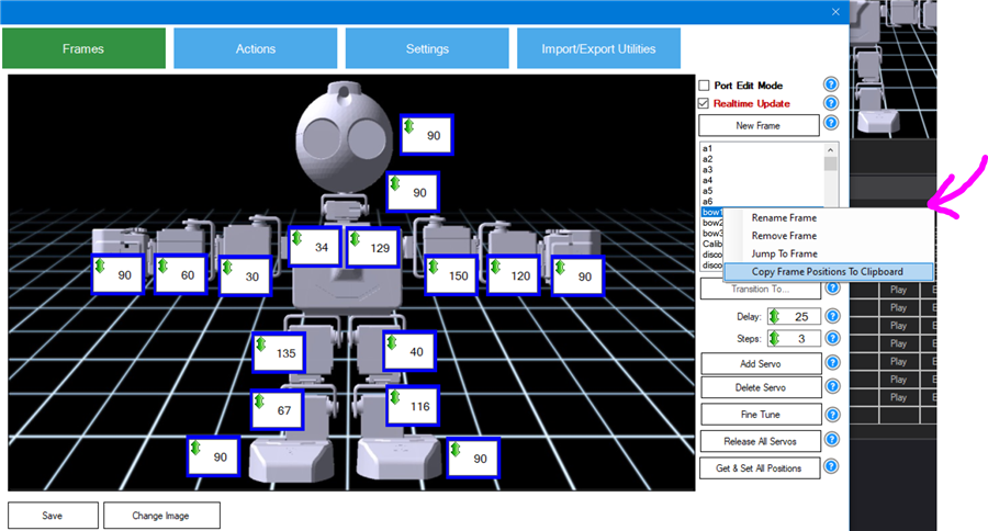
- 6. Frame List: right-click a frame to copy positions to clipboard (useful for scripts)
- 7. Transition To…: test moving into a frame smoothly
- 8. Delay/Step: used for frame testing only (not saved in the frame)
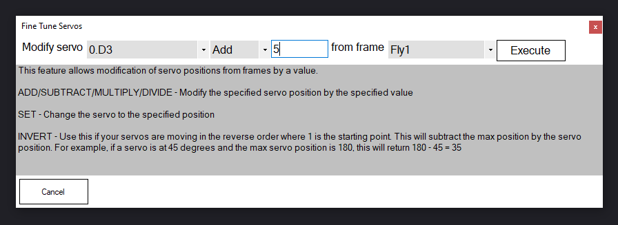
- 9. Servo Management: add/delete servos, fine-tune values, release all
- 10. Clear/Change Image: set/remove the background image
Configuration → Actions (Building Your Animations)
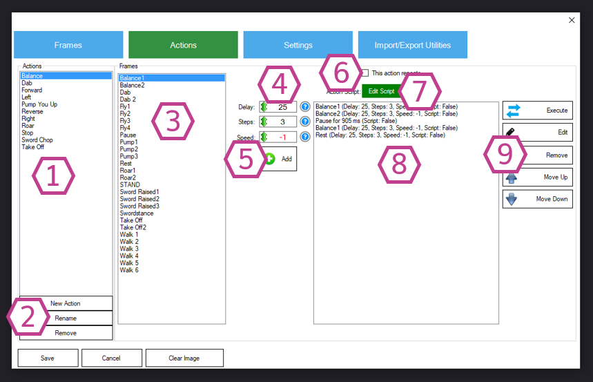
Actions are where you turn frames into an animation or gait. You select a frame, choose how to transition into it, and add it to the sequence list.
All actions you have created (example: Walk Forward, Turn Left, Wave, Dance).
Add, rename, or remove actions.
Pick a frame to add into the action sequence.
These values control how the robot transitions from the previous frame to this frame when the action runs. Some advanced servos support velocity/acceleration in hardware; basic servos may ignore those fields.
Adds the selected frame (with the selected transition settings) to the sequence list.
Loops the action until another action is executed (common for walking gaits).
Add a script that runs when the action executes (for sounds, LEDs, speech, sensor checks, etc.).
The exact order of frames (top to bottom) that will play when the action runs.
Execute/test, edit a step, remove a step, or move steps up/down to reorder the motion.
Configuration → Settings (Scripts and Variables)
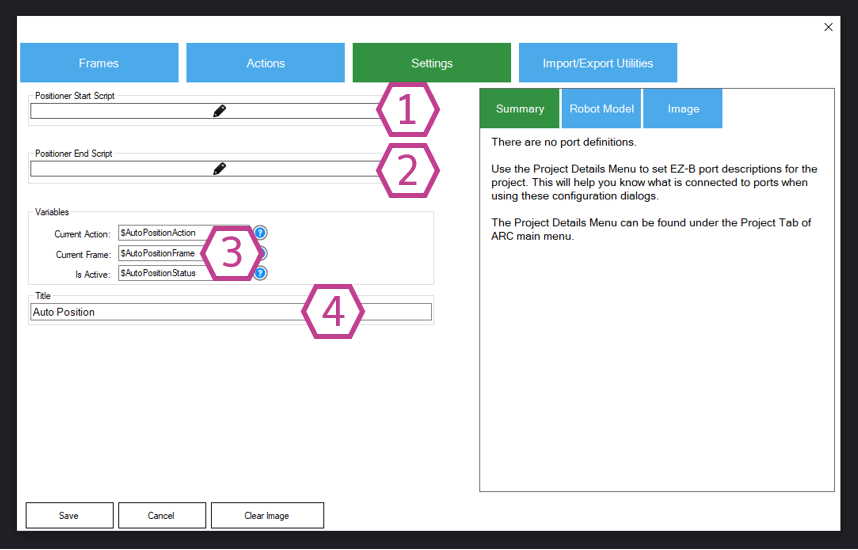
Runs before a frame or action is executed.
Runs after the queue finishes executing.
Includes variables such as the current action/frame and running status (example:
$AutoPositionStatus is 1 when running, 0 when idle).
Renames this skill instance. Important: if you change the title, update any scripts that reference the old name in
ControlCommand().
Import / Export Utilities (Sharing Motions)
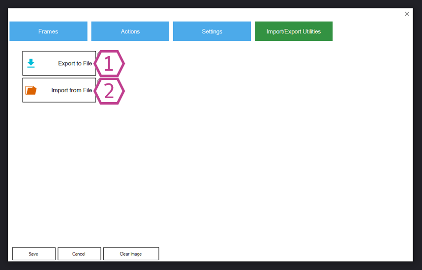
You can export your frames/actions to a file and import them into another ARC project or another Auto Position instance. This is helpful for backups and for sharing gaits.
- 1. Export: saves an
.autopositionfile - 2. Import: loads
.autopositionor.ezbfiles
If ARC warns that a frame already exists, it is often because you attempted to import the auto-generated PAUSE frame. Unselect it during import.
Auto Position With Movement Panel vs Without (Practical Differences)
With Movement Panel
- Includes direction controls and works like ARC movement panels
- Only one movement panel skill allowed per project
- Uses predefined direction actions (Forward/Reverse/Left/Right/Stop)
- Can be driven by movement commands (ex:
Forward(),Stop())
Without Movement Panel
- No directional movement pad
- You can add multiple instances (great for separate body parts)
- Best for gestures/animations (wave, nod, arm sequences, etc.)
- Controlled via
ControlCommand()
Tip: You can export from one version and import into the other as long as the servo configuration matches.
Videos
Resources
Import/export tools are located in the skill’s Configuration menu under the Import/Export tab. Use them to back up your work or move gaits between projects.
Control Commands for the Auto Position (Gait) robot skill
There are Control Commands available for this robot skill which allows the skill to be controlled programmatically from scripts or other robot skills. These commands enable you to automate actions, respond to sensor inputs, and integrate the robot skill with other systems or custom interfaces. If you're new to the concept of Control Commands, we have a comprehensive manual available here that explains how to use them, provides examples to get you started and make the most of this powerful feature.
Control Command ManualAutoPositionStop
Example: controlCommand("Auto Position", "AutoPositionStop")
ShowAutoPositionPose
Example: controlCommand("Auto Position", "ShowAutoPositionPose")
"AutoPositionFrame", "STAND", [delay], [steps], [speed]
Example: controlCommand("Auto Position", "AutoPositionFrame", "STAND", [delay], [steps], [speed])
AutoPositionFrameJump", "STAND
Example: controlCommand("Auto Position", "AutoPositionFrameJump", "STAND")
DeleteActionAndAssociatedFrames", "Action Name
Example: controlCommand("Auto Position", "DeleteActionAndAssociatedFrames", "Action Name")
AddFrameToAction", "Action Name
Example: controlCommand("Auto Position", "AddFrameToAction", "Action Name")
AddFrameToAction", delay, steps, speed, "Action Name
Example: controlCommand("Auto Position", "AddFrameToAction", delay, steps, speed, "Action Name")
AddPauseToAction", delay in ms, "Action Name
Example: controlCommand("Auto Position", "AddPauseToAction", delay in ms, "Action Name")
Related Tutorials
Related Questions
Struggling With Autoposition
Head Calibration Fail
Speed Vs Velocity Configuration

Upgrade to ARC Pro
Harnessing the power of ARC Pro, your robot can be more than just a simple automated machine.
Is there a way to reset the defaults number (4)in your upper picture? I work with steppers and there is a big difference in the positions compared to servos. Steppers start with 1 and servos are the center number between min and max. I have to keep changing the values, it would just make things a bit easier.