
Drive 16 servos over EZB I2C with a PCA9685 PWM controller, using ARC servo commands and hardware-timed outputs.
 Hardware Info
How to add the PCA9685 Servo Driver robot skill
- Load the most recent release of ARC (Get ARC).
- Press the Project tab from the top menu bar in ARC.
- Press Add Robot Skill from the button ribbon bar in ARC.
- Choose the Servo category tab.
- Press the PCA9685 Servo Driver icon to add the robot skill to your project.
Don't have a robot yet?
Follow the Getting Started Guide to build a robot and use the PCA9685 Servo Driver robot skill.
How to use the PCA9685 Servo Driver robot skill
A robot skill that turns any EZB-connected I2C bus into a 16-channel hobby servo controller by driving a low-cost NXP PCA9685 PWM chip.
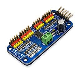
What is the PCA9685?
The PCA9685 is a popular 16-channel, 12-bit PWM controller from NXP. It is controlled entirely over I2C and can generate clean, hardware-timed PWM signals for LEDs, servos, or anything else that expects a pulse-width input. Boards built around this chip (such as the Adafruit 16-channel servo HAT/shield and many lower-cost generic clones available from Amazon and Alibaba) are inexpensive and widely available.
This robot skill acts as a bridge between ARC's servo subsystem and a PCA9685 sitting on your EZB's I2C bus. When ARC commands a servo to move, the skill converts that movement into the correct PWM pulse width and writes it to the PCA9685 over I2C. From ARC's point of view, the PCA9685 channels look like ordinary virtual servo ports - by default V0 through V15, or any other 16-port window (V16..V31, V32..V47, ...) that you select in the configuration.
In simpler terms: Think of this skill as a translator. ARC speaks "servo position" (like 1-180 degrees), while the PCA9685 speaks "PWM signals." This skill converts between the two so you don’t have to worry about low-level electronics.
Why You'd Use It
- More servo channels. The PCA9685 adds 16 servo outputs to any EZB that has an I2C port, without using up the EZB's native digital servo pins. Great for large robots with many moving parts.
- Hardware-timed PWM. The PCA9685 generates pulses in hardware, so servo jitter is low even when the host is busy. Your servos move more smoothly and reliably.
- Wide voltage range. The chip operates from 2.3V to 5.5V on the logic side, and the V+ rail can be powered separately to match your servos. You can safely power stronger servos without stressing your EZB.
- Use existing ARC servo features. Because the skill exposes the channels as
V0..V15, you can drive them from any existing ARC skill that commands servos - Auto Position, Inverse Kinematics, speech gestures, scripts, etc. No need to learn anything new - everything works like normal servo ports. - Chain multiple boards. The PCA9685 has address-select pins, so you can put several boards on the same I2C bus at different addresses. Add one instance of this skill per board and give each instance a different Port Range (e.g. board 1 =
V0..V15, board 2 =V16..V31, board 3 =V32..V47, ...). Scale up to dozens of servos without any port conflicts.
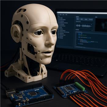
How It Connects to the EZB
The PCA9685 is an I2C device, so you wire it to your EZB's I2C port:
| PCA9685 pin | EZB I2C pin |
|---|---|
| VCC | 3.3V or 5V |
| GND | GND |
| SDA | SDA (data) |
| SCL | SCL (clock) |
Important Notes for Beginners
- I2C is a communication protocol that uses just two wires:
- SDA = data
- SCL = clock
- Servo power is separate! Servo power (the V+ rail on the PCA9685 board) must come from a separate supply sized for your servos - do not try to power servos from the EZB's logic rail.
- Shared ground is required. Always connect the PCA9685 ground to the EZB ground. Without a common ground, signals won’t work correctly.
- Addressing the board:
Most PCA9685 breakout boards have solder-jumper address pads (A0..A5). By default, the 7-bit I2C address is
0x40, which becomes0x80in the 8-bit form that the EZB'sI2C.WriteAPI expects.
How to Use It
- It is important to wire the PCA9685 board to the EZB's I2C port and connect V+ to a suitable servo power supply before any other step. Some EZB firmware or hardware may lock up if trying to communicate with an I2C device that is not present, such as the EZ-Robot EZB v4. Ensure all power is disconnected when connecting peripherals to microcontrollers.
- Plug your servos into channels 0..15 on the PCA9685 board, paying attention to signal/+/- orientation.
- If the wiring has been verified, apply power to both the EZB and the PCA9685 according to your use case.
- Open the skill's configuration (gear/config button in the title bar) and set the I2C address, pulse-width limits, and Port Range to match your hardware - see Configuration below.
- Connect to your EZB. Upon connection, the skill automatically runs the PCA9685 wake-up and prescale sequence. You should see a log line similar to:
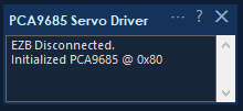
Initialized PCA9685 @ 0x80
- From any other skill, command a servo on any port in the selected Port Range window (by default
V0throughV15).
Channel Mapping
Whichever 16-port window you select in the configuration is mapped onto the PCA9685's 16 physical channels, in order. With the default V0..V15 window:
V0PCA9685 channel 0V1PCA9685 channel 1- ...
V15PCA9685 channel 15
If you select a different window (for example V16..V31 on a second board), the first port in the window maps to channel 0:
V16PCA9685 channel 0V17PCA9685 channel 1- ...
V31PCA9685 channel 15
These behave exactly like normal servo ports in ARC. Ports outside the selected window are ignored by this plugin instance, so multiple PCA9685 boards can share one project without stepping on each other.
How a servo Command Becomes PWM
When ARC commands a move, the skill:
- Takes the ARC servo position (
1..SERVO_MAX). Configure the MAX servo position in the ARC -> Project -> Options menu. - Linearly maps it into the configured pulse-width range (
Min s..Max s). - Clamps the result to stay inside those limits.
- Converts microseconds to a 12-bit tick count inside the PCA9685's 20 ms (50 Hz) frame.
- Writes a single 4-byte I2C transaction to the PCA9685.
Why This Matters
You don’t need to manually calculate PWM signals - the skill handles everything automatically. You just tell ARC:
Servo(V3, 90)
and the hardware does the rest.
Configuration
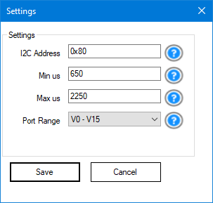
Click the gear/config button in the robot skill's title bar to open the configuration form.
I2C Address
The 8-bit I2C address of the PCA9685 on the EZB's bus.
- Default:
0x80 - Required when using multiple boards
Tip: If your board isn’t responding, this is the first thing to check.
Min s
The pulse width that corresponds to the minimum servo position.
- Default:
650 - Typical range:
500-1000
Lower values = more travel, but too low can damage the servo.
Max s
The pulse width that corresponds to the maximum servo position.
- Default:
2250 - Typical range:
2000-2500
Higher values = more travel, but too high can cause buzzing or strain.
Port Range
Selects which 16-port window of ARC virtual servo ports this plugin instance binds to. The chosen window is mapped onto the PCA9685's physical channels 0..15 in order.
- Default:
V0 - V15 - Options:
V0 - V15,V16 - V31,V32 - V47, ... (the list is populated from the Vx ports available in your ARC build, grouped into 16-port windows)
When to change this: only when you have more than one PCA9685 board in the same project. Give each board a unique I2C address and a unique port range so their ARC virtual ports don't overlap. For a single-board setup, leave this on the default V0 - V15.
Example - three PCA9685 boards driving 48 servos:
| Plugin instance | I2C Address | Port Range |
|---|---|---|
| Board 1 | 0x80 |
V0 - V15 |
| Board 2 | 0x82 |
V16 - V31 |
| Board 3 | 0x84 |
V32 - V47 |
Any ARC skill (Auto Position, Inverse Kinematics, scripts, etc.) can then command V0..V47 and the correct board will respond.
Beginner Tip
If you’re unsure:
- Start with defaults
- Slowly adjust while watching the servo
- Stop if you hear buzzing or see resistance
Troubleshooting
PCA9685 init failed @ 0x80Check wiring and address- EZ-Robot EZB V4.x locks up (solid red LED) Likely I2C wiring issue Fix wiring, then power cycle EZB
- Servos jitter Almost always a power issue Use a stronger external power supply
- Servo hits hard stop Adjust Min/Max s range
- Nothing happens on V0-V15
Confirm initialization message appears
Confirm the Port Range in the configuration matches the ports you are commanding (e.g. if the range is
V16 - V31, commandingV0will do nothing on this board) - Random movement on startup Normal behavior during initialization
Limits and Notes
- Fixed at 50 Hz (standard for servos)
- Only supports 16 channels per board
- Each plugin instance binds to one configurable 16-port Vx window (default
V0..V15); add more instances with different port ranges to drive additional boards - Does not "release" servos - it continuously sends position signals
Final Notes for New Users
If this is your first time using I2C or external servo drivers:
Related Questions
Inmoov Head Movements

PCA9685 I2C Port Selection

Upgrade to ARC Pro
Become a Synthiam ARC Pro subscriber to unleash the power of easy and powerful robot programming