

Ultrasonic on a servo sweeps 180°; radar shows distances and obstacles, integrates with movement panels for automatic avoidance, scriptable GetPing
 Hardware Info
How to add the Ultrasonic Radar robot skill
- Load the most recent release of ARC (Get ARC).
- Press the Project tab from the top menu bar in ARC.
- Press Add Robot Skill from the button ribbon bar in ARC.
- Choose the Ultrasonic category tab.
- Press the Ultrasonic Radar icon to add the robot skill to your project.
Don't have a robot yet?
Follow the Getting Started Guide to build a robot and use the Ultrasonic Radar robot skill.
How to use the Ultrasonic Radar robot skill
Beginner Overview
This robot skill is designed for simple obstacle detection and avoidance. It combines:
- Ultrasonic distance sensor (example: HC-SR04) to measure how far away an object is
- Servo to rotate the sensor so it can “look” in different directions
- Radar display to visualize where objects are detected
- Movement Panel integration (optional) to automatically steer away from obstacles
How Ultrasonic Sensors Work (Simple Explanation)
Ultrasonic sensors use sonar—they send out a high-frequency sound “ping” and measure how long it takes for the echo to return. This is similar to how bats and dolphins sense their surroundings.
- Good at: hard surfaces (walls, furniture, boxes)
- Not as good at: soft or angled surfaces (fabric, curtains, cushions) because the sound can be absorbed or bounce away
- Compared to infrared (IR): ultrasonic is usually less affected by sunlight and dark/black surfaces
What You Need Before You Start
- An EZB connected to ARC
- An ultrasonic sensor (HC-SR04 or equivalent, or EZ-Robot ultrasonic)
- A servo (to sweep the sensor)
- A way to mount the sensor to the servo (bracket, hot glue, 3D print, etc.)
- (Optional) A Movement Panel skill in your ARC project if you want automatic avoidance
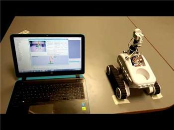
When the sensor is connected and configured, the skill will show the distance straight ahead of the sensor. When the servo sweeps, the radar display updates to show obstacles across the scan range.
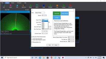
Main Window
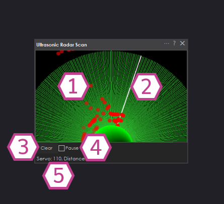
1) Radar Display
Shows detected objects as red dots in front of the robot (up to about 180° depending on your servo settings). The displayed distance values range from 0–255, representing the sensor’s reported reading.
Tip: If you see dots “stuck” on the screen from older scans, use Clear.
2) Sweep Line
The sweep line indicates where the servo is currently pointing. As the servo moves, this line rotates across the radar.
3) Clear Button
Clears the red dots from the radar display. This does not change settings; it only clears what you see on the screen.
4) Pause Checkbox
When checked, the skill stops sampling the ultrasonic sensor and stops moving the sweep servo. This is useful for testing, saving CPU/communication, or letting scripts control updates (see scripting section below).
5) Servo and Distance Values
Displays the current servo position value being sent and the most recent ultrasonic distance reading. Use this area to confirm the servo is moving and the sensor is returning readings.
Settings
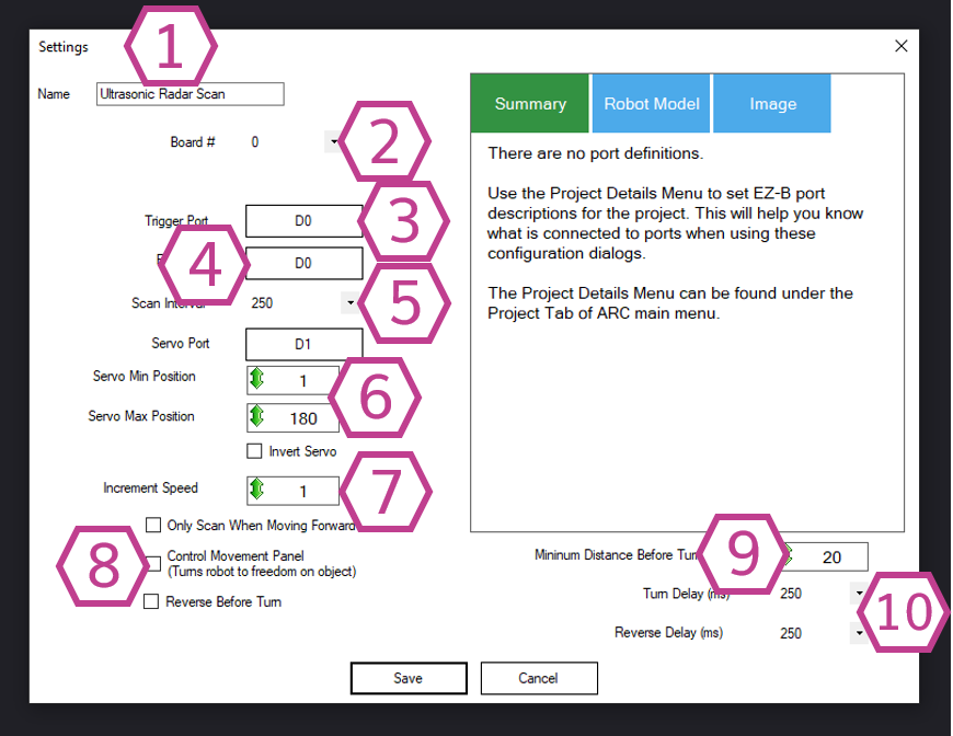
1) Title Field
Sets the name of this skill in your ARC project.
Important: If you use controlCommand() in scripts, changing the title also changes the name you must reference.
2) Board Index
Choose which EZB this sensor is connected to (for example, Board 0 is the first EZB in most projects).
3) Trigger Port
Select the digital port used by the Trigger (sometimes labeled “TRIG”) wire.
4) Echo Port
Select the digital port used by the Echo (sometimes labeled “ECHO”) wire.
5) Interval (ms)
How often the sensor is sampled, in milliseconds (100–60000 ms). Default is 250 ms. Smaller values update faster but use more communication/resources.
6) Servo Settings (Sweep Setup)
Choose the servo port and set the minimum and maximum positions for the sweep. These min/max values define how far left and right the sensor turns.
- Min/Max positions: limit the sweep to prevent hitting the robot frame
- Invert servo: reverses the sweep direction if movement looks backwards
7) Increment Speed
Controls how quickly the servo steps through the sweep (1–36, default 1). Increase this if you want the sweep to move faster.
8) Movement Options (Checkboxes)
These options let Ultrasonic Radar interact with your project’s Movement Panel skill for obstacle avoidance.
- Scan only when moving forward: only scans when the robot is driving forward (reduces unnecessary scanning)
- Control Movement Panel: allows the skill to command turns/reverses automatically
- Reverse before turning: backs up first, then turns away from the obstacle
9) Minimum Distance Before Turn
Sets the threshold (value 1–255, default 20) that triggers avoidance. If the reading is at/under this limit, the skill will command the Movement Panel to turn (when Movement options are enabled).
10) Movement Delay (Turn / Reverse)
How long the robot should reverse and/or turn, in milliseconds (10–5000 ms, default 250 ms). These apply only when the skill is controlling a Movement Panel.
Distance Values (Important for Beginners)
The distance displayed by this skill is a 0–255 value. It is not automatically labeled as centimeters or inches. The exact value can vary based on sensor type, voltage, the surface material, and temperature.
If you need a real-world unit (cm/in), measure with a tape measure and note what value the sensor reports at known distances, then use that as your reference.
Scripting Integration (Using GetPing)
This skill can be updated from scripts using GetPing() (with the same ports you configured in the skill).
If the Pause checkbox is checked, the skill will not continuously scan—but it will still update when your script calls GetPing().
Wiring Diagram
Ultrasonic sensors commonly come in 3-wire and 4-wire versions, sometimes with a built-in voltage regulator. If your sensor includes a regulator, it typically needs Vin (6V+). If it does not include a regulator, it usually needs 5V.
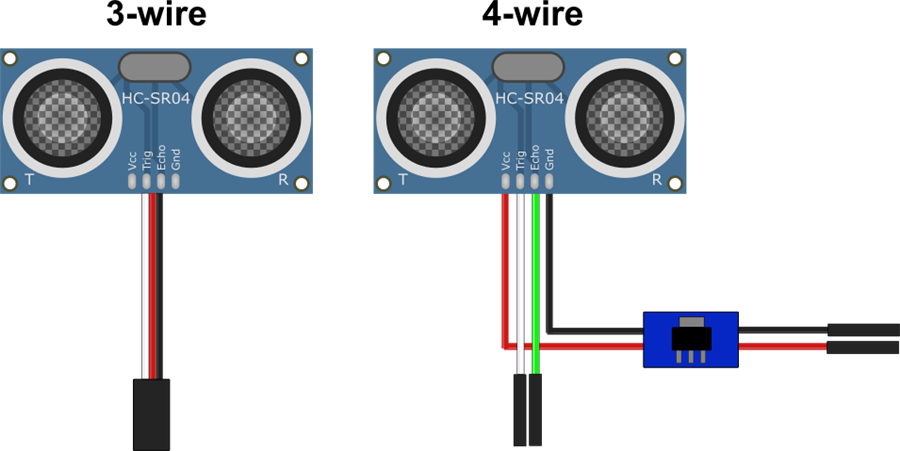
3-wire Wiring (with built-in regulator)
- Ground (Black) → GND
- Power (Red) → Vin
- Trigger/Echo (White) → Digital (D) pin (single shared pin)
4-wire Wiring (with regulator)
- Ground (Black from regulator) → GND
- Power (Red from regulator) → Vin
- Trigger (White) → Digital (D) pin
- Echo (Green) → Second Digital (D) pin
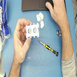
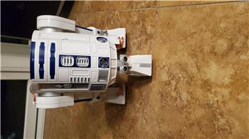
Fix Ultrasonic “False Positives” (EZ-Robot Sensor Tip)
If you are using an EZ-Robot ultrasonic distance sensor and you see occasional false readings, the ping sound may be echoing inside the sensor casing. A simple fix is placing a few cotton balls inside the case around the sensors to dampen internal reflections.
Watch the video below for step-by-step instructions.
Resources
Synthiam provides an ultrasonic hardware reference design here.
Related Tutorials
Related Questions
Experiencing Difficulty With ARC Beta And Web Page Synthiam...
How Do I... Not Be Hopelessly Lost?
Ultrasonic; ADC Or Digital??
Ultrasonic Radar Panel Bot Keeps Doing Circles

Upgrade to ARC Pro
Harnessing the power of ARC Pro, your robot can be more than just a simple automated machine.
Feature Request, would it be possible to also send this skill as an output to the camera, such as in the skill "The Better Navigator"?
send the actual picture ...
Regards Uwe
.
Use this robot skill: https://synthiam.com/Support/Skills/Camera/Screen-To-Camera?id=21222
That's exactly what I was looking for and couldn't find. Perfect, thank you ...
Haha that’s because I just made it when I saw your question
ahh, i was wondering why i didn't see it, but it's new, thank you very much.
You might prefer this robot skill instead, as it captures the robot skill rather than the screen area: https://synthiam.com/Support/Skills/Camera/Robot-Skill-to-Camera?id=21225
Would anyone have any suggestions on how to use this and a Movement Panel if I wanted to use 4 ping sensors, one in each direction?
As I understand it, I would need to turn each ping sensor on and off before using it in order for them not to interfere with each other.
This robot skill uses one ping sensor mounted on a servo. You can scroll up and read the manual, which does a better job than me explaining it.