

EZ-B V4 by EZ-Robot


Firmware
The Synthiam EZ-B v4/2 (often called “EZ-B v4”) is the main controller (the “brain”) for a robot or IoT project. It’s used in thousands of robots worldwide and is designed so beginners can start quickly while still supporting advanced builds. You control the EZ-B from a computer over WiFi using Synthiam ARC (software that sends commands to the board).
Inside the EZ-B v4/2 are dual Cortex ARM processors (220MHz) that handle real-time tasks like servo control, digital inputs/outputs, and audio/video streaming. The board includes built-in WiFi, an embedded web server for configuration, amplified audio output for a speaker, multiple serial buses (I²C and UART), and many ports for servos and sensors.
- Digital ports (D0–D23): plug in servos, LEDs, switches, many sensors, and some serial devices
- Analog ports (A0–A7): read “variable” sensor values (like knobs, light sensors, etc.)
- I²C ports: connect smart sensors/modules that share two data wires
- UART ports: connect serial devices that send/receive bytes (bi-directional serial)
- Camera port: dedicated connector for the EZ-Robot Camera (v2)
- WiFi: connect directly to your computer or join your home network
Datasheet (for specs & safety)
A datasheet is the official document that lists electrical limits and detailed specifications (for example: voltage ranges, current draw, and signal levels). If you are unsure whether something is safe to plug in, the datasheet is the first place to check.
View DatasheetWhere to Buy
EZ-Robot products are available through the official store and select retailers:
Introduction (What you’ll do first)
The EZ-B v4, EZ-Robot Developer Kit, and IoTiny are great for building custom robots or upgrading toys with motors and sensors. If you’re brand new, the best first goal is simple: connect the EZ-B to power, connect to it from ARC, then move one servo.
- Power the EZ-B safely (match battery voltage to what your servos/sensors can handle).
- Connect to EZ-B over WiFi (AP mode first).
- In ARC, add a servo control and move a servo on a digital port (ex: D0).
- Add a camera (optional) and test streaming.
- Expand with sensors (digital, analog, I²C, UART).
EZ-B v4 Port Summary (Where things plug in)
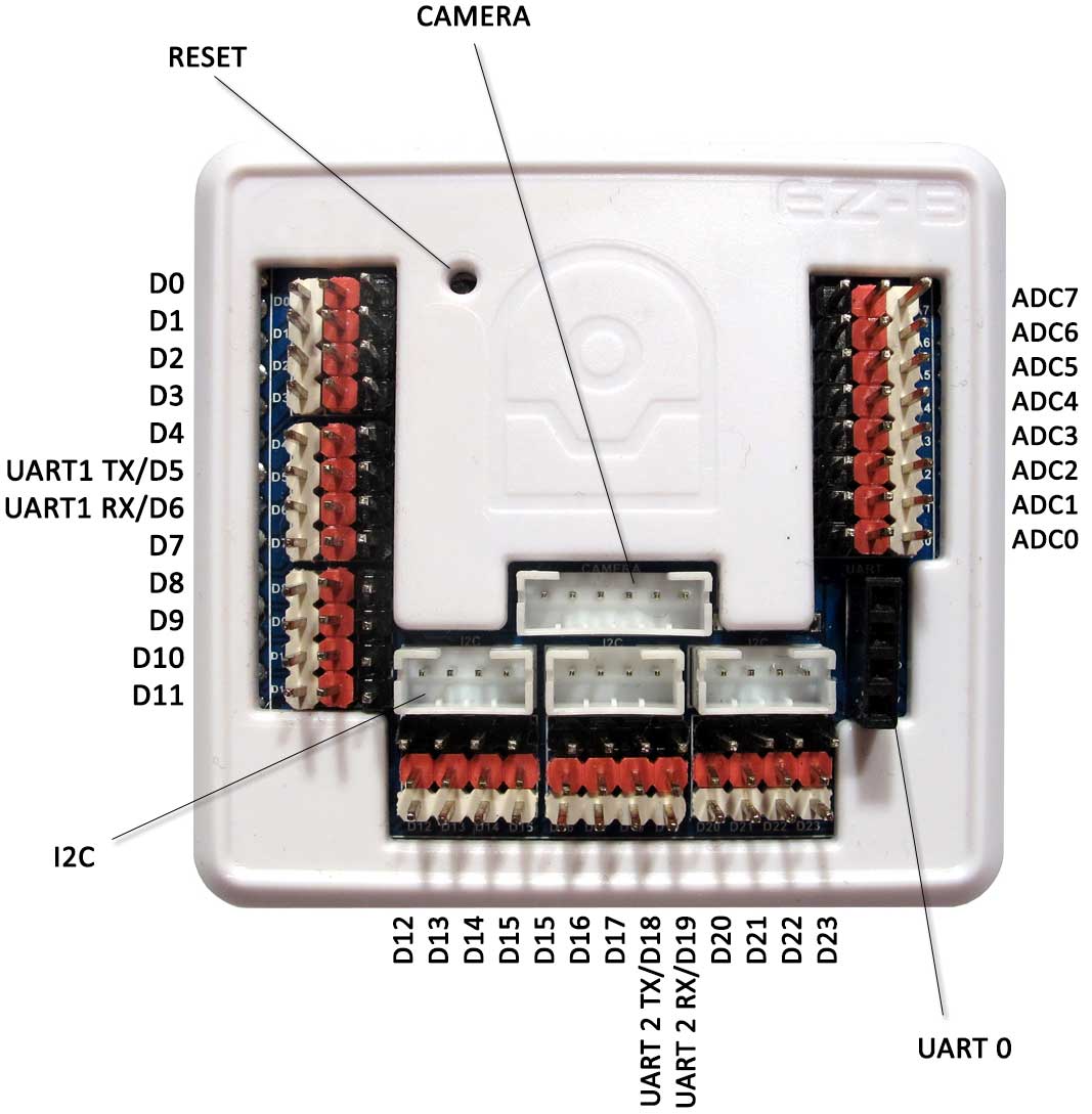
The EZ-B v4 includes: 24 Digital ports (D0–D23), 8 Analog (ADC) ports (A0–A7), 3 UARTs, 3 I²C ports, and a dedicated camera connector. There is also a reset button (press with a small pin) that can restore factory defaults.
3-Pin (GVS) Connectors (What the 3 pins mean)
Most EZ-B ports use a 3-pin layout called GVS: Ground, Voltage (power), and Signal.
Example: A servo has three wires. Ground and Voltage power the servo motor and electronics, while the Signal wire carries the position command (telling the servo what angle to move to).
Connecting a Camera (EZ-Robot Camera v2)
The EZ-Robot Camera connects using a 6-pin cable to the dedicated camera port. The connector is keyed (notched) so it should only fit one way. Don’t force it—if it doesn’t slide in easily, re-check alignment.
- Reseat the cable on both ends (loose connections are the most common issue).
- Check for bent pins or damage near the connector.
- Avoid sharply bending the cable at the plug—repeated flexing can break wires internally.
Connecting Servos & Basic I/O
Many servo/sensor cables are color-coded. On most servos, the black or brown wire is Ground. Align that wire with the black side of the EZ-B port.
- Power the EZ-B with a battery voltage safe for your servo(s).
- Plug the servo into a digital port (example: D0) with correct orientation.
- In ARC, add a servo control and select port D0.
- Move the slider slowly at first to confirm smooth movement.
Connecting Over WiFi (AP Mode vs Client Mode)
The EZ-B v4 can connect over WiFi in two ways:
The EZ-B creates its own WiFi network. Your computer connects directly to the EZ-B’s WiFi. This is the default mode after factory reset.
The EZ-B joins your home/office WiFi. This can be more convenient, but requires correct WiFi credentials and you’ll need to find the EZ-B’s IP address on your network.
Switching between modes is done in the EZ-B’s web configuration page. To restore factory defaults, press the reset button while the device is powered on.
- No internet while connected in AP Mode: that’s normal; you’re connected directly to the robot.
- Can’t see the EZ-B WiFi network: confirm the EZ-B is powered and has finished booting, then reset to defaults.
- Connection drops when servos move: often a power issue (battery sag). Use a battery that can supply enough current.
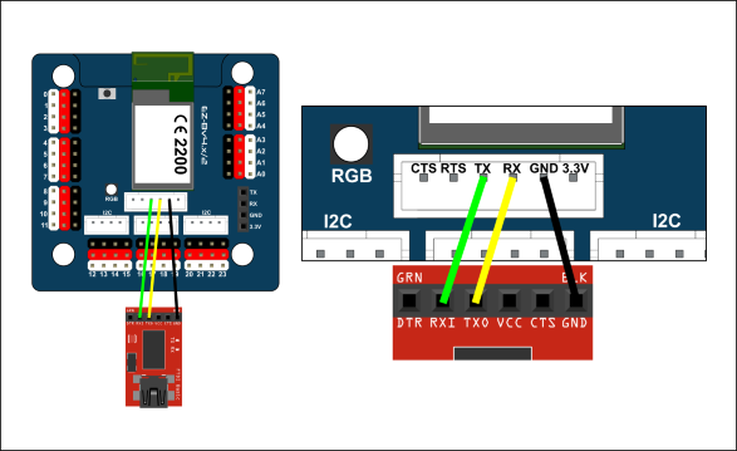
Connecting Over Serial/USB (Optional Alternative to WiFi)
You can connect a PC directly to the EZ-B v4.x/2 using a USB-to-Serial/UART cable. This bypasses WiFi and can help in environments with wireless interference or when you want the lowest latency.
Full instructions: Serial/USB Connectivity Instructions
EZ-B v4 Ports Overview (Video)
EZ-B v4 Rollout Video (Deep Dive)
This detailed video explains the EZ-B v4 design, including E-01 EZ-B v4 Main Board and E-15 EZ-B v4 WiFi Board reference designs.
Power: Read This Before Plugging In Anything
Power is the #1 place beginners run into problems. The EZ-B can run from several battery types and voltages, but your servos and sensors may not. Always verify what voltage your peripherals expect.
- Servos draw a lot of current. If the robot resets when moving, your battery may be too weak.
- Use proper fusing/protection when building larger robots.
- Start small: test one servo first, then add more.
Power Monitor (Low Battery Protection)
EZ-B products include a battery monitor to help warn about low battery conditions (especially important with LiPo batteries). You can disable the battery monitor in two places: the ARC connection skill settings and the EZ-B web configuration.
Web Configuration (Built-in Setup Page)
The EZ-B includes a built-in web server for advanced settings (WiFi mode, security, and other options). With factory-default settings, connect your computer to the EZ-B WiFi network, then open: https://192.168.1.1
- Confirm you are connected to the EZ-B WiFi (AP mode) and not your home router.
- Try a different browser.
- Power-cycle the EZ-B and try again.
UART Serial (Bi-directional Serial Devices)
UART ports are used to communicate with TTL serial devices (for example: some sensor modules, motor controllers, GPS units, or other microcontrollers). “Bi-directional” means the device can both receive commands from the EZ-B and send data back.
UARTInit(), UARTWrite(), UARTRead(), and UARTAvailable().
Each UART includes a 5,000-byte input buffer. Speeds can be set from 1 to 3,750,000 bps.
- EZ-B TX → Device RX
- EZ-B RX → Device TX
- EZ-B GND ↔ Device GND (common ground)
| Electrical Characteristics (Definitions) | |
|---|---|
| Term | What it means (plain language) |
| Vin | The main input power voltage from your battery/DC supply (slightly reduced by the input diode drop, which varies with current). |
| Vcc | The board’s regulated internal supply (3.3V) produced by the on-board switching regulator. |
| Digital I/O | Pins used for ON/OFF type signals (inputs read HIGH/LOW, outputs set HIGH/LOW). |
| ADC | Analog-to-digital converter: reads a voltage (like 0V to 3.3V) and converts it to a number ARC can use. |
| I2C | A two-wire communication bus (SDA/SCL) that allows multiple smart devices to share the same bus. |
| Camera | EZ-Robot Camera (v2) connection. |
| Parameter | Min | Typ | Max | Unit | Note |
|---|---|---|---|---|---|
| Voltage input (Vin) | 4.5 | 7.4 | 16 | VDC | Typ = 2 cell (2S) LiPo |
| Regulated voltage supply (Vcc) | 3.2 | 3.3 | 3.4 | VDC | |
| Vin Continuous Current Draw | 0.008 | 1.3 | 5 | A | Typ = 8 servos |
| Vin Current Spikes (when fuse protected) | 0 | 5 | 20 | A | Typ = 8 servos |
| Vcc Continuous Current Draw | 0 | 0.18 | 1 | A | Typ = EZ-B v4 + camera |
| Vcc Current Spikes | 0 | 0.4 | 3 | A | Typ = EZ-B v4 + camera |
| Vin Default Low Battery Warning OFF | 7 | 16 | VDC | Default 7V for 2S LiPo | |
| Current Draw with No Peripherals | 70 | 80 | 90 | mA | At 7.4V (connected) |
| Current Draw with Camera | 140 | 150 | 160 | mA | At 7.4V (enabled) |
| Digital I/O TTL Voltage Level (input high) | 1.6 | 3.3 | 5 | VDC | 5V Tolerant, High sig > 1.6V |
| Digital I/O TTL Voltage Level (input low) | 0 | 0 | 1 | VDC | Low sig < 1V |
| Digital I/O TTL Voltage Level (output) | 0 | 3.3 | 3.3 | VDC | Regulated to Vcc |
| Digital I/O Power Pin Voltage (output) | 0 | 7.4 | 16 | VDC | Unregulated (follows Vin) |
| ADC Voltage level (input) | 0 | 3.3 | 3.6 | VDC | 5V tolerant |
| ADC Power Pin Voltage (output) | 3.2 | 3.3 | 3.4 | VDC | Regulated to Vcc |
| I2C TTL Voltage Level (input/output) | 0 | 3.3 | 5 | VDC | 5V Tolerant |
| I2C Power Pin Voltage | 3.2 | 3.3 | 3.4 | VDC | Regulated to Vcc |
| Camera Voltage Level (input/output) | 0 | 3.3 | 5 | VDC | 5V Tolerant |
| Camera Power Pin Voltage | 3.2 | 3.3 | 3.4 | VDC | Regulated to Vcc |
Diagnosing a Damaged EZB v4
The EZB v4 uses two main circuit boards that work together during startup. The top board contains the communication processor and Wi-Fi antenna. The bottom board contains the I/O processor, which is responsible for handling hardware functions such as port control and startup audio.
When the EZB v4 powers on, the communication processor initializes first and then sends startup commands to the I/O processor. Once the I/O processor responds correctly, the EZB can complete its startup sequence, including playing the startup sound.
What It Means When the Startup Sound Does Not Play
If the startup sound does not play, the speaker may appear to be the problem, but that is usually not the cause. In many cases, the missing sound is a symptom that the lower I/O processor is not responding properly.
During connection, the communication processor accepts the incoming connection and performs the initial EZB protocol handshake. After that, it passes control to the I/O processor, which must return its firmware ID. This firmware ID is stored internally in the I/O processor and is required for the connection sequence to continue.
If the connection log stops at the firmware ID request and no firmware ID is returned, that indicates the I/O processor is not responding. This is a strong sign that the bottom board has been damaged.
Why the Camera May Still Work
In some cases, the camera may still function even when the EZB cannot complete a full connection. This is because the communication processor on the top board handles the camera video stream. A working camera does not confirm that the entire EZB is healthy. It only confirms that the communication board is still operating.
Common Cause of This Failure
The most common cause of this type of failure is electrical damage to the I/O system. This can happen if I/O pins are shorted, overloaded, or exposed to excessive voltage or current. Although the EZB v4 includes protection on its I/O circuitry, that protection has limits and cannot prevent all damage under severe conditions.
In these cases, the communication board may continue working while the lower I/O board becomes permanently damaged. This results in symptoms such as missing startup audio, incomplete connection attempts, and failure to return the firmware ID during initialization.

wil there be a connection for a speaker in the future?similar like the iotiny.:D
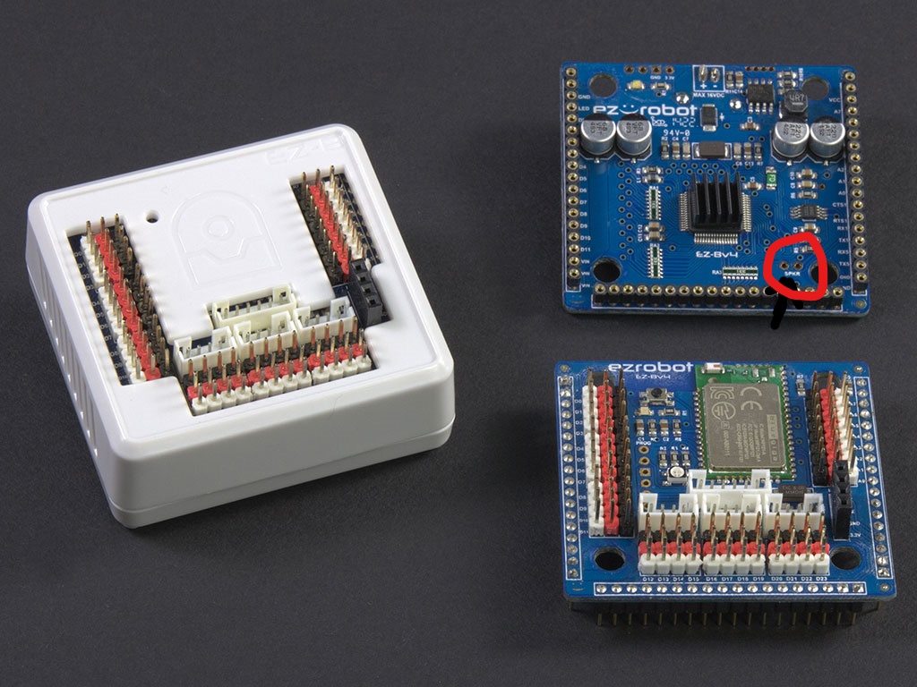
Nomad, What I did was, on the Bottom Board I soldered wires on the pads marked speaker. Then connect that to a speaker or if you need it louder to a small amplifier. See the picture for the locationhi rz90208
i know this .but that wasn my question.thanks you for your rspond do.
happy new year
Sorry to post when the answer is somewhere, but with the split between the two websites I have difficulty finding some stuff. Can someone point me to the write up on adding a SSID to the EZBs? ALAN and ALENA are set up with the direct connection to the computer, but I still see the EZBs wifi broadcasting on my networks. I would like to lock them up with a SSID so at CES no one can connect to them...thanks in advance.
The eZrobot products have their own tutorials on the ezrobot website. This is not support for ezrobot products.
It’s not a split between websites. Ezrobot has products and their products are supported on that website. Use the website for the manufacturer, which is ezrobot.
Visit the ezrobot website and view the learn section to learn how to use the ezrobot products.
Or, you know, you could just post the link.... https://synthiam.com/Community/Tutorials/116?courseId=4
Then I am lost as ever as to what Synthiam is all about. So to clarify, Synthiam is software only? Has ARC been rebranded Synthiam? All the questions here are only software related? All hardware "products" belonging to EZ Robot are "their" domain to support? Along with the EZ Robots website that will support how the hardware works/videos and manuals?
@Alan, thank you found it and got the SSID figured out.
Not A question but some info Hobbyking has [color=#000000][size=3][font=Roboto, sans-serif]EZ-B V4 WIFI ROBOT CONTROLLER $49.99 tthis is great price for a fantastic piece of equiptment.