
 Hardware Info
How to add the Ultrasonic Distance robot skill
- Load the most recent release of ARC (Get ARC).
- Press the Project tab from the top menu bar in ARC.
- Press Add Robot Skill from the button ribbon bar in ARC.
- Choose the Ultrasonic Distance category tab.
- Press the Ultrasonic Distance icon to add the robot skill to your project.
Don't have a robot yet?
Follow the Getting Started Guide to build a robot and use the Ultrasonic Distance robot skill.
How to use the Ultrasonic Distance robot skill
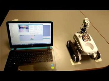
Ultrasonic sensors use sonar (sound navigation ranging) to determine the distance to an object or wall, the same way some animals like bats and dolphins do. They offer excellent range and accuracy in an easy-to-use package. Unlike infrared sensors, their operation is not affected by sunlight or black materials. However, they have trouble with soft fabrics; the sonar echo works ideally when bouncing off hard surfaces.When an HC-SR04 or equivalent Ultrasonic Distance Sensor is connected to an EZB, this skill will display the distance of a detected object/wall in front of the sensor. This skill does not cause a robot to steer or avoid obstacles; it merely displays a distance value. For object avoidance and steering use the Radar skill.
This skill is integrated with scripting and will update when GetPing() is called (with matching port configured) and the PAUSE checkbox is checked. That way, you can have this skill on your project, but it won't use any communication resources unless it's called from a script with GetPing(). You can leave the PAUSED checkbox checked; this skill will be updated when GetPing() is called.
It's worth noting that the distance displayed is not a unit of CM or Inches. The distance value is an arbitrary number related to the sensor type, voltage, detected material, and temperature. If a specific distance unit is required, use a tape measure to identify the distance value.
Main Window
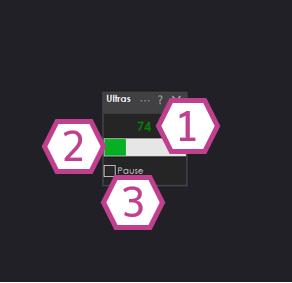
1. Ultrasonic Distance Value
This value between 0-255 corresponds to the detected distance sent by the ultrasonic sensor.
2. Bar Display
Displays a visual representation of the detected ultrasonic distance value.
3. Pause Checkbox
This checkbox pauses the capture of the ultrasonic distance value.
Settings
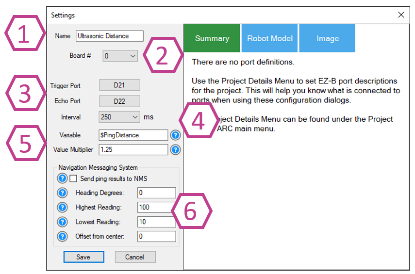
1. Title Field
This field contains the title of the skill. You can change it if you'd like. *Note: Changing the title will also change the title in the controlCommand() associated with this skill.
2. Board Index Drop-down
Select the EZB index number that your ultrasonic sensor is connected to.
3. Trigger & Echo Port Drop-downs
Select the digital port that your ultrasonic trigger wire is connected. Also, select the digital port that your ultrasonic echo wire is connected. *Note: This port must be the same as the trigger port when using a 3-wire Ultrasonic sensor.
4. Interval Drop-down
This drop-down selects the interval rate in milliseconds at which the ultrasonic sensor will be sampled. The range is 100-60000 milliseconds. The default setting is 250.
5. Variable & Multiplier
A variable will be set with the most recent distance value. This saves your code from calling GetPing, which adds needlessly to the communication channel.
The multiplier value will convert the raw distance value to a unit of measurement. For example, the default value of 1.25 will convert the distance into CM.
6. NMS (Navigation Messaging System)
The distance data can optionally be configured to push detected distances into the NMS (Level #3 Group #1) to be used by navigation robot skills, such as The Navigator. Please read the NMS manual and question marks associated with the options for better detail.
Wiring Diagram
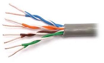
Ultrasonic Distance Sensors come in 2 versions. A 4-wire type with/without an inline voltage regulator and three wires with/without a built-in voltage regulator. If an Ultrasonic has a voltage regulator, it will need +6V or greater Voltage input; if it doesn't, it will need +5V.
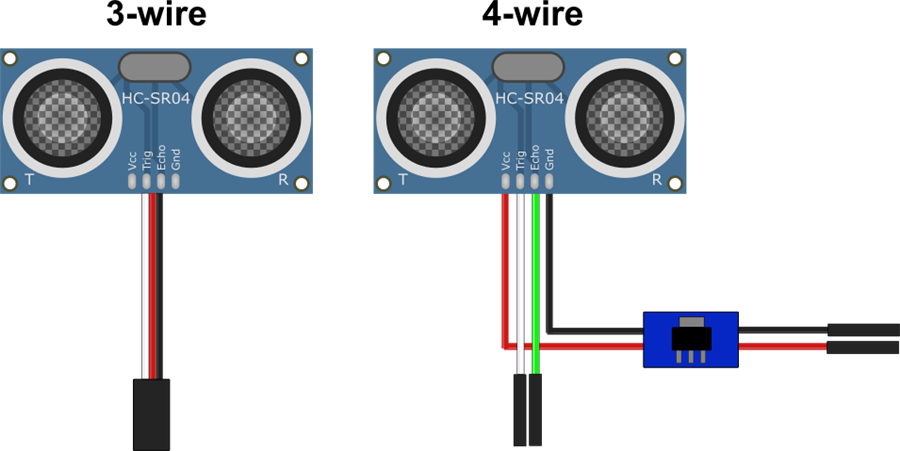
3-wire Wiring (with built-in regulator)
- Ground = Black wire to GND
- Power = Red wire to Vin
- Trigger/Echo = white wire to Digital pin
- Ground = Black wire from regulator to GND
- Power = Red wire from regulator to Vin
- Trigger = white wire to Digital pin
- Echo = green wire to a second Digital pin
Fix Resolution
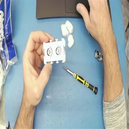
If you use an EZ-Robot ultrasonic distance sensor, there may be false positives from the ping sound echoing within the casing. It is easy to fix with a few cotton balls inserted in the case around the sensors. Watch this video for detailed instructions.
Tech Details
Resources
Synthiam has a ultrasonic hardware reference design here.
Related Tutorials
Related Robots
Related Questions
question
Wire Length For The EZB Ultrasonic Sensor
Hello folks, Figured Id throw this out there and see what others think...Has anyone ever had to install the EZB...
question
How Do I... Not Be Hopelessly Lost?
Im sorry for ANOTHER stupid question, but Im having a REEEALLY hard time following the Tutorials and searching for help...

Upgrade to ARC Pro
Become a Synthiam ARC Pro subscriber to unleash the power of easy and powerful robot programming
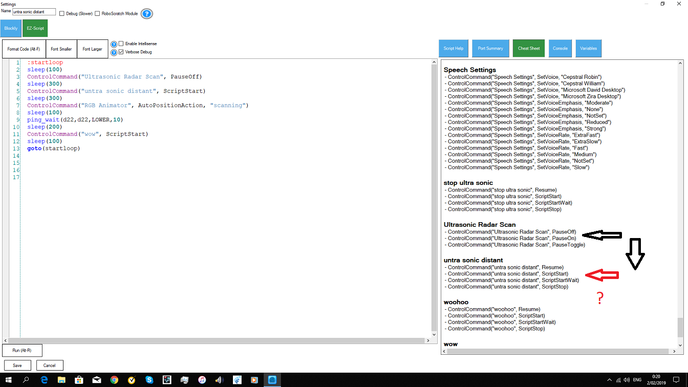
hiis there no ControlCommand pause on or off for the ultra sonic distant?
anyone thank you
:) This control is used for debug purposes only and not necessary for operating. Your scripts that call GetPing() do not need that control added
ah i have to read GetPing()
thanks
$x = GetPing(d22,d22) this doesn unpause the ultrasonic ? i am confused. i use the version 2 ping sensor.
GetPing() doesn't need the ultrasonic control at all. When you call GetPing(), it's separate than the ultrasonic control.
I'll modify ARC to allow you to have ultrasonic distance and call getping() at the same time.
i wanted to use that to get more visual aspects in my ARC.
thank you dj
Hi Guys,
so todays issue on the list of 99999 things to sort is i cant for the life of me get a sonar sensor to work. I am using a arduino leonardo as the ez-b , the sonar is connected to pin 10 trig / pin 11 echo , its powered externally and tried of the board with common earth using 5 and 6v in ARC i set sonar distance to read for the pins and i get nothing except N/A and no reading ? tried 5 diferent sensors as came in pack of 5 no results at all, its unpaused as well .. help :-)
Thanksyou
Review the debug log and the message will be displayed about the latte panda firmware not supporting the ping sensor. It's easy to add though, i can do it for you if you're not familiar with arduino. I'll have time to do that early this week. I'll let you know when it's done