How to add the Ultrasonic Distance robot skill
- Load the most recent release of ARC (Get ARC).
- Press the Project tab from the top menu bar in ARC.
- Press Add Robot Skill from the button ribbon bar in ARC.
- Choose the Ultrasonic Distance category tab.
- Press the Ultrasonic Distance icon to add the robot skill to your project.
Don't have a robot yet?
Follow the Getting Started Guide to build a robot and use the Ultrasonic Distance robot skill.
How to use the Ultrasonic Distance robot skill
Ultrasonic sensors use sonar (sound navigation ranging) to determine the distance to an object or wall, the same way some animals like bats and dolphins do. They offer excellent range and accuracy in an easy-to-use package. Unlike infrared sensors, their operation is not affected by sunlight or black materials. However, they have trouble with soft fabrics; the sonar echo works ideally when bouncing off hard surfaces.When an HC-SR04 or equivalent Ultrasonic Distance Sensor is connected to an EZB, this skill will display the distance of a detected object/wall in front of the sensor. This skill does not cause a robot to steer or avoid obstacles; it merely displays a distance value. For object avoidance and steering use the Radar skill.
This skill is integrated with scripting and will update when GetPing() is called (with matching port configured) and the PAUSE checkbox is checked. That way, you can have this skill on your project, but it won't use any communication resources unless it's called from a script with GetPing(). You can leave the PAUSED checkbox checked; this skill will be updated when GetPing() is called.
It's worth noting that the distance displayed is not a unit of CM or Inches. The distance value is an arbitrary number related to the sensor type, voltage, detected material, and temperature. If a specific distance unit is required, use a tape measure to identify the distance value.
Main Window
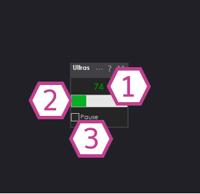
1. Ultrasonic Distance Value
This value between 0-255 corresponds to the detected distance sent by the ultrasonic sensor.
2. Bar Display
Displays a visual representation of the detected ultrasonic distance value.
3. Pause Checkbox
This checkbox pauses the capture of the ultrasonic distance value.
Settings
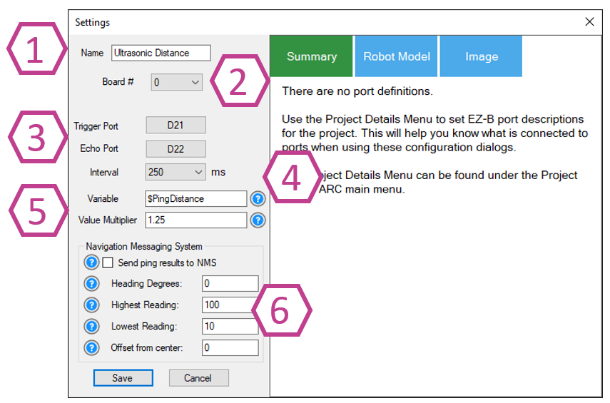
1. Title Field
This field contains the title of the skill. You can change it if you'd like. *Note: Changing the title will also change the title in the controlCommand() associated with this skill.
2. Board Index Drop-down
Select the EZB index number that your ultrasonic sensor is connected to.
3. Trigger & Echo Port Drop-downs
Select the digital port that your ultrasonic trigger wire is connected. Also, select the digital port that your ultrasonic echo wire is connected. *Note: This port must be the same as the trigger port when using a 3-wire Ultrasonic sensor.
4. Interval Drop-down
This drop-down selects the interval rate in milliseconds at which the ultrasonic sensor will be sampled. The range is 100-60000 milliseconds. The default setting is 250.
5. Variable & Multiplier
A variable will be set with the most recent distance value. This saves your code from calling GetPing, which adds needlessly to the communication channel.
The multiplier value will convert the raw distance value to a unit of measurement. For example, the default value of 1.25 will convert the distance into CM.
6. NMS (Navigation Messaging System)
The distance data can optionally be configured to push detected distances into the NMS (Level #3 Group #1) to be used by navigation robot skills, such as The Navigator. Please read the NMS manual and question marks associated with the options for better detail.
Wiring Diagram
Ultrasonic Distance Sensors come in 2 versions. A 4-wire type with/without an inline voltage regulator and three wires with/without a built-in voltage regulator. If an Ultrasonic has a voltage regulator, it will need +6V or greater Voltage input; if it doesn't, it will need +5V.
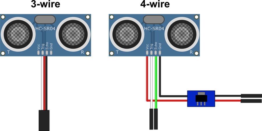
3-wire Wiring (with built-in regulator)
- Ground = Black wire to GND
- Power = Red wire to Vin
- Trigger/Echo = white wire to Digital pin
- Ground = Black wire from regulator to GND
- Power = Red wire from regulator to Vin
- Trigger = white wire to Digital pin
- Echo = green wire to a second Digital pin
Fix Resolution
If you use an EZ-Robot ultrasonic distance sensor, there may be false positives from the ping sound echoing within the casing. It is easy to fix with a few cotton balls inserted in the case around the sensors. Watch this video for detailed instructions.
Tech Details
Resources
Synthiam has a ultrasonic hardware reference design here.
Related Tutorials
Related Robots
Related Questions
question
Wire Length For The EZB Ultrasonic Sensor
Hello folks, Figured Id throw this out there and see what others think...Has anyone ever had to install the EZB...
question
How Do I... Not Be Hopelessly Lost?
Im sorry for ANOTHER stupid question, but Im having a REEEALLY hard time following the Tutorials and searching for help...
Upgrade to ARC Pro
Unleash your robot's full potential with the cutting-edge features and intuitive programming offered by Synthiam ARC Pro.
hi
is there no ControlCommand pause on or off for the ultra sonic distant?
anyone thank you
:) This control is used for debug purposes only and not necessary for operating. Your scripts that call GetPing() do not need that control added
ah i have to read GetPing()
thanks
$x = GetPing(d22,d22) this doesn unpause the ultrasonic ? i am confused. i use the version 2 ping sensor.
GetPing() doesn't need the ultrasonic control at all. When you call GetPing(), it's separate than the ultrasonic control.
I'll modify ARC to allow you to have ultrasonic distance and call getping() at the same time.
i wanted to use that to get more visual aspects in my ARC.
thank you dj
Hi Guys,
so todays issue on the list of 99999 things to sort is i cant for the life of me get a sonar sensor to work. I am using a arduino leonardo as the ez-b , the sonar is connected to pin 10 trig / pin 11 echo , its powered externally and tried of the board with common earth using 5 and 6v in ARC i set sonar distance to read for the pins and i get nothing except N/A and no reading ? tried 5 diferent sensors as came in pack of 5 no results at all, its unpaused as well .. help :-)
Thanksyou
Review the debug log and the message will be displayed about the latte panda firmware not supporting the ping sensor. It's easy to add though, i can do it for you if you're not familiar with arduino. I'll have time to do that early this week. I'll let you know when it's done
That would be great m8 , i am using a seperate arduino leonardo though , not the on board one does that make a diference ? i do have a microbit woud lthat support it just for testing ?
Does not look like the microbit has support for it either. The arduino uno does though: https://synthiam.com/Firmware/Delicious-Arduino-Uno-MMNJADDIIPY
Ok, i may jusy wait till you sort the leonardo firmware if thats ok , can you advise when its sorted plz
Ya my Latte Panda is also half Leonardo along with Win10 but I have yet to use it for any Arduino programs The Win10 is just so much easier to use with all my Io Tiny controllers where all sensors work instantly and programming is done in minutes instead of days with Arduino coding.
Any updates on the firmware to get sonars working on the arduino yet ? pretty please :-)
Thanks
I published the changes in the next build so it will go out when the build is published. I think it’s schedule for early next week
Is this now working on arduino ? has the build been updated
Thanks
Ironically I see the update scheduled for this evening
I have an update regarding DJ's response. He was unaware of maintenance on the build server yesterday, so the update was postponed for today.
I am having an issue getting any response from my HC-SR04 4-wire ping sensor. I have tried two other ping sensors including an EZ-Robot sensor. I checked my power and checked the trigger and echo lines again and again. I tried it with 3 different skills and then with "getping(d1,d2)". Nothing seems to work. I just get back "255" and nothing else.
Does anyone have any suggestions? I have been trying to debug this for two days.
Thomas
Maybe you have the trigger and echo wires reversed? Also, ensure you're powering the device with 5v because those sensors will be immediately damaged if powered directly off a battery.
I tried reversing the trigger and echo wires and I had the same problem. I am powering the sensor from a + (red) terminal from the EZ-B. I measured 5.7 volts.
Check the sensor's datasheet and ensure it's within the operating range. I guessed 5v, but it could be 3.3v; not sure.
5 volts.
I give up. It’s one of the simplest sensors to interface, but after several days of no success, I have come to the conclusion that It just won’t work for me. Sigh.
So I did find a workaround. I am now using an Arduino for the ping sensor and then sending the signal to the EZ-B as a digital input. Now THAT works!
hi dont you need to use one off these ?for the ezbv4 ?
regulator
Hello Thomas,
I understand you contacted EZ-Robot about this issue. I figured I'd continue the conversation here.
I tested a 4-wire Ultrasonic today and everything worked well. Both in scripting and in the skills.
You must have a broken jumper or a regulated 5V isn't being supplied to the sensor.
You said you are supplying 5.7V, try using 5V. From the datasheets I've seen, it says it needs 5V, 5.7V is likely too high.
Here's my setup (with a 5V regulator):
Here's the EZ-Script I used:
Here's the JavaScript I used:
Here's the result, you can see the data in the console on the right:
I am using EZ-Script. I will try JavaScript later today.
I really think you have something hardware-related going on. I don't think JavaScript will help, I posted it just in case someone in the future wanted a JavaScript example and because JavaScript is my default these days. I wrote the original example in JavaScript, it took me a bit of time to translate it to EZ-Script for you as I've now forgotten it.
I'll try replacing all of the wires on the weekend. I will measure the voltage coming out of my regulator. I will also try powering it off of another power supply. Ping sensors SHOULD WORK!
I can assure you they do work, as shown in my post above!
Unless they were damaged by overvoltage...which may have happened.
Using my ping sensors with external 5 volt battery source I always had to make sure negative grounds were all linked to negative on EZ controller negative source or I would end up getting crazy high and low values that made no sense, specially with 2 ping sensors.
I have yet to get a ping sensor working with ARC and my EZ-B. I am totally stumped at this point and I really do not wish to use an Arduino WITH MY EZ-B. (Yes, that worked. See above.) Since I have gotten nowhere after weeks of troubleshooting, I am offering $50 USD (payable by paypal.com) to the first person who can solve this issue for me to my satisfaction. Contact me directly at thomasfromla at g mail dot c0m. Show me where I went wrong! I will respond here when the problem is solved.
Thanks,
Thomas
hi tmessersmidt
i found this picture . you can take a blank new project and use only the sensor there . see what happens .
tmessersmidt
it looks like the power is wrong connected . see post 24 from jeremie . he has diff color connected.
Thomas can I copy and paste the response I made above and claim the reward?!?
I probably used an hour of work time to do a demonstration and then make a post about it with sample code.
There's something going on with your hardware, you may have overvolted the sensor. It's a mystery why it would work with the Arduino. I recommend grabbing another ultrasonic to test with, they are fairly inexpensive and prevalent.
hi jeremie
your right . your colors in post 24 are diff connected then in post of messersmidt in post 22
Thanks for pointing that out @Nomad it’s definitely possible that the Ultrasonic was damaged due to reverse polarity as well.
I did have a hunch that the sensor could be working with the Arduino because the chip on the sensor has been weakened but not completely blown, you see the Arduino uses a higher TTL than the EZ-Bv4. The Arduino used 5V TTL and the EZ-B is at 3.3V TTL.
I have seen odd things happen like that when electronics are slightly damaged by over voltage or reverse polarity.
I recommend trying a new Ultrasonic sensor.
Jeremy/Nomad,
No, you cannot claim the reward because I still cannot get any ping sensor to work. Sorry.
Gee. No takers on the $50. I thought it would take some bright robotics genius no more than 5 minutes to figure out my issue. Sigh.
messersmid
am not doing it for the reward . am doing it to learn to recognize errors . if 7 sensors work and only one doesn .that means jeremie is correct . its hard to see burn stuff on circuitboards .
No sensors have worked with the EZ-B. All of the sensors have worked with the Arduino.
ah then the ezbv4 is the problem not the sensors . can you open the ezbv4 for inspection , burn spots ?
if all 8 sensors stil works on the arduino today? a or one doesn ?
does the 7 sensors works on the ezbv4 ? if not the problem can be the ezbv4 .
Nomad, no burn spots on the EZB. All 8 ping sensors work on the arduino. No ping sensors work on EZB. I tried a touch sensor on the EZB and that worked perfectly.
hi TMessersmidt
a touch sensor is diff then a ping sensor . can you try another voltage regulator ? are you using this one ? and its not backwarts connected ?
here's a picture .
Yes, I can read "IN" and "OUT" on my voltage regulator. Yes I tried another voltage regulator.
hi
am asumming the in goes in the rgb and out on the ezbv4 .
Yes. Of course. I have increased the reward to $100 USD.
Also, I have made a video documenting the issue:
Click for my YouTube video describing the issue.
I need to solve this problem. I wish Synthiam would help me.
what happens when you use a 7.4 volt batterie ? rechargeble give only 1.2 volt per bat .
should that not be
:loop
goto(loop)
Nomad,
I don't have rechargeable batteries.
This loop works. The "GetPing(d1,d2)" does not. :
Thanks for trying.
Thomas, I’m unsure if you know that I am working for EZ-Robot and am offering you customer support here. There’s not much more @DJ can really help with as the software works fine. Do you have the most up-to-date software?
I’m not looking for the reward money either.
It looks like you need to dig deeper into your hardware, check voltages, check continuity. In theory what you have there should work but there’s something unforeseen.
jeremie
indeed the rgb is facing down . would it not be easier to use the radar window ? there you can see it working .
Can you show me the voltage out of the regulator with the connected ping sensor?
Also, in your video, the sensor is facing down. That will return 255 because there’s no echo, and it cannot operate within the specifications of the sensor's datasheet. There’s a great video on how to connect that sensor to an ezrobot product above on this page. I posted the video below to save on scrolling.
Notice in this video where the sensor is pointed during testing by Jeremie. It will be essential to test the sensor within its capabilities to know if it is working. Otherwise, you may have the sensor connected correctly and working, but it cannot operate within the confines of your test.
If you hold your ear to the sensor, you should hear an audible click each time the sensor is reading the distance. That will help you determine if the sensor is faulty or if the trigger/echo wires are reversed.
I'll just throw this idea out there. Try adding a longer sleep to give the device time to react? Change it from 100 to 1000. FYI I've never used a ping sensor but I've never heard anyone having this kind of trouble and seen lots of users of this hardware over the years. Good luck with your issue. I have a new ping sensor here I've never used and a new EZB. If I have time tomorrow I'll play around with it to see if I can get it to work. Sounds like a fun little project. I'll let you know.
DJ, 4.8 v DJ, 4.8 volts coming from the regulator with no sensor. 4.7 volts coming from the regulator with the ping sensor attached and running. I had the sensor pointing away, but the bend in the wires kept directing it downward. But, down or up, I get the same 255 results. No clicking is coming from the sensor while plugged in and running. Thanks for helping me troubleshoot this issue.
David, Thanks. I tried slowing down the sleep to 1000 as you suggested. No improvement.
Nomad, Thanks. It was only facing down for a short time. Up or down, it does not work.
Jeremie, No, I did not know that you worked for EZ-Robot. I have the latest ARC update. I tried to connect with EZ-Robot via Facebook, but no one replied.
Thanks everyone,
Thomas
so the sensor is death . no clicking .
The sensor is dead if connected to the EZ-B, but alive if connected to the Arduino.
as long the other 7 are working on the ezbv4 ,then you have made one for arduino special edition .
Well Thomas, I pulled out all the stops for you.
Thank you for mentioning the voltage and swapping the jumpers.
I reached deep into my HC-SR04 Collection and tested 3 different sensors. The top 2 look similar but they do have minor differences you can see that the crystals and the "HC-SR04" silk screen have slightly different fonts on them.
You could compare your sensors to mine and see if they match the sensors I have.
I tested all the sensors with your EZ-Script code - All 3 were good, super low numbers with objects in close proximity and higher numbers around 100 when aimed at my ceiling.
I tested them with a lower voltage - All three were good down to 4.7V, and the bottom sensor surprised me with accurate readings down to 3.6V. This proves that there are differences between brands.
I had a hunch that maybe you bought a certain brand of HC-SR04 that requires a slightly different trigger pulse than ARC produces but from the spectrum of sensors I own, it seems that this is not the case. If your sensors do look quite different than mine, maybe there is validity to the hunch.
Do you know the exact trigger pulse width that the Arduino produces? If not, do you have an oscilloscope?
Can you move a servo with the d0 and d1 ports of that ezb?
disconnect the ping sensor, start a new ARC project, add a horizontal servo control, move the servo. Can you move a servo on those ports with that ezb?
Thomas, I feel for you man. I know how frustrating something like this is. It sounds like you have tried everything.
When I get to this point (and I do at times) I shot gun everything and start new with as many new parts I can. In your case that may not be feasible.
One thing occurred to me. It's possible that you may have a broken jumper wire, connector, header pin that only makes contact when moved in a certain direction. These are hard to find and oddly and randomly intermittent. I just had this issue a couple weeks ago and it was driving me crazy. I found it after DJ suggested a lose connection and I did some continuity tests.
Troubleshooting is an art and very methodical. It's tedious at times and frustrating. I have a few steps to suggest. Some of the steps may seem redundant or silly but you would be surprised how many times I felt the same way only to try it and uncovered a hint as to what is going on. You may have already done these things but I'll list them anyway. When I say test below I mean a continuity test. *Pull all the wiring apart. Do a continuity test on each wire from tip of connector to tip of connector. Do this while moving the wire and connector around. Be aggressive. Make sure you have a good positive connection from the tip of each wire to your testing meter. *Put the wiring back together and test continuity from feed to source. Again while moving the circuit around. *After wiring is in place test form header pin solder joint on the boards to header pins solder joint on the board if possible. I've seen many cracked solder joints or even cold solder joints on boards. I repair old pinball machines from the '80's and 90's and this is a common problem. This translates to robotics. Again, move the connection and wires around. *New jumpers and connectors can also have broken or bad connectors so don't assume just by replacing the wiring you have solved your problem. *Move the confirmed good wiring to different ports on the EZB. Remember to change the port assignment in ARC in your script. Double check your settings. Triple check your settings. *I've had scripts in ARC stop working when I was working on them or rewriting them. It's happened rarely but it happened. The only way I was able to get the script working again was to totally delete it, reboot ARC, open up a new script and rewrite it from scratch. *Move the voltage regulator to before the EZB and feed the EZB through it. Then attach the positive and neg of the sensor directly to the EZB power pins. Power up and move the regulator around aggressively. See if the EZB browns out, reboots or flickers. *Run power directly to the sensor through a known good regulator and not through the EZB. Run a different power feed to the EZB. *If you have a different (maybe even adjustable) voltage regulator try using it. *Double check the input voltage requirements of you're regulator and make sure you are feeding it within the spread. I know the EZB Ping Sensor that you say you tried has a input voltage of between min 6.2v, max 20v. Your little 6v battery pack was probably not giving it enough power. *Replace your batteries with new ones. *Try a different power source. I hate those little battery packs. I know you're not drawing a big load but we're troubleshooting here. Give it more overhead. Do you have a switching power supply like a computer power supply? Try it and feed it 12 volts and buck the voltage down to within the sensors specified voltage with an adjustable converter. *Double check, triple check all your wiring and connections. *Maybe you have two simple issues that are popping up different times making this look completely broken.
If you're totally frustrated you may be missing something or even simply overlooking a simple detail. Man, I've been there. Maybe a fresh set of eyes would help. If you are open I'd be happy to look at it personally. Just ship the components you're having trouble with to me and I'll try my luck. I'm no expert but I may be able to see a thing or two you have missed. I do not want your money. My email is dschulpius@gmail.com.
@Thomas I definitely back up what @DJ and @Dave are saying.
When executing your script you should hear the clicking (pulsing) of the Ultrasonic, even if you reverse the trigger and echo pins you'll still hear the Ultrasonic clicking if you place the sensor close to your ear. If you can't hear anything then move then check continuity and voltages as Dave was mentioning, and wiggle wires around if you have to. I do find that those AA battery holders do have flimsy wires that break every once and a while.
If it's not a bad jumper wire and 5V regulated voltage is getting to the Ultrasonic (check with a multimeter at the sensor pins), then it seems like it could be the EZ-B ports. You could try what @DJ mentioned and test the EZ-B pins in particular by simply using a servo on them.
I did find that one of my Ultrasonic sensors was reading 255 all the time, turns out that it had a broken capacitor. As you can see here directly in the middle of the photo.
DJ & Jeremie,
I am using d1 and d2. I hooked up a servo to d1 and it works fine. I then moved it to d2 and that worked fine as well. The ports work fine. See Video.
https://youtu.be/20St84CSUyQ
Also, my sensors are nothing like Jeremie's. Tonight I tried an old (10 year old?) VEX ping sensor that I had and IT WORKED! I'm thinking there may be a compatibility issue with my new sensors. You see, I recently bought 10 "Smraza" brand ultrasonic sensors from Amazon.com (They were cheap!) https://a.co/d/9RyU9PH . Those 10 are the ones that are NOT working with an EZ-B. Again, they work with an Arduino.
Can you recommend some (not too expensive) ping sensors that have worked for you two?
Dave,
Thanks! I think I might have solved the issue.
Thomas
My cheap "Smraza 5pcs Ultrasonic Module HC-SR04" sensors:
Awesome! Thanks for checking that Thomas, looks like maybe my hunch in post #58 was correct.
I've ordered the Smraza sensors to try here in the EZ-Robot lab and they will be here on Thursday.
I have also ordered the next cheapest Elegoo HC-SR04 sensors and they will be here today (Wednesday). My hope is that the Elegoo sensors will work natively with the EZ-B and you could switch over to those.
What code do you use on the arduino for that sensor to work. Copy and paste an example code snippet so we can see.
DJ,
The code I used is simply the sample code included in the Arduino IDE.
I tried porting it manually in ARC, but could not figure out how to get a microsecond delay.
Thomas
You can’t port it to arc. That’s code for microcontrollers. That’s the same pulse values as the ezrobot ezb uses anyway because it is universal, and the code is not why those sensors do not work with the EZB.
The sensor works with that particular Arduino model you tested because it has +5 gpio, whereas all modern Arduino and micros (such as esp32 and ezrobot stm32) use 3.3v. The 3.3v output signal of am ARM micro, such as in the ez-robot ezb, is too low for their knockoff chip to register. You do not hear an audible click because the 3.3v is too low to trigger the sensor.
You could get those to work by using a light pull-up on the v5 input. I read that issue in the comments on Amazon on the Canadian site.
While you said it worked with "Arduino," you mean it worked with 5v gpio, not 3.3v. It's not that it worked with Arduino; it worked with that particular older Arduino model that uses 5v gpio. Newer micros and Arduino use 3.3v gpio; therefore, that sensor would not work for them either. It would work if you added a pullup resistor from the 5v supply line to the trigger.
Suppose you added maybe a 20k ohm resistor (that's kilo ohm) between the trigger and VCC. That might make those work with 3.3v logic. Remember, some 3.3v logic can read 5v but only output 3.3v. That's in the ezrobot ezb datasheet.
Or, you can just put the EZB firmware on that Arduino and use it - but it'll have to be connected to the PC via USB because that Arduino lacks wifi. Any newer Arduino that supports Wifi (etc. ESP32) will be 3.3v, and you'll need to modify the sensor.
I've used so many of the HC-SR04 sensors that were the same and clones of each other that I hadn't even considered that a company would add a chip with different specs on their sensor. I think @DJ is right, it's likely that a 3.3V trigger pulse from the EZ-Bv4 isn't a high enough signal to cause the trigger to pulse on that specific chip.
As DJ mentioned you can add resistance between the trigger and Vcc pins to pull the trigger signal up closer to 5V. While a 20kOhm pull-up resistor may work, you may have to try different values to make a stronger/weaker pull-up if it doesn't. I'd suggest using a 100kOhm potentiometer first. That's what I'll do when I receive the Smraza sensors, I'll start with a high resistance, trim the potentiometer down, test, and repeat. Once I find a resistance value that works I will find a standard resistor value just below the value.
Be forewarned though a pull-up may not work in this case as it may keep the trigger pin constantly high. If the pin is held high and the EZ-B's signal can't affect the trigger pin, then it still won't work, because the sensor can't transmit.
See how the HC-SR04 sensors work here
I believe the ideal solution, in this case, would be level shifting, which can be done with a dedicated chip or transistors (or Mosfet). We can't use a crude resistor voltage divider in this case as we need to step up from 3.3V to 5V. Voltage dividers are commonly used for stepping logic levels down from 5V to 3.3V.
Here's an example of a bi-directional logic level shifter:
Premade Logic-level shifting circuits are also a pretty decent price on Amazon
Or use two resistors to shunt to ground. That might be needed for accurate distance trigger. Because the waveform might be too slow with only a pull-up resistor.
R3 will allow to shunt to ground any current coming from the 5V (instead to 3.3V through the output pin), when the output is at 3.3V.
Hi @DJ I'm not sure if you read this part of my message:
You've posted a voltage divider circuit, which can't step the logic level up to 5V on the sensor side like Thomas would need.Here's a Hackaday article about level shifting: https://hackaday.com/2016/12/05/taking-it-to-another-level-making-3-3v-and-5v-logic-communicate-with-level-shifters/
Look again, that will step up if r1 is less than r3. R1 will pull the signal high toward 5v. R3 will more gently pull it down toward zero to help the ezb’s gpio.
im guessing it would work with only a pull-up on the trigger. But there are many other more reliable solutions for Thomas’s $0.50 knockoff sensor. My suggestion ultimately would be to buy a reputable sensor.
That's correct. But here's the thing, the output voltage from the voltage divider will always be a fraction of the input voltage (5V). In this case, 5V drops with whatever R1 resistor you add. In order to keep the voltage at a higher level, the R1 resistor will have to be lower in resistance than R3. This means that the logic signal will be kept high as a default. If I'm not mistaken the HC-SR04 needs a low to high 10uS pulse on the trigger line. If the EZ-B can't bring the voltage level down a low to high pulse can't happen.
I'll test the Elegoo HC-SR04 sensors tonight, they would be an affordable alternative.
thats exactly why r1 is lower resistance than r3. R3 only assists the pull down to ease the ezb’s gpio. R1 will pull-up to 5v. The higher resistance r3 will provide a very very minor pull down to 0. This helps the gpio transition quicker between logic pulses.
I have an oscilloscope that says otherwise
The logic is held high and can't go low in the scenario you describe.
Well then! Figure 9 of this page has a compelling formula. The formula will help identify the resistor values for a successful test: https://next-hack.com/index.php/2020/02/15/how-to-interface-a-3-3v-output-to-a-5v-input/
Lol, that's the page I was referencing! Unfortunately, as I described above, a voltage divider configuration only works in a step-down scenario, not a step-up. The R1 resistor is too strong of a pull-up in the step up scenario. Lower resistance means lower path of resistance to 5V aka stronger pull-up. The signal stays high. I tried what you described, and have proven with an oscilloscope that it doesn't work, sorry man.
Anyway, I received the Elegoo Ultrasonics, and this will be vindication for Thomas, they also don't work with the EZ-Bv4 and ARC. All 255 all the time. I do hear clicking though so the trigger seems to be working. I tried 5 of them and they all produce the same results.
I am at home at the moment so I don't have a ton of equipment to work with but just in case I did try a 100kOhm pullup with a potentiometer from the trigger to VCC pins on the Ultrasonic and tested it at intervals all the way down to 0 ohms. Still all 255 readings all the time.
I will try a level shifter circuit later tonight and let you know, my hunch now is that the issue is on the echo side since I can hear the sensor pulsing. So they may produce an echo signal that's different than what ARC is expecting.
Oh yeah, the echo could be it as well. Many people on the internet appear to have the same issue with some knock-off hc-sr04 distance sensors on modern 3.3v micros. As microcontrollers get faster, they need less heat which means less voltage... so don't expect that to change any time soon
While in the shower today I was going over a few thoughts about this issue. I did realize that I was missing something in terms of using a voltage divider to step up the logic voltage level. I was using low resistance values (R1 = 220 ohms, R3 = 2200 ohms) and this makes for a very strong R1 pullup so much so that the EZ-B can't pull the signal down. So today I tried very high resistance values (R1 = 22 kohms, R3 = 220 kohms) and found that the EZ-B could pull the signal down, but unfortunately with this weak of a pullup the signal was no longer raised in its voltage level (stayed at 3.3V). While I could try and dial in the values to see if there would be a precise happy medium, this isn't actually related to the issue we are facing with the 255 readings so it's really chasing ghosts.
While reading the trigger signal of the Elegoo and Smraza Ultrasonics (which both only read 255 all the time) under the scope I found that the trigger pulse isn't being affected, it's a precise 10uS at 3.3V from the EZ-B. Which is expected.
When comparing to an HC-SR04 Ultrasonic that works, they are nearly identical:
Here's the Echo screenshot from the Elegoo/Smraza at a 3cm distance to a flat surface:
Here's the Echo screenshot from the Good Ultrasonic at a 3cm distance to a flat surface:
The echo voltage level from the Elegoo/Smraza sensors is 5V as expected, and it's surprising that an Echo signal is actually being produced, but I did notice that the echo signal is a bit wider on the Elegoo/Smraza than the good sensor. I would not expect a wider (slower) signal to be reading 255 rather I would expect it to just read a little higher in value than the good sensor (ex: should read a value of 10 instead of 3, not 255).
I'm at a bit of a loss as to what the issue actually is, it seems like everything that is needed is there.
The longer pulse width is the distance. So the knockoff sensors return are returning a much longer pulse.
I really am running out of energy on this subject. The sensors are out of spec and have consumed way too much of my time. So I’ll leave you with this question. Does that pulse width change with closer objects?
i ask because that pulse width is the same width as infinite on a standard hc-sr04. That knockoff sensor might be always returning infinite or it’s pulse width on echo is always a bit longer.
You’d need to test on the ezb with a variety of distances - not one. Id recommend 15cm, 30cm, 50cm, 100cm, 200cm, and infinite
One thing I did find is that the Echo signal pulses come in at a rate of ~4MHz with the good Ultrasonic sensors and ~7MHz with the Elegoo/Smraza sensors. So it seems the Elegoo/Smraza sensors do have an Echo reading coming in at a faster rate.
It's difficult to get an exact frequency as the Echo signal from all the sensors is a bit sporadic and isn't a clean repeating waveform.
*Edit: I guess I was writing my comment at the same time as you @DJ, I'll have a look at your suggestion.
Oh and the answer to your question is yes the Echo pulse width does move as the sensor is pulled further away from a flat surface. The Echo signal grows wider as expected the further you move it away.
While I don't have time to try all those distances, I will try a few and let you know.
Here are the results:
15cm Good
15cm Bad
30cm Good
30cm Bad
100cm Good
100cm Bad
Infinite Good
Infinite Bad
They look very similar to each other. I am baffled.
Hahaha, now that is funny because they're acting the same! I believe you found some sentient distance sensors that do not want to be discovered.
How about the time between trigger and echo?
Okay, here's the code for the EZB's ping sensor.
The first WHILE loop is waiting for the start of the ECHO pulse. The second WHILE loop is waiting for the end of the ECHO pulse. Both have a timeout. Essentially, the WHILE loops together are the replacement for Arduino's "pulseIn()" command.
The part that i bolded (first WHILE loop) will matter if the sensor takes too long to return before receiving the start of the echo pulse. So if you can check the time between trigger and echo - that would probably tell us what's going on with the knockoffs
Sorry, no screenshots this time but I believe you have found the culprit!
Bad trigger to Echo separation is 2.25mS
Good trigger to Echo separation is 500uS
Looks like the arrival time of the Echo is way slower on the bad sensors.
*Edit: If anyone is curious, I found the main chips used on these sensors: RCWL-9300 (Microcontroller), RCWL-9206 (Communication IC), LM324 (Quad Op-Amp)
Some of the good sensors have SGM324 (Quad Op-Amps)
Yeah, that's it. So the knockoff sensors are super slow and timeout. That's a good thing we discovered because the ping sensor is a blocking function on microcontrollers and will pause all communication while waiting for the echo pulse to complete. Those sensors would make any robot super duper slow because there would be a >2ms delay for every reading. Wow, those are terrible sensors. Two milliseconds in electronics is forever, specifically when blocking communication or other I/O commands. A slow sensor would result in robots driving into walls because it can't send communication fast enough while it waits for the sensor readings to complete.
I'm guessing the microcontroller programmers of the knockoff sensors didn't know how to write the code efficiently. So their code takes too long to execute and blocks for >2ms.
While Arduino's "pulseIn()" on the Arduino EZB Firmware will wait up to 3 minutes, it would work with the knock-off sensors. However, I would not recommend it because the blocking time waiting for an echo will cause significant performance issues.
DJ,
You're welcome. You'll get my bill.
Thomas
What am I welcome for?
For thanking me for finding the issue. I told you that you would need to hire me one day .
This was not an issue.
:) That's what all programmers say.
Guys, so what brand of ping sensor should I buy for my EZ-Bv4? I tried an Elegoo and that didn't work.
The EZ-B v4 natively supports the EZ-Robot ping sensor because it is their sensor. As for the current sensors you are referring to, you can use the Arduino EZB firmware. However, if you use the Arduino EZB firmware with those knock-off sensors, you will experience communication delays.
Smraza, HiLetgo, Elegoo, EpLzon, 10Gtek, Aoicrie, Aceirmc, and dozens of others seem to be made by the same factory. Is there some specification that I need to look for?
I see. OK. So I need to buy sensors from EZ-Robot for $27 USD each. Is that what you are saying?
EZ-Robot has products that are known to work with their EZB controllers. So, I would recommend those if using an EZ-Robot controller. You can use the sensors you mentioned with different EZB firmware, such as the Arduino EZB firmware.
I do not work for EZ-Robot and can't speak on their response - but as a user like yourself, I would assume they would prefer you use their sensors for a positive experience because they guarantee they work. As you have experienced, many knock-off sensors are available that do not conform to the ping HC-SR04 standards.
hi messersmidt
you can by the sensor without the case 17 dollar .
sensor 17dollar
DJ,
I got it. I guess I'll stick with my first solution of using the Arduino with Arduino code to monitor the sensors and then feed that to the EZ-B. I want to keep the EZ-B with my current project so that I can plug in a camera, output sound, and have all of those 24 digital I/O ports. Yes, I know I could use an Arduino Mega or some larger version of Arduino with a wireless camera and Bluetooth speakers.
Jeremie, I suppose altering the EZ-B to allow the cheaper ping sensors would be a large & costly upgrade for EZ-Robot and probably out of the question. Yes?
Thomas
I don't know of a larger Arduino with wireless, but an ESP32 would work. The ESP32 firmware doesn't currently support HC-SR04, but I have added it to be added in a future release. All ESP32 Arduino's are wifi enabled and come in various form factors. There are an unfathomably high number of ESP32 form factors, so you'll have to decide what has the appropriate I/O for your needs.
While I would first and foremost recommend the EZ-Robot Ultrasonic, thank you @DJ and @Nomad, as it is tested to work 100% with the EZ-B. I can see it being quite expensive if you are trying to use an array of these sensors on a DIY robot.
Here's what you need to know when purchasing HC-SR04 ultrasonics. All of the new style sensors are removing components to make more profit. It looks like the removal of these components causes these sensors to be slower (>2mS wait times per pulse). The older version sensors you want still have the load caps by the crystal and still have transistors on board.
If these components are missing you have a new and NOT-improved sensor.
It's not in my best interest to send you back to amazon, as we would love everyone to continue to support EZ-Robot with your hardware purchases, but I also don't like to be a gatekeeper so I'll say this: These sensors are still available online, I found some myself a few minutes ago that are $4CAD each, you have to wait a week to get them though.
Sorry Thomas, changing the EZ-Bv4 to support a sensor that we don't sell isn't in the cards.
@Dj and @Jeremie, I for one appreacheat all the time and effort you two put into this issue. It shows that you want to keep your product's quality high and you really care about us as users. I've never been disappointed in the support you all have offered. In fact you're commitment to keeping your products the best in the business and your customers on all levels up and running has alway been and continues to amaze me. I've never seen anything like this in any other company out there. Thank you!
@TMesserschmidt, I hope you write about that in one of the articles you author.
hi dave
i agree with you . use parts that belong to a brand . dj&jeremie well done masters .
If I were to use EZ-Robot's sensors, it would be an expensive project because I need 10 ping sensors. I'll take a look for the ping sensors that Jeremie is suggesting.
Thanks to everyone who assisted with this issue.
Thomas
TMesserschmidt
maybe you get a discount if you by 10 sensors from ez robot .:) if you would by 10 random sensors , howmany arduino would you need to , get them all to work ?
Nomad,
thanks for the suggestion.
Thomas