Control up to 127 stepper motors as servos with speed and acceleration.
How to add the Stepper Servo robot skill
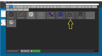
- Load the most recent release of ARC (Get ARC).
- Press the Project tab from the top menu bar in ARC.
- Press Add Robot Skill from the button ribbon bar in ARC.
- Choose the Servo category tab.
- Press the Stepper Servo icon to add the robot skill to your project.
Don't have a robot yet?
Follow the Getting Started Guide to build a robot and use the Stepper Servo robot skill.
How to use the Stepper Servo robot skill
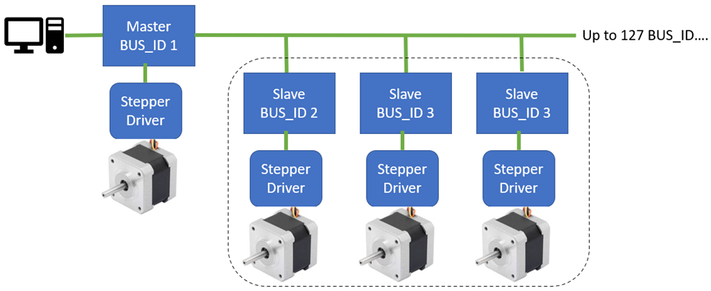
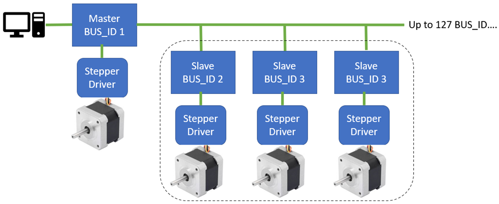
Control up to 127 stepper motors as servos with any stepper motor driver or motor type. This robot skill requires a low-cost and small-profile Arduino connected to each stepper motor driver. Each Arduino is given a unique ID on the optional serial network. All 127 Arduino will share the same PC COM port via the first Arduino's USB connection. An optional end-stop limit switch can calibrate the stepper's home position.Operating Modes
Each Arduino's firmware has a configuration for specifying the operating mode. There are four modes, SLAVE_SERIAL0, SLAVE_SERIAL1, MASTER_SERIAL0, and MASTER_FORWARDING. They are explained below, and only one of the modes can be active based on your configuration and hardware.
MASTER_SERIAL0
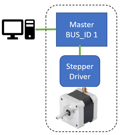
This mode uses a single Arduino over USB with no additional Arduinos connected to the serial network.
There is no serial network for this setting. This is for a single Arduino with one stepper.
Enable MASTER_SERIAL0 if all of these conditions are met...
- this is the only Arduino that will be connected to the PC (i.e., you only need one stepper motor)
- this Arduino is connected to the PC via the USB cable

MASTER_FORWARDING
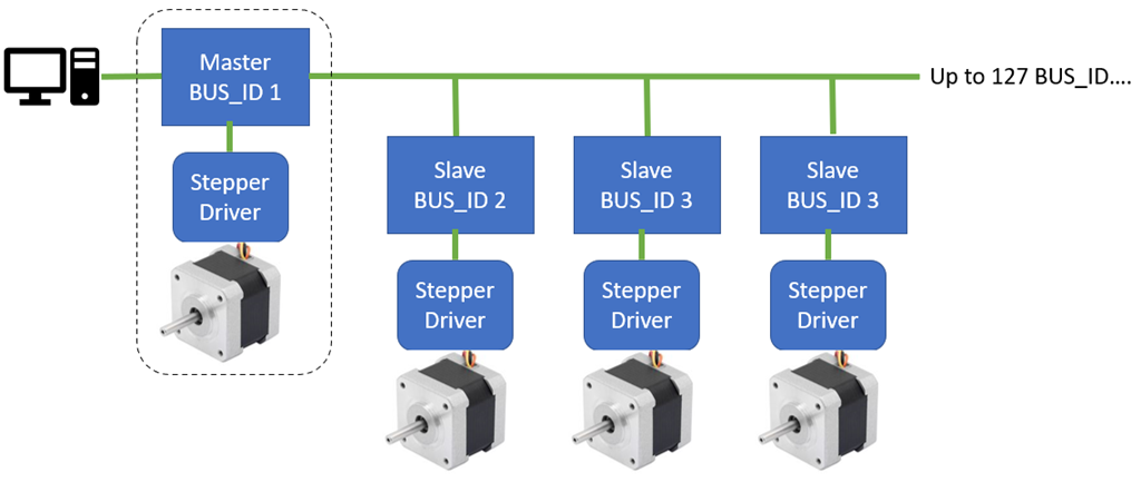
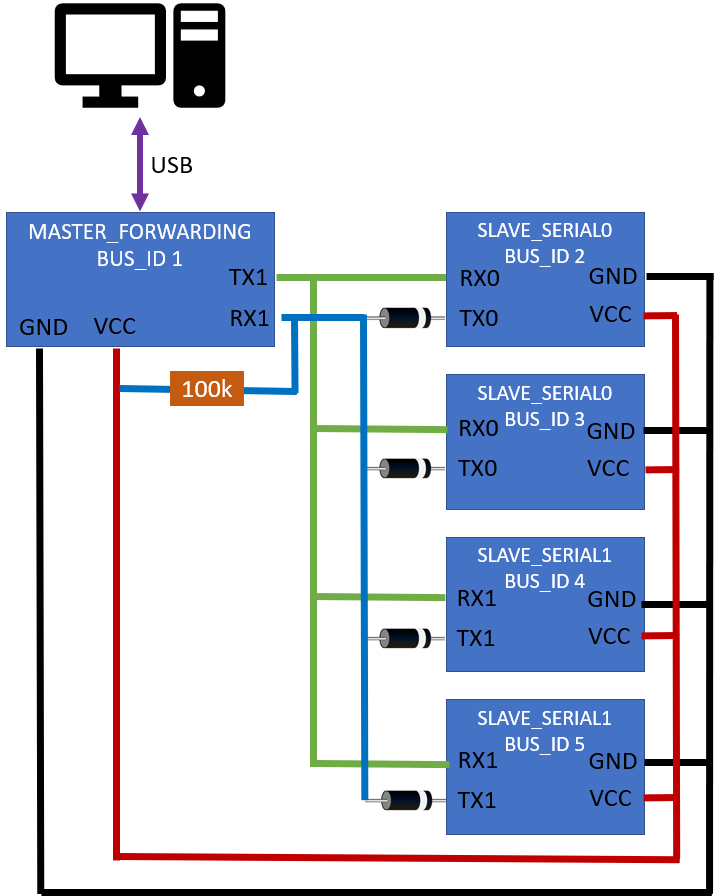
This mode configures this Arduino as a forwarder for multiple Arduinos on the serial network. This master Arduino will be connected to the PC via the USB cable. All slave Arduinos will connect to this Arduino's Serial1 port (TX1/RX1) with diodes for each Arduino.
*Disclaimer: the serial network may not work with all Arduino. You may also not mix 5v and 3.3v Arduino on the serial network.
Enable MASTER_FORWARDING if all of these conditions are met...
- this Arduino is the master with BUS_ID 1
- this Arduino has more than 1 Serial port (i.e., it has RX1/TX1 pins)
- there are other Arduinos connected to the RX1/TX1 of this master Arduino in a serial network
*Note: If you use FORWARDING mode and receive an error about Serial1 not being defined, then this Arduino does not qualify for this mode.

SLAVE_SERIAL0
This Arduino's RX0/TX0 pins are connected to a master Arduino's RX1/TX1 pins as part of the serial network.
Use SLAVE_SERIAL0 mode if all of these conditions are met...
- this Arduino is part of the serial network as a slave (it is not a master)
- this Arduino has onboard RX0/TX0 pins, and they're connected to the master Arduino's RX1/TX1 pins
- there is a diode on this Arduino's TX0 pin that is connected to the master Arduino's RX1 pin

SLAVE_SERIAL1
This Arduino's RX1/TX1 pins are connected to a master Arduino's RX1/TX1 pins as part of the serial network.
Use SLAVE_SERIAL1 mode if all of these conditions are met...
- this Arduino is part of the serial network as a slave (it is not a master)
- this Arduino has onboard RX1/TX1 pins, and they're connected to the master Arduino's RX1/TX1 pins
- there is a diode on this Arduino's TX1 pin that is connected to the master Arduino's RX1 pin
*Note: If you use SLAVE_SERIAL1 mode and receive an error about Serial1 not being defined, it means this Arduino does not meet the requirements for this mode.

Serial Network (optional)
Optionally, you can connect multiple Arduinos in a serial network to share the same USB connection. This requires the first Arduino (the master) to have two serial ports. You can recognize if the first Arduino has two serial ports by the presence of the RX1 and TX1 pins.
*Note: The firmware has documentation explaining various modes for which the Arduino can be configured.
This diagram demonstrates how multiple Arduinos can be connected to Master Arduino with a diode. Ensure the diode's band is facing the correct direction. The 100k ohm resistor is used to hold the RX1 high because the diodes prevent the slave TX lines from doing so.

Configuration

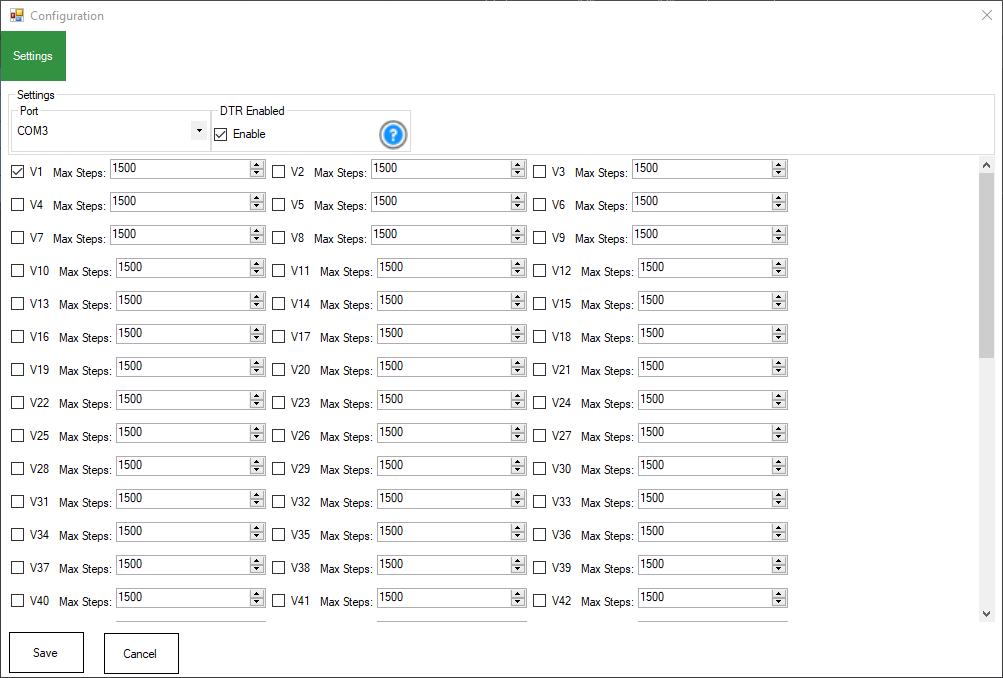
1) Port
Select the COM port for the Arduino 1 wire serial network interface.
2) DTR Enabled
Some Arduinos require this setting enabled for communication (i.e., Leonardo, Pro Micro). If your Arduino is unresponsive when querying Ping or getting a servo position, this may need to be enabled. It is enabled by default.
3) Virtual Port Selections
Put a checkbox next to each Virtual Port you wish to bind to the stepper motors. For example, BUS_ID 1 is V1. And BUS_ID 5 is V5, etc. Any commands to move the Vx port will be sent to the respective stepper motor with the matching BUS_ID. Sending a Servo.setPosition(v2, 100) will move the stepper motor with BUS_ID 2 to position 100.
Max Steps
The ARC Max servo Positions number is mapped to the Max Steps value. If the ARC Max servo Position is 180 (default), and this value is set to 1500, the stepper will move 1500 steps when a position is assigned to position 180. If the servo position is assigned to 90, there would be 750. Here is the calculation for each stepper's Max Steps setting...
Code:
stepperPosition = Map(servoPosition, arcMinServoPositions, arcMaxServoPositions, 0, maxStepperPositions)
servoPosition: The position that you specify the stepper to move into.
arcMinServoPositions: The minimum servo positions for ARC, which is always 1 and can not be changed.
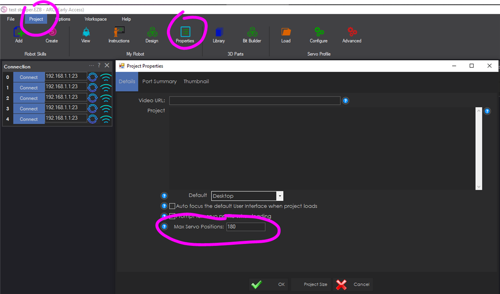
arcMaxServoPositions: The maximum servo positions configured for ARC. This value is default 180 but can be adjusted up to 2 billion per project. The configuration is in ARC Project Settings
maxStepperPositions: This is the value per stepper that determines the max number of steps this stepper can move.
That means the selected position will be scaled between 0 and Max Stepper Positions. The stepper is scaled between 0 and max stepper positions based on ARC's max servo positions.
Advanced servo Features
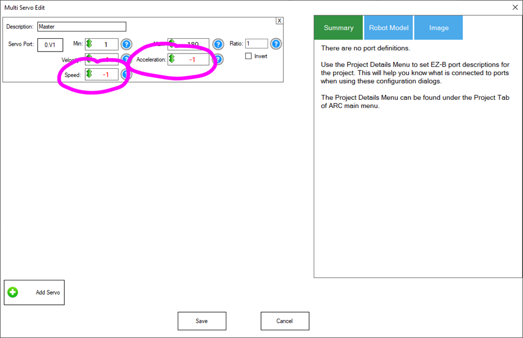
This supports the advanced options of servos for Speed and Acceleration settings. The stepper motors will speed up and slow down between their source and destination positions by configuring the acceleration option in ARC's advanced servo settings.
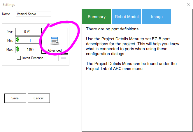
When editing a robot skill for the servo configuration, the Advanced button will allow specifying the Speed and Acceleration. You may also use the respective JavaScript, Python, and EZ-Script commands for determining the speed and acceleration programmatically.

A lower acceleration value will cause the stepper to accelerate slower as it begins to move. -1 means not changing by maintaining the current setting, and 0 means no acceleration.

Home Position
The HOME position is servo position 1 in ARC. By default, the position on power-on will be servo position 1. The ControlCommand() can specify any position to become HOME (position 1). This robot skill has a ControlCommand() for setting the HOME position to calibrate the stepper motor positions. Additionally, you can use an end-stop limit switch to calibrate the stepper into the home (position 1).
Endstop Limit Switch
This robot skill supports an optional limit switch connected to the Arduino for calibrating the position of the stepper motor. When the switch is closed to GND, that will configure the stepper to be servo position 1 in ARC. The Arduino firmware can be edited to include the option of auto-calibrating when power is applied. Otherwise, you can programmatically enable calibration with the control command.
Place a limit switch on the lowest position of the lever connected to the stepper motor. This switch will be used as the limit switch if configured. When calibrating, the stepper will move toward the lowest position until the limit switch is reached. Once the limit switch is reached, that will be position 1 in ARC until the power is cycled. There is no memory of the position between power cycles.
Ensure the calibration rotates your stepper in the correct direction, which will be position 1 in ARC. You may need to specify the INVERT option in the firmware if the stepper rotates in the wrong direction. The limit switch should always be at the lowest position for the stepper, which means position 1 in ARC.
Increase servo Resolution
ARC has a project-wide setting for increasing the servo resolution across all robot skills. Increasing this value will give the stepper a high resolution supported by your stepper motor.

Test Bi-direction Communication
This allows the Arduino to report the current position of the stepper during movement using the script command GetPositionRealtime(). This command will retrieve the real-time position of the stepper from the respective Arduino. The Arduino's are responsible for moving the stepper, including acceleration and speed.
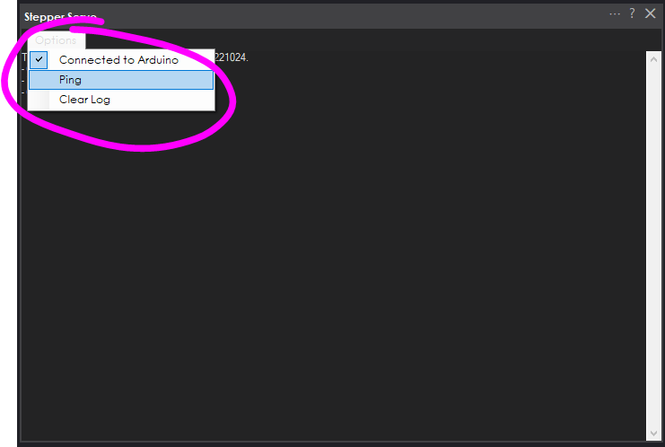
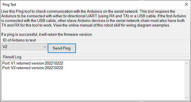
The robot skill main screen has a Ping menu option to test bi-direction communication.

When the ping option is selected, a new window will open with options to ping the Arduinos and view their firmware version. Here you can choose the port for each Arduino on the serial network to verify communication and the version number.

Arduino Firmware
The Arduino code must be downloaded from here and programmed onto each Arduino. The recommended Arduino for this usage would be small and affordable, such as a Pro Micro, Micro, Nano, or ATTiny. These are all very low-cost devices that are small and do not take up much space.
1) Download Arduino Firmware from here: Stepper_Servo (Version 20230223).zip (Updated Feb 23, 2023)
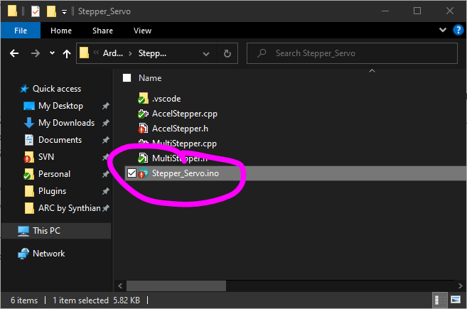
2) Uncompress the firmware to a folder and open the INO file with the Arduino editor

3) Configure the BUS_ID on the one-wire serial network in the Arduino editor for this instance. It can be a number between 1 and 127. This number will correspond with the respective Virtual servo Port in ARC. Each Arduino/Stepper will have a unique ID.

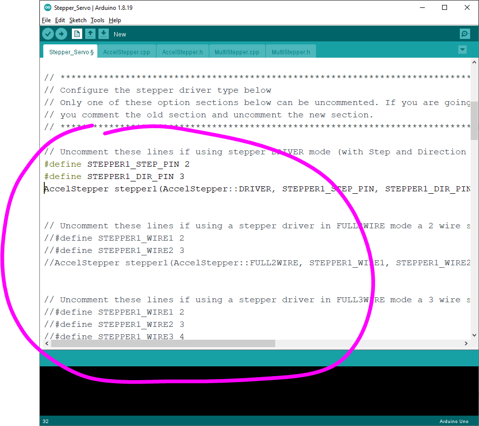
4) In the Arduino editor, configure the type of stepper driver that you will have connected to the Arduino. There are multiple types of stepper drivers to be supported, including two-wires, three-wire, four wires, etc. Uncomment the section of the kind you will use with this Arduino. Only one area can be uncommented at a time, so comment out another section if editing a previous configuration.

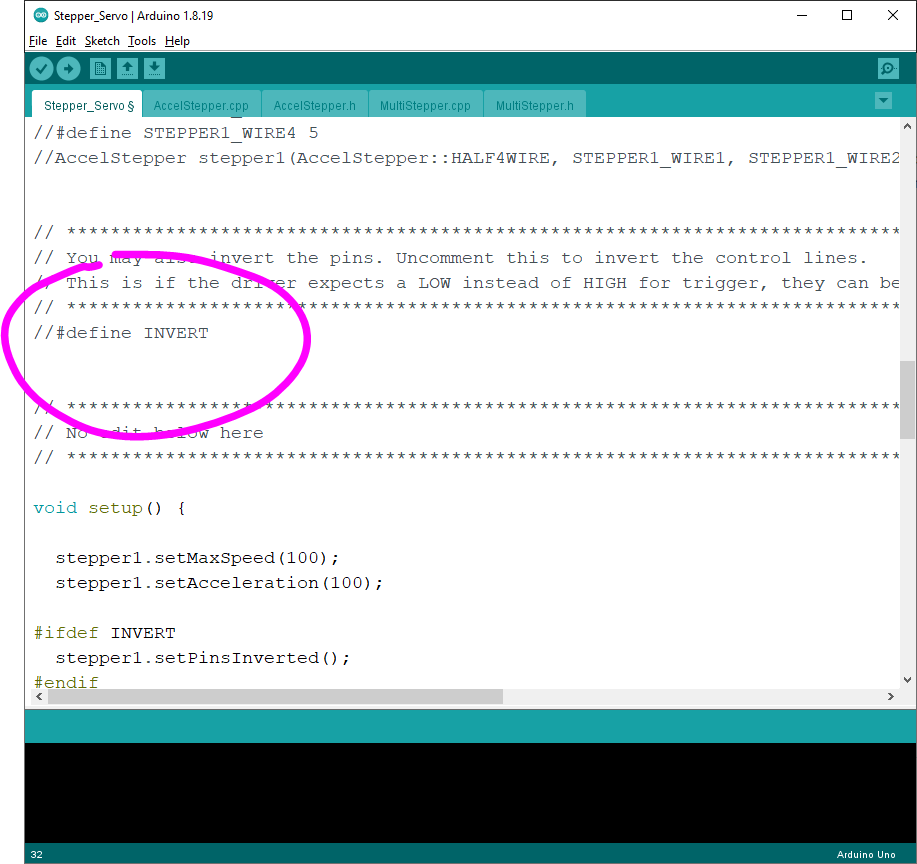
5) In the Arduino editor, you can configure control line wires from the Arduino to the Stepper Driver if they need to be inverted. This is only if the stepper driver requires an inverted GPIO so that HIGH becomes LOW and vice versa.

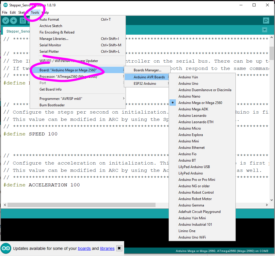
6) Ensure you have selected the correct Arduino Board that you are using

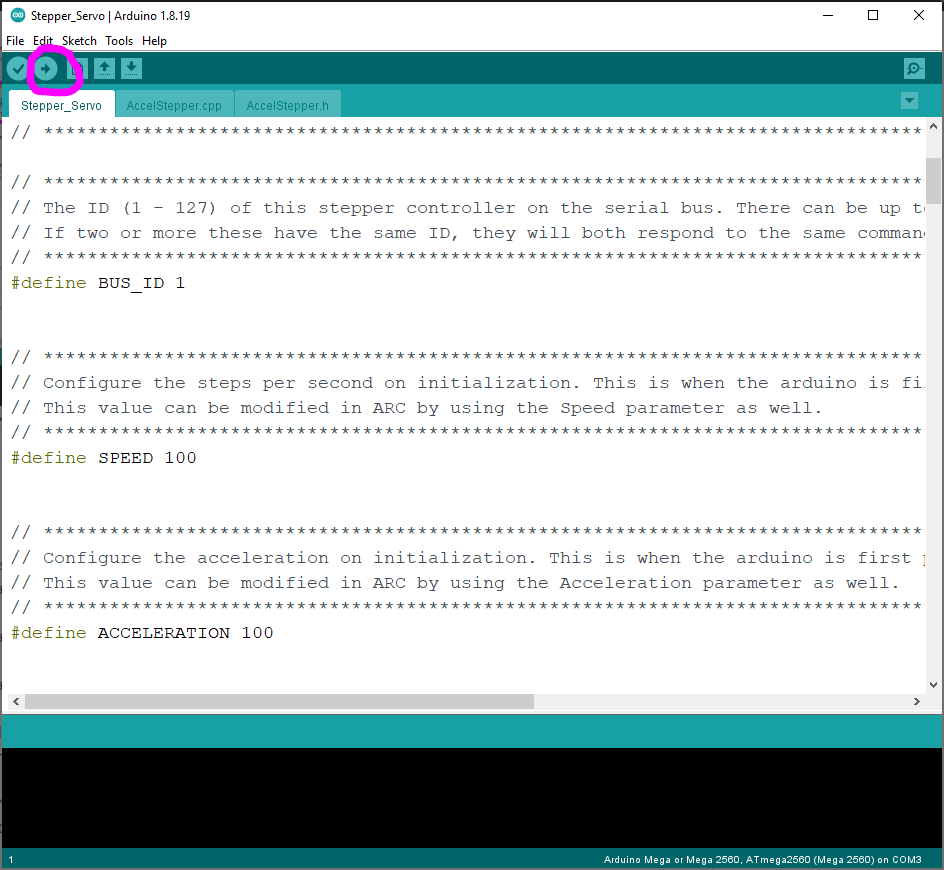
7) Program the Arduino with the edited code.

Troubleshooting
- Ensure you have the latest Arduino firmware installed on your Arduino(s)
- Ensure you have the latest Stepper servo robot skill installed in ARC
- Ensure you have the latest ARC installed (Early Access edition is recommended)
- The stepper driver needs to be connected to the Arduino I/O pins. Ensure the pins are connected and specified in the Arduino firmware. Ensure you uncommented the correct stepper driver type in the Arduino firmware before uploading it to the Arduino.
- A common GND is necessary across all electronic devices. Ensure the stepper motor driver, stepper motor, Arduino, and PC have a common ground. The Arduino will be grounded to the PC if connected via a USB cable.
- The configured BUS_ID on the Arduino must match the selected checkboxes in the Robot Skill's configuration screen
Remember, the BUS_ID will match ARC's Virtual servo (Vx) ports. So BUS_ID 1 will match V1 in ARC. BUS_ID 2 will match V2 in ARC, and so on...
I will try it out
your Arduino firmware works, connects on my com port 11
when I uploaded new Accelstepper ino to Arduino, then try to connect on ARC, so far, com11 can't connect
My Arduino, I use 57600 to run your Arduino firmware software
I tried all the baud rates
Can't figure it out what can be the reason
any Ideas?
What do you mean by that?
#define _BAUD_RATE 57600
When I go to the COMUBS connection
- new firmware
- fix for acceleration
- tested on arduino without stepper motor. The steps for positioning is most likely WAY off and needs to be adjusted. I'll do that next week when i get a stepper motor to test with.
- Lowered the resolution so it spins more like a servo without gearing. I'll have to add an option to adjust the gearing values later when I get a stepper motor to test with. Right now I'm testing with LEDs on an Arduino lol
so far I read that, I added Stepper Servo, says connected to com11
- updated with a new arduino firmware
- allows specifying the max positions for the stepper to rotate (read manual above)
- tested and confirmed to work great
Thanks DJ!
the one trouble I ran into was the wiring for the hbridge. There wasn’t a clear example of what order to connect the pins for the driver to arduino. I gather it has something to do with the way the coils are connected in the motor, but not sure on how to identify the order.
If someone with more stepper experience knows, maybe they’ll chime in. But I ended up trying a few combinations until I got it working. For a while the stepper would only go one direction and never reverse.
saw this on another code site
// Create Instance of Stepper Class
// Specify Pins used for motor coils
// The pins used are 8,9,10,11
// Connected to L298N Motor Driver In1, In2, In3, In4
// Pins entered in sequence 1-2-3-4 for proper step sequencing
Code:
any regular servo control will work. If your stepper is moving only in one direction, it’s the wiring or arduino ports misconfigured. You’ll have to read what I wrote above about that. Meaning, you have to know your configuration and stepper motor wiring. Theres nothing I can directly help with because there’s a million possible configurations and types.
Thanks,
A unipolar stepper will usually have 5 or 6 wires and are a bit harder to figure out the wiring because they have center taps coming off the coils. The center tap wire will be half the resistance of the full coil. You can treat unipolar steppers like bipolar steppers by ignoring the center tap wires.
I raised the #define ACCELERATION 100 to 200, it spins better
My other Arduino has different code for a Bipolar Stepper, NEMA 17 with L298N H-Bridge starting with #include <Stepper.h> not AccelStepper.h
STEPPERONLINE CNC Digital Stepper Motor Driver 2.4-7.2A 18-80VAC or 36-110VDC for Nema 34 and 42 Motor on Amazon. I will do some experiments and get it working with an EZ-B. It will take 4 wires though, pulse direction, enable and ground. A simple way is to send out a steady stream of pulses and a more involved way is to have the pulses go up exponentially for acceleration, deceleration. This could be done with algebraic expressions in blockly. I wouldn't mind being a part of the one selling that skill.
Yeah, the driver you are referring to seems straightforward. You may not be able to get high speeds from it but simple operation with Blockly (or other) scripting seems reasonable enough.
both the Bipolar Stepper, NEMA 17 with L298N H-Bridge and the 28BYJ-48 Unipolar Stepper with ULN2003 motor driver
the wiring - "step sequence" in the code was the problem at first
- updated the robot skill and firmware
- the firmware update is required if you wish to use the end stop limit switch calibration
The optional end stop limit switch calibration is documented in the manual above and within the Arduino firmware file. The end stop limit switch allows the stepper to rotate toward a direction until a limit switch is reached. This will set the stepper to servo position 1 in ARC.
The end stop limit switch calibration can be configured to execute after power-on automatically or programmatically using the ARC controlcommand.
Maybe you have ARC loaded at the same time when trying to program the ardunio. You can’t have both running.
close ARC and then program the ardunio. Once the arduino is programmed, you can load ARC again.
which uses pulse and direction. I only uncommented the 3 lines for stepper driver mode for step and direction and it doesn't compile. It is not hooked up to the EZ B-will do it after it uploads. Tried different things after that and still couldn't get it to work. Any suggestions?
Would this be the correct way to wire this for the DRV8825 and use this skill? If so what section would you uncomment?
This would be for an A4988
When using an encoder for feedback, there is no way for it or the software to know where Home is after the power is cycled. You need to send the Home command to the motor controller. Then the motor will seek the one end point. It will count pulses as it travels and use that info to determine position Once it finds one end of travel it knows where home is.
When using a potentiometer the controller will know right away where the motor is positioned within the travel space. This is because it is reading voltage and uses math to figure out how far away it is from the end points. From this voltage reading it knows where the end points are.
Again, I don't know this skill but it should be able to use the above info somehow in setting up the start position of the motor.
How is this skill getting feedback from the stepper motor?
Once the limit switch is reached during the auto or manual calibration, that becomes position 1 (one) in ARC.
There is no "memory" for the position in an Arduino because they don't have a memory. So you can decide if you want to calibrate every time the robot is powered on, or you can manually specify it to calibrate with the control command.
You will find this information in the above manual under the "Limit Switch" section.
Error when compiling after doing the below setting up for DRV8825 drivers with step and dir connections. I get and saying there is no STEPPER1_WIRE1 defined. If I uncomment the the FULL4WIRE section it works but that does not match the connection picture in the manual above. What would be the way to set this up and connect it to the Arduino?
Gives the follow error seen below
Would this be the correct way to wire this for the DRV8825 and use this skill? If so what section would you uncomment?
The section that you're uncommenting looks correct for the DRV8825
Arduinos have USB connections for programming. When the Arduino's USB is connected to the PC, it will become a COM port. With this configuration, you only require one Arduino connected to the PC via USB, and all other Arduinos will connect their RX0 pin to the first Arduino's RX0 pin. All Arduino's on the one-wire serial network will have their RX0 and GND pins connected. They all receive the same packets with this configuration, but they will only process the packets that match their unique BUS_ID.
I would think it should read like this "first Arduino TX pin".
Arduinos have USB connections for programming. When the Arduino's USB is connected to the PC, it will become a COM port. With this configuration, you only require one Arduino connected to the PC via USB, and all other Arduinos will connect their RX0 pin to the first Arduino's TX pin. All Arduino's on the one-wire serial network will have their RX0 and GND pins connected. They all receive the same packets with this configuration, but they will only process the packets that match their unique BUS_ID.
The FIRST arduino's TX is connected to the other arduino's RX. So the TX of the first arduino transmits to the RX of all other arduinos. Your original notice was correct
Getting closer but not quite there.
I think the section in the code that needs to be uncommented would be something other than the step/dir section. Maybe someone else can chime in. Note DC source of 5V is needed for the Ardino.
Arduinos have USB connections for programming. When the Arduino's USB is connected to the PC, it will become a COM port. With this configuration, you only require one Arduino connected to the PC via USB, and all other Arduinos will connect their RX0 pin to the first Arduino's TX0 pin. Remember, all Arduinos also need to have their GND pins connected. All Arduino will receive the same packets with this configuration, but they will only process the packets that match their unique BUS_ID.
A great site to understand steppers is https://dronebotworkshop.com/stepper-motors-with-arduino/
you said on your other page:
Quote:
https://dronebotworkshop.com/stepper-motor-hall-effect/
there is other stepper motors info there on the site
The step sequences were my problems, but I resolved it
I did get them moving forward and reverse
All you have to do is uncomment the stepper driver mode option in the Arduino firmware...
Code:
This is because the schematic you posted above demonstrates that you only need to use the STEP and DIR from the Arduino to the controller's input. If the DIR is not working, the four wires to the stepper must be misconnected.
I was using a pulse generator in active low to rotate the stepper motor and that was rotating fine so the wiring to the motor is one less variable that could be wrong. Which pins from micro should be to the driver? Is the micro different from the Uno in that it has to be active low but the Uno can be both active high and active low?
The resolution index is not really resolution (which it has plenty of). It is more in line with amount of rotation, as you change this amount it is changing degrees of rotation. How many actual pulses is it putting out per degree?
If we know this amount then we will know how far it will rotate. Where in the code is this located? This one would also be nice to have as a global variable.
Thanks again,
Don
your other questions regarding the step values are settings in the firmware file.
A common GND is necessary across all electronic devices. Ensure the stepper motor driver, stepper motor, Arduino, and PC have a common ground. The Arduino will be grounded to the PC if connected via a USB cable.
In my build I have a 6V 60A DC power supply and for the my 5V devices I have a 5V buck converter that powers my Lattepanda and also the powered USB hub that is connected to the Lattepanda. To power the planned stepper motors I will be connecting a 12V boost converter to the 6V power supply. So here's my question. If the first Arduino BUS1 is connected with a USB from the USB hub connected to the Lattepanda for BUS2 Arduino where does the power need to come from? The same 5V buck converter the hub and the Lattepanda is connected to?
Because all the power in being supplied by the 6V power supply would all the grounds be considered common? Meaning the 12V Boost and the 5V Buck grounds and the power supplies ground are common?
I was planning to power the Arduino's with 5V mini buck converters on each motor being powered by the 12V feed from the 12V boost converter. This all depends on determining a common ground based on the statement above.
A potentiometer is the easiest solution, as it would connect to an EZB ADC port. The ADC value can then be used as a position. This can be combined with an existing ADC robot skill available here: https://synthiam.com/Support/Skills/Servo/PWM-Servo-Feedback-ADC?id=18047
i looked into it and I agree it is possible. It’ll operate the same as the robot skill I shared above.
we’re gonna look into it further and see what we can do. Stay tuned
Most advanced robots would have the servo range increased for higher resolution. Read more about ARC servo resolution and how to configure it in the servo manual here: https://synthiam.com/Support/ARC-Overview/Servo-Controls
- Includes support for a bi-directional connection method that allows querying the stepper positions during movement. See the manual above for wiring
- Additional debugging messages added
- Requires updated firmware for October 5th, 2022 or newer
Don
For the limit switch it states that it is port 6, is that an adc port- is that on the Arduino or on the EZ?
watch and read this
https://dronebotworkshop.com/big-stepper-motors/
I have to go now, see you in a few days for you progress
Thanks
I’ll make a quick update to the robot skill tomorrow that allows testing with a ping. That way you can see if the arduino is correctly connected
It states that port V1 is unresponsive I have confirmed that the stepper panel and the stepper servo panel are both on V1 I am using the Arduino Uno what would cause it to be unresponsive? Have confirmed that other small servos are working OK also have confirmed that it is using port six in the stepper servo panel
I’m guessing you either have the wrong com port selected or you’re not uploading the firmware to the ardunio successfully. There’s instructions above for both
I tested a Bipolar Stepper, NEMA 17 with L298N H-Bridge with an Arduino with DJ's code
in code using 8, 9, 10, 11 for pins 1,2,3,4,
external 12 v power supply for stepper motor
all grounded together, the 12v and the Arduino - used a small bread board, EnA EnB to bread board 5v form Arduino
used in the code - #define ACCELERATION 300 - spins better - will try a higher ACCELERATION later
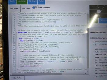
It was mentioned earlier that it is impossible to have a variable because it is a separate piece of hardware. You can use functions like a variable. A function returns a value. Use the function to get the position instead of using a variable.
Combine this robot skill with one of the servo position robot skills that does just that. It was mentioned above as well.
PWM servo feedback (ADC): https://synthiam.com/Support/Skills/Servo/PWM-Servo-Feedback-ADC?id=18047
PWM servo feedback (I2c): https://synthiam.com/Support/Skills/Servo/PWM-Servo-Feedback-i2c?id=18069
I tested a Bipolar Stepper, NEMA 17 with L298N H-Bridge with an Arduino with DJ's code
In the code I used 8, 9, 10, 11 for pins 1,2,3,4,
external 12v power supply for stepper motor
all grounded together, the 12v and the Arduino - used a small bread board, EnA EnB to bread board 5v form Arduino
used in the code - #define ACCELERATION 300 - spins better - will try a higher ACCELERATION later
The ping worked, you can see above
What was your mistake at first?
EzAng
So instead of using a variable, use that function block. That block returns the position of the stepper where it is. You can read more about that block by selecting HELP on that block.
This thread is about questions regarding the stepper robot skill. If you have programming questions, you'll need to create another thread so we can keep the website organized for other users, please.
Have three different steppers working individually with different com ports but when I tried to get them all hooked with one as main com port sending out via Tx to the next 2 receiving via Rx and tied all the grounds together but it did not work. I made the Tx line put out 2 parallel wires just like the picture and also put a check in V1, V2, V3 checkboxes in the stepper panel. Tried to ping the other 2 and they were unresponsive. Don't they need to ping to work properly and don't they need both the Rx and Tx to make them ping?
settings as follows:
#define BUS_ID 1
#define SPEED 100
#define ACCELERATION 100
#define CALIBRATE_ON_POWER 1
#define CALIBRATION_DIRECTION 0
#define CALIBRATION_STEPS 50
#define END_STOP_LIMIT_PORT 0
// Uncomment the four lines below if using stepper DRIVER mode (with Step and Direction pins).
#define STEPPER_TYPE DRIVER
#define STEPPER1_STEP_PIN 1
#define STEPPER1_DIR_PIN 2
AccelStepper stepper1(AccelStepper::DRIVER, STEPPER1_STEP_PIN, STEPPER1_DIR_PIN);
USB is connected to the Seeed Studio XIAO and the driver is connected to a 24V DC supply.
At power up the stepper motor searches for home and when the hall sensor is triggered it stops. So far so good... But now when I try the Vertical servo set to a virtual 0.V1 port I get no movement. I know I must be doing something wrong. Can anyone please help me figure this out. Note: my ARC is not connected to any other device.
It is basically wired like this:
The UNO would be the Seeed Studio XIAO
#define END_STOP_LIMIT_PORT 0
#define STEPPER1_STEP_PIN 1
#define STEPPER1_DIR_PIN 2
Seeed Studio XIAO PIN OUTS
Should ARC be connected to the SEEED on com3. also to be able to test this? If so it will not connect.
I got it working again as I stated above - forward, and reverse - works well
single stepper setup
I tested a Bipolar Stepper, NEMA 17 with L298N H-Bridge with an Arduino with DJ's code
when setting things up for this stepper stuff it looks like the stepper skill is connecting to the com port the Seeed (arduino) is on. But do I also need to have a connection to the Seeed on the connection panel also?
I have not been able to find anything that spells it out clearly to me yet.
I see in your picture it looks like your arduino is connected to your pc. Do you have that USB com port connected in the board connection panel?
Also, the firmware now has the max step positions and more information on what the setting for "SPEED" means.
I don't seem to have this issue with and Arduino UNO using the same skill.
Added more debug information to help people get this skill working.
just connect to the stepper skill for the Arduino - I used com5
no connection is needed in the connection panel
smiller29, hope this helps you today
IOTinys and regular servos are different, don't need the stepper skill
My Arduino is connected to ARC with the stepper skill by the USB wire
your Seeed Studio XIAO PIN OUTS - looks about the same as my Arduino
On ARC under project, properties, I am using - Max servo positions - 1024 for better smooth movements
Also can you try going from highest to lowest and see if it works for some reason mine is not moving properly if I go from 90 to 180 it is fine or 90 to 1 it is fine I have updated the two new pieces of software this morning before I got started
If now have a few questions I hope you can help with because I am not sure where to start. I am attaching the stepper motor to a gearbox with a 38:1 ratio for a full 360 degree rotation. My goal is to have this gearbox move from 1 to 225 degrees as fast as I can using this skill. My questions is how do I go about figuring out what the settings should be in ARC and this skill?
The stepper is set for full steps. My understanding a NEMA 17 make 200 full steps to go a full rotation. So am I understanding that to turn this gearbox 360 degrees it 38 x 200 = 7600 steps? making every 90 degrees of the gearbox would equal 1900 steps of the motor?
So to make the gearbox rotate 225 degrees the stepper needs to move 4750 steps?
MAX_STEPS_FOR_ARC_POSITION 4750
also what is the max value that can be defined for MAX_SPEED?
Sorry if these seem like dumb questions but I am new to all this stuff.
MAX_STEPS_FOR_ARC_POSITION 4750 is what it is set to and when I move the servo control it does not even come close to rotating 225 degrees maybe about 20 degree at best... also the motor does not seem to be moving as fast as it should it also sometimes jerks or stutters as it speeds up and slows down.
I have set the global ARC servo resolution to 270.
also what is the max value that can be defined for MAX_SPEED? I have it set to 500 like you have it. I am using a 24V supply for the motor.
Oh one more thing do you have a servo control like a slide bar because the controls are hard to use with a touch pad. I am sure with a mouse wheel they are easy to use but I don't use a mouse. I have used the touch pad skill also but that also is hard to use. slider controls would be the best solution.
1) Put your max speed back to something normal (not 500)
2) dial in your MAX_STEPS_FOR_ARC_POSITION so you get what you want
3) dial in your speed. If you make the speed to fast of a number, you'll miss steps and exprience what you have now.
You can check to ensure the stepper is connected to the driver correctly. Maybe it's only moving partial because one of the coils is connected backward.
#define MAX_STEPS_FOR_ARC_POSITION 1500
#define ACCELERATION 200
#define MAX_SPEED 200
works fine forward and reverse
I use these
https://www.amazon.com/ELEGOO-Board-ATmega328P-ATMEGA16U2-Compliant/dp/B01EWOE0UU/ref=sxts_rp_s_1_0?content-id=amzn1.sym.acfa156f-6066-4c30-8587-c628ec07e337%3Aamzn1.sym.acfa156f-6066-4c30-8587-c628ec07e337&crid=1M1ITNLIB6NDK&cv_ct_cx=Arduino&keywords=Arduino&pd_rd_i=B01EWOE0UU&pd_rd_r=86b6ca4c-ce52-43c0-a94b-01a5990f9888&pd_rd_w=fdzA5&pd_rd_wg=yyip8&pf_rd_p=acfa156f-6066-4c30-8587-c628ec07e337&pf_rd_r=VNRQ259RR4JFSF176MV9&psc=1&qid=1666020557&qu=eyJxc2MiOiI2LjAwIiwicXNhIjoiNS4yMSIsInFzcCI6IjUuMDMifQ%3D%3D&sprefix=arduino%2Caps%2C549&sr=1-1-f0029781-b79b-4b60-9cb0-eeda4dea34d6
This pack will slide in and out of a holder so they can be updated and serviced easily.
Seeed Studio XIAO SAMD21The Smallest Arduino Microcontroller Based on SAMD21,with Rich Interfaces, 100% Arduino IDE Compatible, desiged for Projects Need Arduino Micro, 1pc
https://www.amazon.com/dp/B08CN5YSQF?ref=ppx_yo2ov_dt_b_product_details&th=1
Is there any way to get a skill with sliders bars with Min <------------------------> MAX ?
@EzAng, can you do me a test please set MAX_STEPS_FOR_ARC_POSITION to 5000 and try it please.
Here is the results smiller29,
I uploaded to the Arduino code - MAX_STEPS_FOR_ARC_POSITION to 5000
As you can see below, I used On ARC under project, properties, I am using - Max servo positions - 5000
It works fine, forward and reverse - I suspect it going to the 5000 position then it stops - "horizonal servo skill" maybe what you want - you can stop this in any position if you desire, every 20 or whatever...
my "continuous servo" skill stops also after a while = again maybe it going to the 5000 position
1) the min pulse width is too low for your driver board
2) the stepper isn’t getting enough power and missing steps
3) the speed value is too fast for the Arduino (doubtful if it’s less than 3000)
4) one of the stepper coils is connected to the driver backward (or not at all)
You see, the get position real-time command will show the stepper's current position based on the number of steps sent. So if your stepper is off, you can view the get position in real-time and see that it thinks it’s in the correct place. That’s because it did send the steps, whether or not they were received or processed.
Unfortunately, the issue is at your end. You’ll have to read the suggestions I wrote in this post and test to find what’s causing your behavior. I don’t think there is any additional debugging information I can add to assist with the missing stepper steps.
So I want to thank everyone for helping me out.
The sad thing is I need to come up with a better gear ratio because 38:1 is to slow using a stepper motor.
Is it correct to load the Arduino code with #define BUS_ID 2 on the second Arduino? and Horizontal servo add V2 servo
is this correct?
read all instruction, tried many scenarios
thanks, in advance
Automation Man, something is wrong, I tried so many connections and altering of code etc...
we need :
step 1
step 2
step3
and so on...
the issue is that some arduinos have an onchip usb interface, and the rx/tx of pins 0 and 1 are for serial1. While other arduinos have a second chip to interface with usb and their rx/tx of pins 0 and 1 are for serial0
I’ll have to modify the firmware so they can communicate over serial0. And so the first arduino will need to relay all serial data from serial0 to serial1
There's a new configuration section specifying the operating mode in the firmware. The modes are documented in the firmware comments.
and for the second Uno R3 I uncommented Uart mode serial1 and it also mentioned serial one was not declared in the scope
was I supposed to uncomment anything else relating to the modes? I uncommented only one at a time as usual.
the second Arduino is not receiving any data, can't figure this out
first Arduino is in TX
second Arduino RX
Everything is hooked up and lit up
any advice?
tried:
#define UART_MODE FORWARDING
#define UART_MODE SERIAL0
and just
#define UART_MODE SERIAL0
Port: V2 unresponsive! (The operation has timed out.)
I just got the v2 to connect and my moter drive went out
I believe we all need a tutorial video on this one, like others we had.
no one has succeeded on this skill
I just got the v2 to connect, then my motor driver went out, have to wait to I get home, at my farm doing all this now.
tried 3 Arduino to see if the second one would connect, nothing ...
The below is sample code for connecting to a Raspberry PI
Code:
Suppose this documentation mentions pin 0/1 for serial1 or serial 0; that is the default for Arduino. If your aftermarket Arduino uses different pins for serial1 or serial0, it's still the same serial port. You can do that research by reading the documentation for your product to know what pins Serial0 or Serial1 are for your Arduino.
I see people using random settings and posting about them. Uncommenting multiple lines when the instructions mention one line. Or trying things like DTR when the documentation says it has nothing to do with multiple Arduinos on the serial network. It all comes down to not reading the documentation. We can fix bugs, but the best we can do to have your unique configurations work is by writing documentation in the firmware for you to read.
I wish there were an easier way to configure the Arduino for this to be a more straightforward process. But the most I can do is provide links and documentation because we’re covering a HUGE variety of devices with this solution.
There are thousands of Arduino, including aftermarket versions. There are thousands of stepper drivers, each with different electrical connections. And thousands of stepper motors. Plus, different power setups and other unique project configurations make this a difficult robot skill to make easy, as Synthiam does. With these hardware options, we’re trying to cover everything.
The proposed solution at our dev meeting was to standardize one Arduino model, one driver, and one stepper type. That way, there’s no configuration necessary, and it’ll just work. But that doesn’t mean it’ll work with your existing hardware.
I took over the development of this robot skill to keep it modular. It’s because this solution tackles such a wide variety of devices instead of one standard configuration.
So in FORWARDING mode Serial is the incoming data on the USB cable and Serial1 is the Arduino TX and RX to the slaves.
MASTER = FORWARDING
SLAVES = SERIAL1 or SERIAL0
I can't seem to locate more detail on function readBlocking() can you provide more insight as to what this is doing? I think I know but not sure.
1) Connect the usb arduino tx to the slave arduino’s rx.
2) connect the usb arduino rx to the slave ardunio’s tx
And ensure you’re using the correct mode that matches your configuration by reading the documentation in the firmware.
1) ensure the correct mode is configured for each ardunio
2) wire the serial network correctly
Arduino #1
- Mega
- Configured for Forwarding mode
- Connected to PC via USB (Serial0)
Arduino #2
- Leonardo
- Connected to the Arduino #1 (Mega) through the Leonardo's TX1/RX1 pins to the Mega's RX1/TX1 pins
- Configured for Serial1 mode (because Serial0 is the USB)
See, it works...
A million combinations are based on the various hardware, but I test with all. The Mega is a good test for Arduino #0 because it can work in either Forward or Serial0 modes.
Preview the firmware file and review the documentation to ensure you have chosen the correct mode...
Master Arduino
On the first Arduino, you should use forwarding mode if you have the RX1/TX1 pins.
Slave Arduinos
On slave devices, if you have RX0/TX0 pins, then use SERIAL0 mode. If you have RX1/TX1 pins, then use SERIAL1 mode.
Also, because Arduino is a free-for-all with no standard, there is some device with 5v I/O and others with 3.3v I/O. That may cause an issue with a serial network because the 5v I/O will be much stronger. In that case, try to use Forwarding mode on the first Arduino and stick with 3.3v Arduino as slave devices.
- I added an option in the firmware file for debugging LED. There's a description written for the option; you'll need to read to see if you can use the option.
// SERIAL0
// -------
// This option will use the first serial port (Serial0) for all communication. Generally, this is used for Arduino's that have
// on onboard serial driver chips. This means the first serial port (Serial0) can be used for both USB communication and the
// serial network.
//
// Use SERIAL0 mode if all of these conditions are met...
// * this Arduino has onboard RX0/TX0 pins
#define UART_MODE FORWARDING does not compile by it self
#define UART_MODE SERIAL0 compiles
#define UART_MODE SERIAL1 does not compile by it self
using SERIAL0 mode - compiles
using Arduino Unos
Arduino 1 - TX 1 #define BUS_ID 1 ---- v1 servo move forward and reverse
Arduino 2 - RX 0 #define BUS_ID 2 --- v2 nothing
Ping:
Port: V1 returned version 202210222
Port: V2 unresponsive! (The operation has timed out.)
I see my Arduinos are not the correct ones, I need a Arduino Mega
Forwarding mode does not compile here
here is what happens:
says
'Serial1' was not declared in this scope
and Serial1 mode says the says thing when I try to compile it
only ones that compile is UART_MODE SERIAL0 and UART_MODE Forwarding
or just UART_MODE SERIAL0 compiles
I don't know what else to tell you. I can't keep repeating "read the documentation" because it isn't helping. You can't use someone else's configuration for their hardware and expect it to work with yours.
On top of that, there are things I can't help you with because they're electrical - such as, are you mixing 5v and 3v Arduino? Are the Arduino's official or knock-offs? Are the UARTS holding the TX high with too much current, and the transmitting Arduino can't pull it down? Maybe you need diode's on the TX line? Anyone diving into using a complete custom hardware solution must learn to address those questions because there is no possible way a custom hardware solution can be modularized for a million possible combinations.
The robot skill works. Your hardware configuration, Arduino selection, or electrical doesn't work.
Here's what I'm going to do tomorrow. I will modify this robot skill to work with a specific hardware requirement for the Arduinos. It won't be as modular to support all hardware because that isn't working for the three people on this thread who can't figure it out. So once I standardize the robot skill for specific hardware, it will work, but you'll need that hardware. That's the best solution to put this to rest.
1) master arduino must have a usb and serial1. No exceptions. If your master ardunio doesn’t have a serial0 and serial1, it won’t work at all as master.
2) the slave arduinos on the serial line will need a diode on every TX pin. Without the diode, it most likely won’t work for your hardware. So you’ll need a diode for every slave arduino on the serial network.
There are too many variables causing issues with the current open configuration. We will simplify the hardware by limiting the requirements. This way, it will work for everyone with the correct hardware.
I am not known as a quitter, but maybe enough time has been spent on this one,
thanks for all your help and thoughts
Time to sit back and see what Automation Man, SMiller29 and others come up with.
1) master arduino must have a usb and serial1. No exceptions. If your master ardunio doesn’t have a serial0 and serial1, it won’t work at all as master.
It is advised to read the documentation provided in the firmware file for configuring the Arduino to its appropriate mode. The schematic for connecting slave Arduinos with the required diode is posted in the manual above.
will test on Thursday
Automation Man, did you try this yet with a diode yet?
thanks DJ, for all your help and time
In the future, you can find information about a command by right-clicking and selecting HELP in Blockly (which we notice you prefer).
This command was added in a previous release of ARC. You can find the release notes here: https://synthiam.com/Products/ARC/Releases
The specific release note for this update can be found here to ensure you’re using the latest software: https://synthiam.com/Products/ARC/Releases/ARC-2022-10-08-00-Early-Access-Runtime-21335
5W 12V Power Zener Diodes ?
Chanzon 1W Zener Diode Assorted Kit (30 Values x 10pc 3V 3.3V 3.6V 3.9V 4.3V 4.7V 5.1V 5.6V 6.2V 6.8V 7.5V 8.2V 9.1V 10V 11V 12V 13V 15V 16V 18V 20V 22V 24V 27V 30V 33V 36V 39V 43V 47V) Assortment Set
is this ok?
why so large?
(100 Pcs) 1N4004 Rectifier Diode 1A 400V Hole DO-41
sure?
https://www.amazon.com/gp/product/B07Q4F3Y5W/ref=ox_sc_act_title_3?smid=A2RFXKS6GNXFWP&psc=1
So I ordered from Amazon:
Chanzon 1W Zener Diode Assorted Kit (30 Values x 10pc 3V 3.3V 3.6V 3.9V 4.3V 4.7V 5.1V 5.6V 6.2V 6.8V 7.5V 8.2V 9.1V 10V 11V 12V 13V 15V 16V 18V 20V 22V 24V 27V 30V 33V 36V 39V 43V 47V) Assortment Set - coming Friday
Is a switching diode approiate for this circuit? From what I read a diode conducts in one direction only (uni-directional only in forward biased conditions). Zener diode is bi-directional (it conducts both in forward biased and reverse biased conditions).
Disclaimer: I'm not an electronics expert. Perhaps a switching diode will work but will it operate properly in this circuit? I would assume it will work if you place the band in the proper orientation.
I'm not sure what the intention of the diode in this circuit is. I assumed it was simply to block any voltage or signal backfeed. I would think a simple 1N4001 through 1N4004 (rectifier diode) would work nicely. Remember we can over size but not under size. Are you guys simply wanting a very small sized diode to fit better?
My conclusion is that both types will work. Another option would be a Schottky diode. They are quite remarkable in a lot of ways and are a super replacement for the common 1N400x diodes.
One last thought. From what I read: in a small silicon diode operating at its rated currents, voltage drop is about 0.6 to 0.7 volts. The value is different for other diode typesSchottky diodes can be rated as low as 0.2 V, germanium diodes 0.25 to 0.3 V, and red or blue light-emitting diodes (LEDs) can have values of 1.4 V and 4.0 V respectively. If using as a simple blocking diode then voltage drop is not an issue.
Thanks,
Don
I haven't used this skill but looking through the instructions, can't you already set the speed (and acceleration) under the "Advanced servo Features"?
The driver uses a signed long variable type. Long variables store 32 bits (4 bytes), from -2,147,483,648 to 2,147,483,647
so even if the code were to be modified for some type of lengthy rotation, you’d have a maximum number of steps per direction anyway.
Why would you want to use a stepper motor for continuous rotation? That’s what regular brushed or brushless motors are for with a motor controller. Such as an hbridge.
what you could do is a custom firmware that takes the ARC swerve position and pauses between each step. The motor will get super hot but that’s the sacrifice you get for the torque. I can write something for you
not many people tiring this,
I am using 2 Arduino unos, maybe that is the problem
need a Arduino Mega
Simply put, my Arduino unos do not qualify for this project according to the Documation - MASTER_FORWARDING
I quit on this, don't want to invest more money into this.
Thanks for all your help
I am not using this in any robot project.
I like testing DJ's Skills
PS, DJ said, you can’t use "continuous servo" with this stepper motor.
Getting closer now, just slow down take your time and hook up the Arduinos like the diagram switch the comport to the original master you may want to have multiple slave Arduinos in case the Rx TX is not working on one of them
How to delete com ports
Nevermind, have it figured out and I understand how there are limitations with the integers/registers etc.
Thanks,
Don
DJ, Great that is what I was looking for!! Thanks. Also I'm getting close on garbage can bot. It moves it around now no problem, fine tuning the Better Navigator and Camera Pose.
I tested it without a diode, it still works
Also I uploaded same code on both Arduino Megas, got both steppers moving forward and reverse at the same time on v2
also, if you are trying to calibrate position 1in Blockly, won’t it need to know which stepper V1-V20 etc currently, there is no way to pick which one
Mechanically it's all working fine and runs around the driveway and garage nicely. Have hit a few issues that just need to be fine tuned. The Better Navigator works pretty well in the garage but when I took it outside it was unaware of where it was on the driveway so I need to experiment more with it. Had to work out the acceleration so that is doesn't jump after it heads towards it's destination. Working on remote scenario so I can control it through another computer but I use a Mac so it's still being looked over by apple.
I work on multiple different items at a time because I get bored/ or in a rutt if I work on something too long. Sometimes the best thing you can do is put aside and then let your mind figures it out on it's own.
The name Automation Man is what I should have done but I don't do it for a living. I build nonlinear circular stairs for a living. Did Electrical engineering in college and machine tool in high school. Mechanical things are kind of my wheelhouse as I'm sure you're good with them also having to work with things on the farm.
You should realize that you now have a high technology with the stepper servo skill and you can do many things with this. Take care
it would also be helpful if I could do a ControlCommand() starting position V1 (1)whenever I wanted this way it will allow me to get the limit switch to close and I can make the decision whether I want it to put in position one or not basically let me zero it out whenever I want it Currently I don’t think there is a way to specify V1 - V 255
I see the latest arduino firmware must be installed for this operate correctly.
Isn’t it supposed to be 32 bit
You can see the 32-bit value transmitted in your screenshot as four different byte values because that's how computers transfer information. A 32-bit value is a 4-byte value. A byte is 8 bits. So if you were to multiply 4 x 8, you would get 32.
You can see the 32-bit value being split into 4 bytes by bit-shifting. The robot skill and the Arduino source always had 32-bit communication for the mapping, but it used a small number of 65535 instead. I'm not sure why it used such a small number, but maybe because that was the most considerable servo value at the time of the robot skill's creation.
When you connect the robot skill to the Arduino, can you PING the controller? Does it respond?
I tried to ping the V1 and V4 and they returned version 20230117
but I just could not get any movement from the motors They do rotate on startup and I have to ground 6 pin out to make them stop Strange seems like it should work
On a different note, how are you supposed to calibrate it in Blockly when it does not give you a drop down for which V1-V125 nor does it give you a drop down menu for set as home V1 -V125
I think you're referring to the calibration on startup. If so, pin #6 is the default pin for the limit switch. If you do not want calibration, you'd have to disable it. It is disabled by default, so you must have enabled it at one point. It's documented in the Arduino file
Also what I was trying mention is that if it can be set to position 1 it would be more beneficial to be able set it to any user defined position. What if you would like to put your limit switch 3/4 down at then of end of a 16' gantry and would like to set it to position 8750. Maybe that's asking for a lot but it would be nice.
You will have to use javascript, python, or ezscript. Just use the ControlCommand manual and see how easy it is. You'll eventually start doing things that Blockly can't do - beyond blockly, as they might say! Sounds like a good movie title
did You get the stepper working?
They do ping.
They just do not move to the location given from ARC.
I actually might have a bit of time tonight or tomorrow day to give it a shot and see what's up
You asked for an increase in resolution from ARC to the stepper. That is a setting in ARC in the My Robot Properties menu (https://synthiam.com/Support/ARC-Overview/Project%20Menu/My%20Robot).
I think what you're thinking I'm talking about is the setting in the firmware for steps per position.
Any luck with getting it to work with larger numbers?
2 Arduino Megas
first Arduino Mega - Tx1 to second Arduino Mega Rx1
first Arduino Mega Rx1 to second Arduino Mega Tx1
EzAng
I am sticking with the older version.
I see DJ is having fun
https://www.youtube.com/@DJSures
im guessing a reinstall of ARC will fix it - I think. Im not quite sure. Otherwise, you’ll have to re-associate the file extension to the plug-in manager manually.
automationman, I have some changes for the plug-in. I’ll update it this evening for you.
Im wondering if the Long used in the Map is incompatible with some ide libraries. Similarly to what some other ppl have noticed with Map not knowing the difference between Byte and Int on the Map override. That’s in another thread and pops up quite often.
works well
just went to project, add, stepper...
I deleted stepper motor for all my projects, then uninstalled it and reinstalled it.
thanks
I'll have to try a few more things - I'll probably rewrite the map function for long. Stay tuned - I'll have something in the morning, I believe.
You said
Code:
If you read above my does say this skill version uses the firmware version 20230117.
I see we up to version 18 now.
As you can see below, this does not say 18
Code:
I thought I am using version 18.
the ping
what is this version 20221024?
I have 2 different versions: 2023023 and 20221024 look below:
Show me your ping.
I do have the new
Again, I uninstalled the stepper control and the reinstalled it/
when I ping it says: 20221024
steppers still work...
reinstalled it now.
This robot skill requires the stepper motor Arduino's have firmware version 20230223 installed.
- Virtual ports: V1, V2
- Connected to COM10 (DTR: True)
My control does say = this skill version uses the firmware version 20230223.
when I ping it says: 20221024
can't understand it,
My steppers still work great, however.
It worked!!!! great
So right now, if the max steps are 15000, then your range between 1-180 is between steps 1 - 15000
But if I change it to Steps Per Position, then it feels like it would be easier to manage. What do you think?
Have been thinking about it a bit more and wonder if you're talking about max positions divided by a 15,000 scale. Example 15 million/15000 positions which would make sense. That would be very helpful.
Example-If the max servo position in ARC is 1000, position set to 1000, max steps 1mil for properties and 1 mill in configl= result is 1000 individual steps not the 1 million as described in the manual (ratio method). Same result with 1=1 method. Please don't be mad at the messenger just reporting my findings.
the good news is that is it is far enough along to control a 5 motor bot that I already made and you’d get a kick out of
I now see the specific code that sets the position and it helps when analyzing what is actually going on.
as I said it seems the stepper library is treating it as a unsigned 16 bit.
On a different note have you ever seen Moasure https://www.moasure.com/products/moasure-one I can see lots of possibilities if ARC were able to communicate with it.
Whenever you have time to modify or rewrite the code some things I've noticed. The project max positions when using steppers-- what's the use it just complicates things. If it's possible to have the max positions listed right there in the virtual list and that's it that would be great. Example I have one 20" ball screw which needs 64k position but my other motors need 8k.If I make project max pos 64k then all the other motors are scaled. If you want to go 64k just put in 64k well it doesn't go 64k only 32k. If you try to combine the 180 position servos with the 64k max it barely moves. If it's possible to have the virtual separate from D1... servos would be a big help. A simple goal would be to put in a value of 10k and it moves 10k put in a value of 63k and it moves 63k. I forsee many projects with this skill. Thanks again
The servo position range in ARC results in the resolution between the range of each stepper.
Regarding your message about setting Auto Position to 1 and claiming it took a long time is correct. that would be the absolute slowest you could make it move. 1 is the smallest positive integer value in mathematics. To move something by Step 1, would be like counting by 1 (i.e. 1, 2, 3, 4, 5). If you set Steps to 10, you'd be counting by 10's, and that would be faster. If you used Step 100, you'd be counting by 100's, and that would be even faster.
The delay is delay between steps. So if you have a value of 1 in delay, that would be fast. But if you have a value of 1000 in delay, that would be very slow because it would pause 1000 ms per step. You have to tune these values.
Thanks again,
Don
is looking a bit primitive to me now. There is always a first phase which works out the bugs and does the proof of concept. I am building revised versions of the many different machines/robots etc. with upgraded bearings, motors
to handle heavier loads and very little backlash. You would have a field day programming them, but first they need to get built. Here is the final product picture with 850 tapered Ipe spindles. I don't know why it keeps rotating the picture.
Thanks, appreciate it. Here is a little more eye candy which that my son and I did.
Each tread is independant and does not touch any other tread, they are all just connected to the wall. The belly spindles offer no support.