
PCA9685 Servo Controller by Adafruit
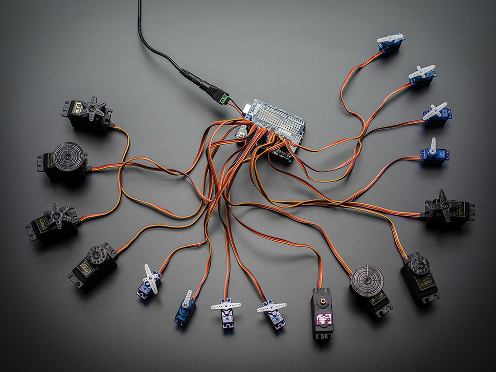
If you’re building a robot or project with lots of servos (hexapods, animatronics, kinetic art, pan/tilt arrays, etc.), the PCA9685 makes it much easier. Instead of trying to plug many servos directly into an Arduino’s limited pins, the PCA9685 provides up to 16 servo outputs using a simple two‑wire connection (I2C) to the Arduino.
This setup is commonly used with Arduino boards that accept shields such as the Uno, Leonardo, Mega, or ADK. We recommend the Arduino Uno for beginners because it’s compact, inexpensive, and works great with ARC when loaded with the correct EZB firmware.
-
You load EZB firmware onto the Arduino.
This turns the Arduino into a controller that ARC can talk to. -
The Arduino talks to the PCA9685 board.
The Arduino sends I2C commands (usually over pins SDA/SCL). The PCA9685 generates stable servo pulses for up to 16 channels. -
ARC controls the servos.
In ARC you add servo controls/scripts and ARC sends commands through the Arduino (EZB firmware) to the PCA9685 outputs.
-
Servo power: Servos often need more power than USB can provide. In most builds you will use a separate 5–6V power supply for servos.
Tip: Many servo issues (jittering, resetting, random movement) are power-related.
- Common ground: If you use a separate servo power supply, make sure the GND (ground) of the servo power supply is connected to the GND of the Arduino/PCA9685 system.
- Servo count: The PCA9685 provides 16 channels. You can often stack or chain boards in some setups, but start with one board until everything works.
- Firmware choice matters: Different firmware builds exist for different Arduino + PCA9685 configurations. If one firmware does not match your hardware layout, ARC may connect but servo channels may not respond as expected.
Choose one of the firmware packages below. If you’re unsure which one to use, start with the newest official-looking option first, then try the others if needed.
-
ESP32Cam
For ESP32 Camera
-
Mickey's Firmware (Mar 4, 2019)
Useful if you have a similar build to Mickey’s original shield-based configuration.
-
EZ-Genuino_Uno_Adafruit_16_Servo_Shield.zip (Dec 11, 2022)
Newer firmware option for Arduino Uno + Adafruit 16-Channel PWM/Servo Shield style setups.
-
Miller's Generic PCA9685 EZB_UNO_PCA9685.zip
Generic PCA9685 firmware option (often helpful for non-shield PCA9685 breakout boards).
After downloading the firmware, follow the step-by-step tutorial to install it on your Arduino: https://synthiam.com/Tutorial/17526
What you will do in the tutorial:
- Install and open the Arduino IDE.
- Open the firmware project you downloaded (ZIP file).
- Select your Arduino board type (ex: Uno) and correct COM port.
- Upload the firmware to the Arduino.
- Connect ARC to the Arduino running EZB firmware.
- Add servo controls in ARC and test a single servo first (one channel) before connecting all servos.
- If a servo moves the wrong direction or doesn’t reach the expected range, use ARC servo configuration options (such as reverse and limits) to fine-tune motion.
- If servos jitter or ARC disconnects, re-check your power supply and ensure all grounds are connected together.

comment removed now
OK Guys I was able to get this to work for me after making changes to the firmware please try the attached file. I have put comments in the code around my changes. DJ please review and test so you can update the package above..
EZ-Genuino_Uno_Adafruit_16_Servo_Shield-SMM.zip
comment removed
What did not work? was there and issue with the zip?
That's ok,
Micky's and DJ,s code work, and my modified file works well also
Comment removed as I don't like post large code scripts.
@ smiller29 - Solid work my friend, I am a amateur extra VE out of middle TN, will shoot you an email. Everything works on both breakouts. A++/ Knew I wasn't crazy!
@DJ - Thanks for posting the code up top. Proves the community based center this program has. Look forward to contributing as well. Have several projects to share soon, time allowing.
@EzAng - Thankful for your input too, seems its a specific issue, the more the community knows the better!
Question for the group how many PCA9685 can be chained together using this firmware and ARC? The below is how you would do it writing code without ARC.
Chaining Drivers Multiple Drivers (up to 62) can be chained to control still more servos. With headers at both ends of the board, the wiring is as simple as connecting a 6-pin parallel cable from one board to the next.
Addressing the Boards Each board in the chain must be assigned a unique address. This is done with the address jumpers on the upper right edge of the board. The I2C base address for each board is 0x40. The binary address that you program with the address jumpers is added to the base I2C address.
To program the address offset, use a drop of solder to bridge the corresponding address jumper for each binary '1' in the address. adafruit_products_2012_10_13_IMG_0692-1024.jpg Board 0: Address = 0x40 Offset = binary 00000 (no jumpers required) Board 1: Address = 0x41 Offset = binary 00001 (bridge A0 as in the photo above) Board 2: Address = 0x42 Offset = binary 00010 (bridge A1) Board 3: Address = 0x43 Offset = binary 00011 (bridge A0 & A1) Board 4: Address = 0x44 Offset = binary 00100 (bridge A2)
etc.
In your sketch, you'll need to declare a separate pobject for each board. Call begin on each object, and control each servo through the object it's attached to. For example: