
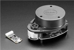
Slamtec Lidar driver for ARC; scans 360° and publishes distance data to NMS for mapping, obstacle avoidance, and navigation.
 Hardware Info
How to add the Rplidar robot skill
- Load the most recent release of ARC (Get ARC).
- Press the Project tab from the top menu bar in ARC.
- Press Add Robot Skill from the button ribbon bar in ARC.
- Choose the Navigation category tab.
- Press the Rplidar icon to add the robot skill to your project.
Don't have a robot yet?
Follow the Getting Started Guide to build a robot and use the Rplidar robot skill.
How to use the Rplidar robot skill
NMS Lidar is the robot skill driver for all Slamtec Lidars (e.g., A series, C series, and S series). It pushes scan data to the ARC NMS (Navigation Messaging System) as a level #3 Group #1 sensor. Read the NMS manual page to learn how this skill can be combined with a mapping robot skill for navigation.
In simple terms, this robot skill will collect distance data from any Slamtec lidar sensor by scanning a 360-degree circle around the robot. It then pushes that data to another robot skill that can display it and use the information for navigation. The NMS manual explains how to set it up, and some videos also demonstrate the process with similar hardware.
Lidar Placement & Offset Configuration
Correctly positioning and configuring your lidar is essential for accurate mapping, obstacle avoidance, and robot localization. This section explains how to determine the correct forward/backward offset and rotation angle, and how these settings impact the scan data in your robot’s coordinate system.
Robot Center: Where to Measure From
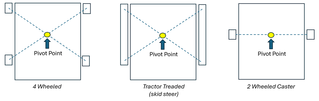
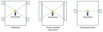
The robot center is not necessarily the physical center of the chassis. Instead, it's the pivot point - the spot on the robot that stays in place while the robot spins in place (rotates).
- On differential drive robots, this is usually the midpoint between the two drive wheels.
- On mecanum or omni-wheel robots, it's typically the center of the wheel pattern (e.g., the middle of the "X").
- On Ackermann-style robots (steering like a car), the pivot point is more complex and based on the turning radius, but often approximated near the rear axle.
Before we continue introducing the offset options, note that it is preferable to place the Lidar sensor at the center of the robot, as described above. However, offsets are introduced below that can be used if needed.
To find your robot’s pivot point, place it on the floor and command it to rotate in place. The spot on the ground that doesn't move is the rotational center. Use this point as your reference when measuring offsets.
FORWARD/BACKWARD OFFSET (in cm)
The Forward/Backward Offset setting lets you specify how far the lidar is mounted in front of or behind the robot’s center point.
- A positive value means the lidar is in front of the robot's center (closer to the front bumper).
- A negative value means the lidar is behind the robot's center (closer to the back).
Measure this in centimeters using a straight line from the robot's pivot point (not just its body) to the center of the lidar unit.
This setting adjusts the scan points so that all distance and angle readings are interpreted as if the lidar were placed exactly at the robot's center. It is essential for accurate navigation and mapping.
ROTATION OFFSET (in degrees)
The Rotation Offset lets you correct for how the lidar is mounted in terms of rotation.
- 0 (or 360) means the lidar’s "forward" scan direction matches the robot’s forward movement direction.
- 90 would mean the lidar’s forward direction is pointing to the robot's right side.
- 180 flips the lidar backward (facing the rear).
- 270 makes it face the robot’s left side.
You can experiment with this by holding the robot still and observing the live lidar display. Adjust the rotation angle until objects in front of the robot appear in the forward direction on the scan display.
Why These Settings Matter
When the lidar is off-center or rotated incorrectly:
- Obstacles appear in the wrong place.
- The robot may "think" it’s hitting walls that aren’t there.
- SLAM maps are inaccurate.
- Path planning and navigation are compromised.
By adjusting these settings:
- All lidar data is transformed into the correct coordinate space (relative to the robot’s pivot).
- Your robot can navigate and understand its environment with precision.
Recommended Best Practices
- Mount the lidar as close to the robot's center as possible to minimize distortion from rotation.
- Secure the lidar so that it doesn’t shift position during movement.
- Always double-check that the forward direction is aligned with 0 in the configuration.
- Use the robot’s live scan visualization to verify that real-world objects appear where they should.
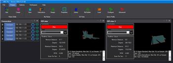
Main Window
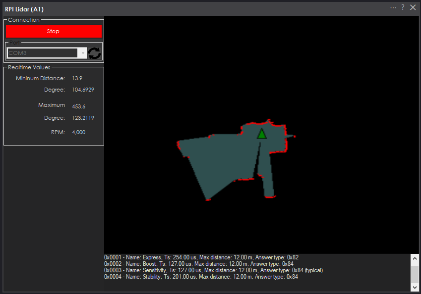
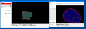
Select the COM port from the drop-down menu when connecting to the Lidar and press START. There are also control commands to start and stop the lidar. If you need to change the COM port or adjust settings, use the configuration menu. By default, this robot skill will use the suggested default scanning mode for the lidar. With this robot skill, you cannot change the scanning mode; it will use the default. Upon connection, you will see the console preset data for the product model, version, firmware, and scan modes.
The COM port must be a serial device on the PC, as the RP Lidar driver from SlamTec does not support feeding the data programmatically from a microcontroller UART unless the microcontroller is detected as a COM device on the PC, such as an Arduino with a firmware programmed to be a COM<->UART adapter. For example, you cannot connect a Lidar to an EZB for this robot skill, as it requires a dedicated COM<->UART adapter.
Configuration
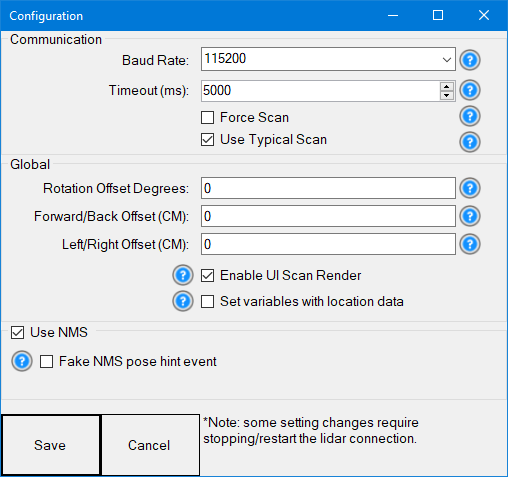
Communication Settings
1) BaudRate dropdown The baud rate for the communication. The dropdown presents a few options for you to choose or enter the value manually. The baud rates for Slamtec LIDARs vary by model and communication mode. Here’s a summary of commonly supported baud rates for Slamtec RPLIDAR devices:
RPLIDAR A1 (Standard Edition):
- Default baud rate: 115200 bps
RPLIDAR A2 (Performance Edition):
- Default baud rate: 115200 bps
- Other supported baud rates: Configurable in firmware, but 115200 is standard.
RPLIDAR A3 (Enhanced Performance):
- Default baud rate: 256000 bps
RPLIDAR S1 (Advanced Model):
- Default baud rate: 256000 bps
RPLIDAR S2 (High Precision):
- Default baud rate: 256000 bps
RPLIDAR T1 (TOF Technology):
- Default baud rate: 256000 bps
RPLIDAR C1:
- Default baud rate: 460800 bps
2) Timeout (ms) The operation timeout value (in milliseconds) for the serial port communication
3) Force Scan Force the core system to output scan data regardless of whether the scanning motor is rotating. This should be used only for debugging, as a jammed motor or unit can damage the lidar.
4) Use Typical Scan Use lidar's typical scan mode or compatibility mode (2k sps). The default is checked.
Global Settings
1) Offset Degrees Correct the angle at which the lidar is mounted. If you find the map reversed, type 180 in this field to rotate the lidar scan data 180 degrees.
2) Offset Forward/Back The lidar's offset is in centimeters relative to the robot's absolute center: positive values indicate a forward offset, while negative values indicate a rearward offset. Use decimal values for MM to ensure very precise results. If this value is not precisely calculated from the robot's pivot center, your rendered SLAM map will be incorrect.
3) Offset Left/Right The lidar's offset is in centimeters from the robot's absolute center: positive values indicate a right placement, while negative values indicate a left placement. Use decimal values for MM to ensure very precise results. If this value is not precisely calculated from the robot's pivot center, your rendered SLAM map will be incorrect.
4) Enable UI Scan Render This will enable the scan map to be rendered to the robot skill's display. On a headless setup, this can be disabled to save performance. Most systems gain no benefit from enabling this, other than during debugging. Disabling this will save CPU performance.
5) Set variables with location data If you're not using the NMS, check this option to create global variables for the scan data containing the nearest/furthest degrees and distances from the most recent scan. Otherwise, keep this unchecked because it will use a significant amount of CPU if you're not using these variables. This sets the 4 variables so you can receive the nearest and furthest values.
NMS Settings
1) Use NMS If this is checked, the lidar data will be published to the NMS (Navigation Messaging Service), which allows other navigation robot skills, such as The Better Navigator, to use the lidar distance data.
2) Fake NMS Pose hint event Navigating robot skills, such as The Better Navigator, can use the Hector SLAM pose hint, which will not require a pose sensor. You can enable this option if you have The Better Navigator configured to use Hector as the pose hint. This will send a "fake" pose hint of 0,0 to the NMS, so the pose event runs after every lidar scan. If you use a wheel encoder or other pose sensor, leave this checkbox empty.
NMS (Navigation Messaging System) Stack
This skill operates in Level #3 Group #1 and publishes obstacle detection to the NMS. While some SLAM systems will attempt to determine the robot's Cartesian position without telemetry, it is best to combine this skill with a Group #2 sensor. Read the entire manual of the NMS.

---
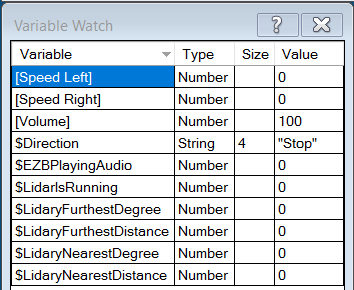
Variables You can view the variables this skill creates in the configuration menu of this control. The variables hold the most recent values of the lidar's minimum/maximum distance, degrees, and running status.
Control Commands for the Rplidar robot skill
There are Control Commands available for this robot skill which allows the skill to be controlled programmatically from scripts or other robot skills. These commands enable you to automate actions, respond to sensor inputs, and integrate the robot skill with other systems or custom interfaces. If you're new to the concept of Control Commands, we have a comprehensive manual available here that explains how to use them, provides examples to get you started and make the most of this powerful feature.
Control Command ManualcontrolCommand("RPLidar", "Start")
- Start the RP Lidar robot skill by connecting to the lidar and begin scanning.
controlCommand("RPLidar", "Stop")
- Stop the RP Lidar robot skill and stop scanning.
Related Questions
Rplidar A1 And Better Navigator
Rplidar C1 Not Working
Multiple Rplidar Skills Issue

Upgrade to ARC Pro
Get access to the latest features and updates before they're released. You'll have everything that's needed to unleash your robot's potential!
It's great to have this Skill available, but until now I just got this screen
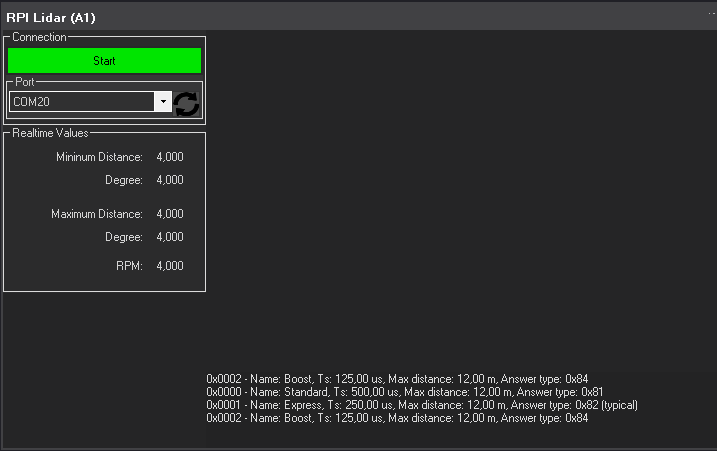
I push Start and only takes a couple to seconds to return again to Start with that message. I appreciate any suggestion to continue. Also any video showing how this works together with the new Navigator would be great.Pablo
Try the latest version - see if that works for your model. There's a few differences amongst RPI models
The Better navigator is probably a smarter choice for this device. You can read about it on it's manual page and the NMS page. There's about 5-6 videos related to the NMS that you can watch on it. Also it's the same as using the Hitachi Lidar, so the videos and hack videos will be the same for this.
Thanks DJ for the very fast reply!!, unfortunately I am having the same result. I checked the lidar with the serial terminal and is answering the Hex commands like reset, start scan etc. , also the Frame Grabber app and is displaying ok the scan. I Appreciate any other comment or suggestions. Pablo
I don't have one to test with - so i ordered one. It'll be here this week. I can take a closer look in a week to find out what is going on
That sounds good. Thank you!
Keep your eye on this robot skill instead of the navigator: https://synthiam.com/Support/Skills/Navigation/The-Better-Navigator?id=20956
This one is The Better Navigator and has more innovative path planning - and fuses multiple telemetry sensors to get a better pose estimation. It's still in development, and I'm working on it tonight while I type this. There are a few tweaks I'm finishing. I think it'll be awesome.
Excellent. By the way I have the intel realsense 435 and T265 to feed the navigator also. I will be ready to test it!.
Nice - you can try The Better Navigator now if you wish. It "sort of" works but doesn't have auto path planning with the current version.
Actually, you can add all three sensors (realsense & lidar) for The Better Navigator to get even more data fusing lol.