Hitachi-LG LDS 360-degree LiDAR driver streaming scans into ARC NMS for obstacle detection, SLAM use, Arduino hookup, config options and variables.
 Hardware Info
 Source Code
How to add the Hitachi-LG LDS Lidar robot skill
- Load the most recent release of ARC (Get ARC).
- Press the Project tab from the top menu bar in ARC.
- Press Add Robot Skill from the button ribbon bar in ARC.
- Choose the Navigation category tab.
- Press the Hitachi-LG LDS Lidar icon to add the robot skill to your project.
Don't have a robot yet?
Follow the Getting Started Guide to build a robot and use the Hitachi-LG LDS Lidar robot skill.
How to use the Hitachi-LG LDS Lidar robot skill
NMS Driver for the Hitachi-LG LDS 360-degree lidar. This robot skill connects to the Lidar and pushes the data into ARC's NMS (navigation messaging system) to be used with level 1 navigation viewers. To understand how this skill can be used, reference the NMS manual page.
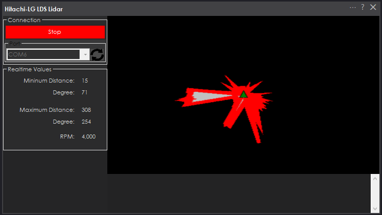
Screenshot
Configuration

1) BaudRate value The baud rate for communication to the USB serial adapter or Arduino. By default, the baud rate for the lidar should be 230400. However, some USB serial converters use different baud rates between the PC's USB port. The baud rate between the lidar and USB adapter must be 230400.
2) Offset Degrees value Correct the angle that the lidar is mounted
3) Advanced communication parsing checkbox Include debug information in the log window. This is only recommended if asked by Synthiam to help debug a communication issue. Otherwise, this will use a lot of resources.
4) Set variables with location data checkbox If you're not using the NMS, check this option. The global variables will be created for the scan data if this checkbox is checked.
5) Fake NMS Pose hint event checkbox The Better Navigator can use the Hector SLAM pose hint, which will not require a pose sensor. You can enable this option if you have The Better Navigator configured to use Hector as the pose hint. This will send a "fake" pose hint of 0,0 to the NMS so that the pose event will run after every lidar scan.
6) RTS Enabled checkbox RTS (Ready To Send) is an optional signal line for UART communication. Some USB adapters, specifically some Arduinos, may require this to be enabled. If your USB Serial adapter is not responding, you may need to enable or disable this option.
7) DTR Enabled checkbox DTR (Data Terminal Ready) is an optional signal line for UART communication. Some USB adapters, specifically some Arduinos, may require this to be enabled. If your USB Serial adapter is not responding, you may need to enable or disable this option.
NMS (Navigation Messaging System)
This skill operates in Level #3 Group #1 and publishes obstacle detection to the NMS. While some SLAM systems will attempt to determine the robot's cartesian position without telemetry, it is best to combine this skill with a Group #2 sensor.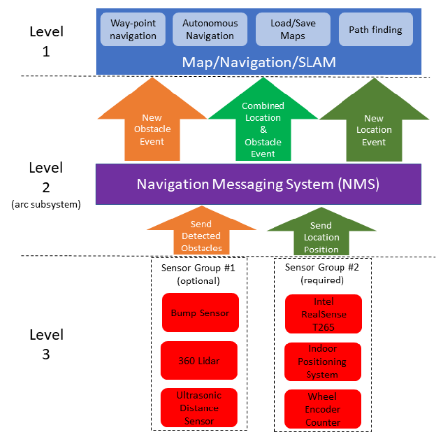
A recommended navigation robot skill is The Better Navigator, which uses the NMS data.
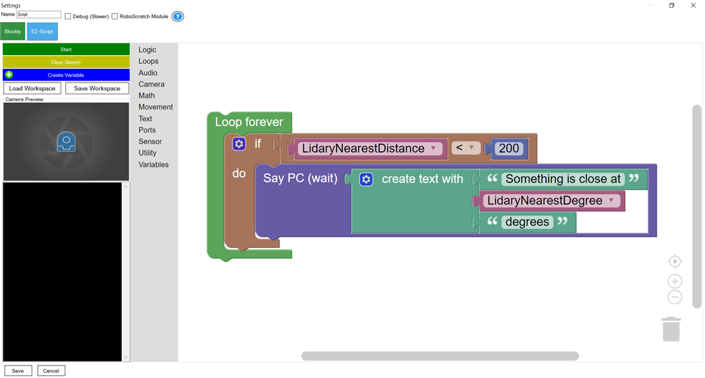
Program the LIDAR in Blockly Like all Synthiam controls, the Blockly programming language can be used. In the example below, the robot will speak when an object has come close to it. It will also speak the degrees of where the object was. To see this program in action, click HERE.
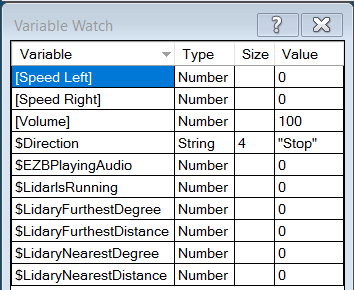
Variables You can view the variables this skill creates in the configuration menu of this control. The variables hold the most recent values of the lidar's minimum/maximum distance, degrees, and running status. Here is a list showing the variables using the Variable Watcher robot skill.
Arduino Sketch
There are two ways to connect to this lidar. You can use a standard USB<->UART converter, such as those on Amazon or eBay. Or you can use a 32u4-based Arduino board (i.e., Micro) to make your own USB<->UART converter. The 32u4-based boards are necessary Arduino versions because they support emulating USB HID devices, such as serial devices.Here is a simple sketch that can be used on a 32u4-based board...
void setup() {

   Serial1.begin(230400); // Init Hardware Serial port on pins 0 and 1
   Serial.begin(230400);  // Init Serial Port
}

void loop() {

  if (Serial.available())
    Serial1.write(Serial.read());

  if (Serial1.available())
    Serial.write(Serial1.read());
}
Wiring
GREY - Ground RED - +5 GREEN - RX (connects to TX on Arduino or USB Converter) BROWN - TX (connects to RX on Arduino or USB converter)Robotis USB <-> UART Converter
The Robotis version of this sensor may include their USB UART converter, which uses a CP210x chipset. The driver for Windows can be found by clicking here: CP210x_Windows_Drivers.zipVideos
Real-time SLAM mappingRoom Mapping
Near Object Detection

v16 - updated to allow not setting variables to save on performance
v19 updated
Ahh ordering one today! Having this in the toolbox would be significant!
Does it matter which way the Lidar is mounted? Upright or upside down? I assume it doesn't matter to the Lidar ... lol ... but would the software have a problem with it? Asking before mounting.
Thanks
Look at the top of the page and you’ll see the manual that has an option for offset.
Rotation is fine but upside down is never allowed for lidars. It’s the mechanics of how it spins and the bearings and such. They can’t mount upside down
Dear friends@DJ Sure honest greetings and respect same problem to integrate the lidar for obstacle avoidance I'm using CH340G TTL to USB
System.Exception: Lidar service parse error: System.Exception: No data received by lidar. Giving up at Hitachi_LG_LDS_Lidar.LidarServiceUART.imageThreadWorker(EZTaskScheduler sender, Int32 taskId, Object o) in C:\My Documents\SVN\Developer - Controls\In Production\Hitachi-LG LDS Lidar\MY_PROJECT_NAME\LidarServiceUART.cs:line 136 at Hitachi_LG_LDS_Lidar.LidarServiceUART.imageThreadWorker(EZTaskScheduler sender, Int32 taskId, Object o) in C:\My Documents\SVN\Developer - Controls\In Production\Hitachi-LG LDS Lidar\MY_PROJECT_NAME\LidarServiceUART.cs:line 182 at EZ_B.EZTaskScheduler.y1RE8o6AKZlNc2N1TErk(Object , Object , Int32 taskId, Object ) at EZ_B.EZTaskScheduler.Pdg6igBoDpW()
Hello to you as well!
I would assume the tx and rx may be reversed. The lidar should start spinning if it receives the correct "start" command. At that point, the lidar begins dumping its sensor data.
Recheck the wiring to ensure the lidar is connected correctly to the usb serial adapter.
dear @DJ Sures thanks alot for you fast replay
tx and rx not reversed start command from interface button start spinning and stop after while
please advice thanks a lot in advance