NMS Driver for the Hitachi-LG LDS 360 degree lidar.
How to add the Hitachi-LG LDS Lidar robot skill
- Load the most recent release of ARC (Get ARC).
- Press the Project tab from the top menu bar in ARC.
- Press Add Robot Skill from the button ribbon bar in ARC.
- Choose the Navigation category tab.
- Press the Hitachi-LG LDS Lidar icon to add the robot skill to your project.
Don't have a robot yet?
Follow the Getting Started Guide to build a robot and use the Hitachi-LG LDS Lidar robot skill.
How to use the Hitachi-LG LDS Lidar robot skill
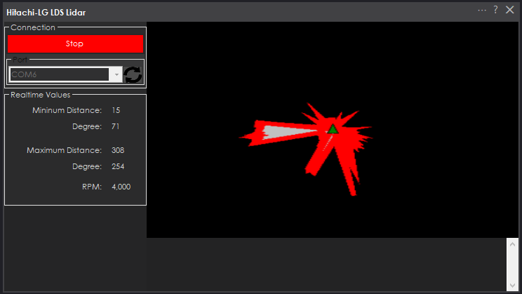
NMS Driver for the Hitachi-LG LDS 360 degree lidar. This robot skill connects to the Lidar and pushes the data into ARC's NMS (navigation messaging system) to be used with level 1 navigation viewers. Read the NMS manual page to understand how this skill can be used.
Screenshot
Configuration
1) BaudRate The baud rate for the communication to the usb serial adapter or arduino. By default the baudrate should be 230400 for the lidar. However, some usb serial converters will use different baud rates between the pc usb. The baudrate between the lidar and usb adapter must be 230400.
2) Offset Degrees Correct the angle that the lidar is mounted
3) Advanced communication parsing Include debug information in the log window. This is only recommended if asked by Synthiam to help debug a communication issue. Otherwise, this will use a lot of resources.
4) Set variables with location data If you're not using the NMS, check this; global variables will be created for the scan data.
5) Fake NMS Pose hint event The Better Navigator can use the Hector SLAM pose hint, which will not require a pose sensor. You can enable this option if you have The Better Navigator configured to use Hector as the pose hint. This will send a "fake" pose hint of 0,0 to the NMS so that the pose event will run after every lidar scan.
6) RTS Enabled RTS (Ready To Send) is an optional signal line for UART communication. Some USB adapters may require this to be enabled, specifically some Arduinos. If your USB Serial adapter is not responding, you may need to enable or disable this option.
7) DTR Enabled DTR (Data Terminal Ready) is an optional signal line for UART communication. Some USB adapters may require this to be enabled, specifically some Arduinos. If your USB Serial adapter is not responding, you may need to enable or disable this option.
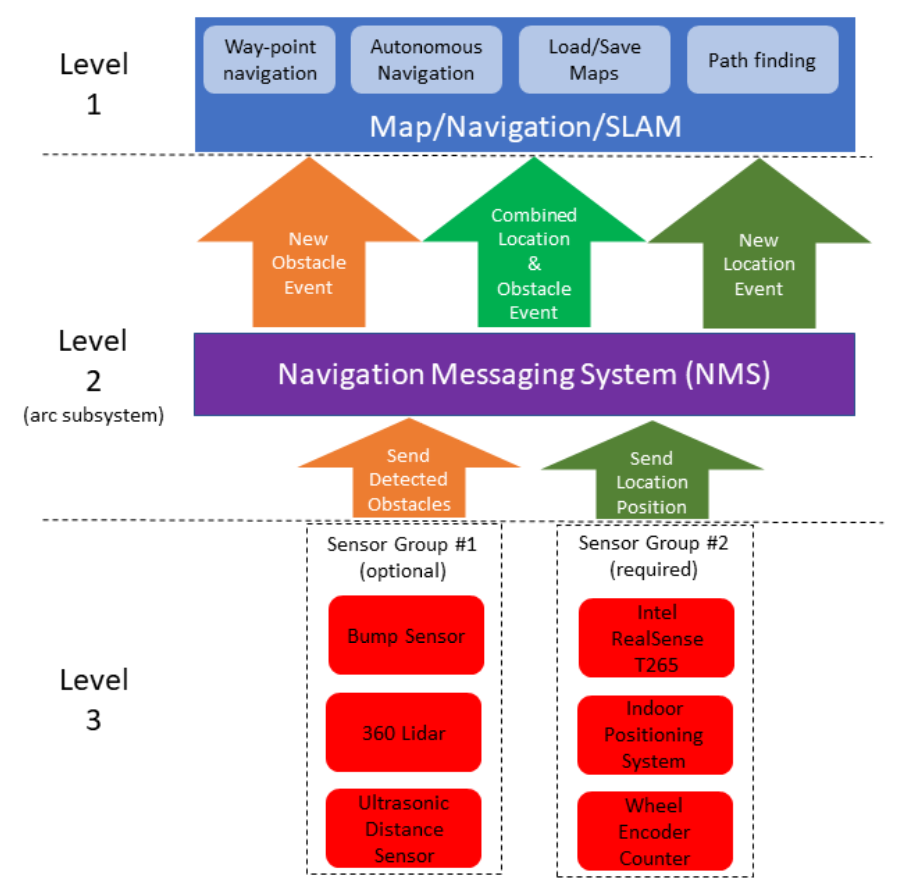
NMS (Navigation Messaging System)
This skill operates in Level #3 Group #1. It publishes obstacle detection to the NMS. While some SLAM systems will attempt to determine the cartesian position of the robot without telemetry, it is best to combine this skill with a Group #2 sensor.How to Use EZ-LIDAR SLAM
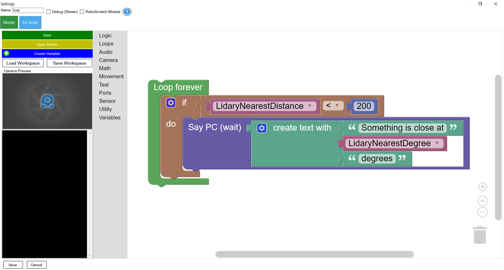
Program the LIDAR in Blockly Like all Synthiam controls, the Blockly programming language can be used. In this example below, the robot will speak when an object has come close to it. It will also speak the degrees of where the object was. To see this program in action, click HERE.
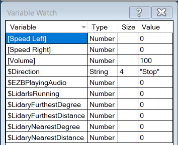
Variables In the configuration menu of this control, you can view the variables that this skill creates. The variables hold the most recent values of minimum/maximum distance, degrees, and running status of the lidar.
Arduino Sketch
There are two ways to connect to this lidar. You can either use a standard USB<->UART convertor, such as those found on amazon or eBay. Or you can use a 32u4 based Arduino board (i.e. Micro) to make your own USB<->UART converter. The 32u4 based boards are necessary Arduino versions to use because they support emulating USB HID devices, such as a Serial device.Here is a simple sketch that can be used on a 32u4 based board...
void setup() {
Serial1.begin(230400); // Init Hardware Serial port on pins 0 and 1
Serial.begin(230400); // Init Serial Port
}
void loop() {
if (Serial.available())
Serial1.write(Serial.read());
if (Serial1.available())
Serial.write(Serial1.read());
}
Wiring
GREY - Ground RED - +5 GREEN - RX (connects to TX on Arduino or USB Converter) BROWN - TX (connects to RX on Arduino or USB converter)Robotis USB <-> UART Converter
The Robotis version of this sensor may include their USB UART converter, which uses a CP210x chipset. The driver for windows can be found by clicking here: CP210x_Windows_Drivers.zipVideos
Real-time SLAM mappingRoom Mapping
Near Object Detection
Is this the same hardware? https://www.robotis.us/360-laser-distance-sensor-lds-01-lidar/
The hardware link above goes to a Hitachi-LG page specs but no link to purchase the device, and searching Google I can't find it for sale anywhere with that specific name.
Alan
Yah - it's the same but i don't think you can buy this easily. It's difficult to find but the only lidar i currently have to test with at the moment. This was the lidar that we had partnered with hitachi-lg to distribute back at the ez-robot days. Robotis uses it in their waffle and burger. There's a number of more cost effective lidar's at robotshop i think
Since the NMS is so versatile, we can start adding more 360 degree lidars. If you guys decide on one that you think is a good fit, let me know and i'll add an NMS driver for it.
Neato has an affordable lidar ($80) ...you can get some used ones on ebay for about $40.
Guys,
I have the lidar, I'm using in one of my bots with ROS.DJ wrote multiple times they were working in releasing a EZ-Robot lidar so I didn't wanted to create any competition between Robotis Lidar and the EZ-Robot Lidar.
And I have that one also in another bot. David (Cochran Robotics) wrote a plugin, so I didn't wanted to create a duplicate plugin. It seems David never finished the plugin, and he left the forum so maybe make sense to wrap up a plugin.I'll write a plugin for both Lidars.
Hey wow PTP, DJ, we have more on Lidar this year than anything last year, even if 2020 was terrible ,the start of 2021 looking brighter already!
Wow thanks @PTP the Neato starts at around $36 on Ebay + about $10 shipping so this meets the wife doesn't need to know about it price category. https://www.ebay.com/sch/i.html?_from=R40&_trksid=p2380057.m570.l1313&_nkw=neato+xv11+lidar&_sacat=0
Besides the Neato you will need an arduino micro (Leonard) has a serial port and a small h-bridge (<$10) to control the lidar RPM. I'll do a video and I'll post the details.
PTP - Actually I'm modifying the lidar plugin to connect directly with the lidar via a USB <-> UART
I haven't done it yet - but it's what i'm working on next. Less hardware needed
The Robotis has already an usb connection.
I'm talking on this thread topic. thread topic fail.
ha ok ! Sorry today I'm little slow too many conference calls ...
I got it! you are adding usb support to this plugin (Hitachi) and as consequence will be compatible:
Yup! And connecting it to a cheap esp32 for wifi ability as well
Well, I took the leap of faith that you will continue down this path of room mapping and autonomous navigation and signed up for PRO for a year, even though I need new batteries for all of my bots before I can do anything. Going to wait to buy the Lidar and Intel Realsense until you are a little further along, but if it all comes together I think that will jumpstart me to finally get off my behind and start building my dream bot from scratch.
Alan
Welcome and thanks!
@DJ: I tried the plugin with the Robotis Lidar:
I don't see output in the Plugin, Navigator, Ez-Lidar SLAM I presume the reason is below:
Oh, the reason is the COM port connects to our LDS controller, which sends different data. I haven't modified this skill to work with a generic usb/uart adapter yet. Robotis is sending me a wafflebot which i'll be using for this skill.
In the meantime, if you feel like making your own or modifying this skill - i can give you the code here: Hitachi-LG LDS Lidar.zip
What the skill is to do... it'll display each received frame of the LDS, no problem. Then it'll forward it's data to the navigator using the ARC.MessagingService.Navigation2DV2.Messenger.UpdateCanPoints
Because the lidar doesn't send any localization/position information, the navigator won't render the lidar data. It'll need something to positioning data: https://synthiam.com/Support/ARC-Overview/robot-navigation-messaging-system
howver, you could "fake" positioning with a simple javascript command in the Navigation namespace during your tests. Because you may not have another way of setting a position of the sensor (i.e. intel realsense is preferred). The iRobot Roomba and Wheel encoder skill haven't fully been tested with the NMS yet, so i'd hold off on testing with them.
Oh I should add that The Navigator uses Cartesian coordinates. Which means I have to modify the roomba skill and wheel encoder firmware to calculate that
DJ: I found the method:
So if the UpdateScan is successfull, is expectable to see something on the Navigator and the EZ-Slam ?
Not with The Navigator. The Navigator also requires an UpdateLocation() as well. Each navigation type skill can decide what to use. The Navigator requires at least the UpdateLocation()
You can simulate UpdateLocation in JavaScript by using the Navigation.UpdateLocation() method for faking it.
Just make a script with ....
That'll update the latest scandata information at cartesian coordinate 0,0 with a heading degree of 0. Every time you submit an updateLocation into NMS, The Navigator will take what ever scandata has been accumulated and process it.
NMS Navigation controls don't HAVE to operate that way. But The Navigator does. It ensures the updating location is synchronized with the latest scan data
ptp, this skill has been updated and works now with the generic usb<>uart converter.
Here's The Navigator & EZ-SLAM both getting data from the Hitach-LG LDS-01 360 degree lidar
Outstanding news! " and dats the fact Jack!"---Stripes 1980's:p
@DJ: Quick feedback, I had a break and I've updated all the components and run a new test, and the plugin is still not working (protocol parser).
I plan to schedule a robot lobotomy during the weekend, so I'll get more time to play/test all the hardware.
*** Edited *** @DJ: Every time I edit a post in this thread goes back to this page: https://synthiam.com/Support/Skills/Navigation/EZ-SLAM?id=15944
ptp, do you know if the USB<->UART converter that you're using has a specific baud rate?
Also - is it just a usb<->uart converter or is it controlling commands and parsing data as well?
My LDS is connected through a Arduino Leonardo/Micro (emulates USB device) using this high-tech code
If your USB<>UART converter is indeed just that, it will work and at that baudrate. Otherwise, i'll need to know more about it.
Added github repo
Hi DJ, could you post the wiring shematic and .ino file you used to get it running? There are some of these lidars on ebay at a nice price.
Wiring schematic is in the GitHub repo
arduino code is the lost above yours
I found the Hitachi on US Ebay for ~$40, although taking a slow boat from China so won't be here until March. I think it is the same vendor that @proteusy found.
Is this the right github link? https://github.com/synthiam/E-41_LIDAR
I don't see the wiring diagram.
Do you think this USB to TTL will work? I already have a set. https://amazon.com/gp/product/B07D9R5JFK/
Trying to have everything ready when it gets here. I got my Realsense camera this morning.
Alan
Click here...
I also added the sketch and wiring to this manual page
Thanks. I was on the wrong Github link.
Alan
Hi Alan, i was thinking of using a FTDI Uart to Usb dongle. @DJ, how did you wire the Lidar motor? Did you use PWM or wired the 5V directly?
The wiring is in the manual above. Just connect the +5 and ignore the pwm wire
@proteusy
I do have a spare one of those as well. I was saving it to convert an EZ-B to USB, but the Spark fun ones are cheap, so that may be an option as well. Although the one I have is a 3.3v, so I may need a different one (supposedly it can be changed to 5v by soldering across a couple of pads on the board, but I don't want to screw it up with my bunny hug soldering skills).
If you find any usb<->uart's online (or amazon), make sure they say windows 10. Because a lot of those ftdi chips don't have win10 drivers... or, you have to search the internet to find them LOL
Sparkfun has a link to the ftdi drivers. The issue now is that it appears all of the eBay sellers of the Lidar are actually the same guy and none are in stock, and none expected until after the Chinese New Year month long holiday.
Alan
Here are a few Lidars
LD LIDAR
@proteusy
That is the guy who just told me he was out of stock and it turned out to be the same one I had already tried to order from. Can't find any who actually have them.
@thetechguru Yep, right...
I found a commercial retailer who seems to have them in stock, but it is the 1.0 version for $179 US, not the 1.5. https://dabit.industries/products/360-laser-distance-sensor-lds-01-lidar
I am willing to go around $100 for something guaranteed to work for object avoidence in NMS, but $179 for what might not be the right one seems a little rich. Hitachi now has a 2.0, but I can't find them for sale anywhere. Probably just selling to vacuum manufacturers.
I guess I am stuck with ultrasonic object avoidence for now. It is OK, but misses soft surfaces like curtains. May need to rig up a bump sensor, or get some more Sharp IR to augment. (I use a Sharp for cliff detection because there is a step down into my family room, but I don't think I'll need it using way point nav with the Real sense, So I might repurpose it).
If you guys can find another lidar (say from robotshop or somewhere accessible in stock) then we can can add support to that.
Alan, you could use a simple ultrasonic distance sensor for obstacle avoidance with the NMS. The Navigator will pause navigation and launch a script when obstacle has been detected. That's configurable in the config menu.
Robot shop has 2 sub $100 devices in stock.
https://www.robotshop.com/en/rplidar-a1m8-360-degree-laser-scanner-development-kit.html
Although a review I read in the reviews that the SDK was written by a drunken lobster, and https://www.robotshop.com/en/ydlidar-x2-360-laser-scanner.html which I believe is a brand you complained about the SDK in another thread, although I could be mis remembering.
For my initial experiments, I am fine using Ultrasonic because it should work well enough in my basement, but if I don't get something much more precise, I won't ever be able to run it on the main floor, because if I dent the maple dining set, my wife will first destroy the robots, and then kick me out of the house
Ha that’s funny. I usually say drunken sailer but a drunken lobster is pretty good!
Added options in the config menu for Baud Rate and Offset Degrees.
@PTP, this will work with the robotis USB <-> UART converter. You'll need to install the CP210x Windows Driver though. Because they're using a chipset that doesn't have a default windows driver. Get it from the manual link above
This is a follow up from the thread: https://synthiam.com/Community/Questions/Distance-detection-for-NMS-20392 post: #31
I got a new Lidar Hitachi lidar from ebay: https://www.ebay.com/itm/360-degree-LiDAR-sensor-ranging-distance-scanning-module-ROS/313448191749
The lidar has 2 connectors:
Pinout:
You need to connect:
LDS 6 Pin: BLACK <---> Arduino or USB/UART - GND RED <---> Arduino or USB/UART - 5V GREEN <---> Arduino or USB/UART - TX BROWN <---> Arduino or USB/UART - RX ORANGE <--> MOTOR Black wire BLUE - free
LDS 2 Pin: BLACK <---> LDS 6 Pin ORANGE RED <---> Arduino or USB/UART - 5V
Connecting the Lidar to an USB/UART CP2104
Note: As you can see above there is Y connection for the 5V connection.
CP2104 USB/UART: https://www.adafruit.com/product/3309
And It works with DJ plugin.
Love to see a video with this working in the navigation plug in!!!
Edit: Ordered!
Nice tut ptp. U.S only... damm
Proteus, he ships internationally from his own website. Price is a little lower than the eBay cost too. https://curiolighthouse.wixsite.com/lighthouse/lidar-module
He has some other devices as well, primarily designed for use with Android, but might be interesting to integrate with ARC because they have nice clean housings.
Collin is a great seller..contacted me right away and said it was going right into the post the same day and said to let him know if I had any questions and sent me the above link. Highly recommend.
Thanks guys. I will wait for DJs D435i to arrive and see what he can do with it.
I would like to do LIDAR on my roomba to get a 2D 360 view and I am sure it would help with location tracking and mapping. The problem is it has to sit higher than my robot arm as it blocks the LIDAR but that is not good for object detection on the floor where the roomba main body is. I wonder if I could do 2 LIDAR one in front of Robot arm base and one behind and piece the two together.
The D435 gives a good 3D map but in a narrow band (I was surprised at how well calibrated it was even with factory settings). What we really need is a combination of the two. I am thinking a ring of say 5 or 6 D435 would be perfect as long as the point clouds don’t interfere with each other and mess up the speckled laser triangulation. You could at least do 4 one on each side but it would be fun to see a full spherical 3D map with some pointing upwards as well.
You can have as many lidar's as you like and pump it into the NMS. But, one is enough even with a partially blocked view. Your robot is driving around so it will pick up everything.
Got mine today.
Cool would love to see results
Got mine wired up and working. Still need to mount it to the robot, but it is getting g late and I don't want to mess up anything. Also think I need a faster ftdi adapter than the USB to TTL adapter I am using because I am getting a lot of CRC errors and bad data (negative degrees) and when it detects a close object the degrees can vary by up to 55 or more degrees in either direction from the actual object. The skill also just stops randomly. I'll order a better adapter and see if it makes a difference (I have a Sparkfun ftdi but it is 3.5v, not 5. I think it can be modified by soldering across a pair of pads, but the manual for the device isn't clear. They are cheap enough, I'll just order a 5v one).
Also, make sure the sensor is getting adequate power.
Fist thing I checked.. Getting 5.14v although I didn't look at how many milliamps it is getting. I'll try with a different computer with a powered USB hub in the morning. I'll also try with my Realsense unplugged. Could be that this little tablet can't put out enough juice.
The realsense uses a lot of bandwidth - which surprised me. At first i thought all the processing was done in the sensor. But no....
So make sure the usb ports aren't shared via an onboard hub. Try different ports between the lidar and realsense.
Well, the good news (not really when I think about it) is that my cable is fine. The Lidar works perfectly on another computer. Works better in the USB 3 port instead of the USB 2 port of the tablet, but I suspect the RealSense won't be happy with USB 2.
It might be better if I separate the power and put a voltage regulator so I can run the motor power from the EZ-B instead of the USB port, but the real difference I see is that in the other computer I can set the com port to much higher speed in device manager for the cable, so pretty sure that even thought it says it is USB 3, the tablet may not actually be performing at that level.
If I am going to continue to use Roli as my test bed, I am going to need to figure out how to provide 12 volts to the computer because unlike the tablet, it doesn't have it's own power supply and runs at 12v. The computer itself will just fit on top of Roli, but not sure what I can do for power. I may need to build a trailer for a battery, at which point, maybe I should just be scratch building anyway. I just like how using EZ-Bits I can quickly change configurations. Also, without a screen, it will need to run headless, but that was the plan for the big computer anyway. If I had on board screen at all, it was probably going to be another computer running Anydesk or another remote control app.
Oh well, getting there one step at a time. May be a few weeks before I figure out how to make this all work and get any additional components I need (heck, I don't even have a 12 v charger because my original plan was to use 24 volts and Wheelchair motors, but I have been thinking smaller and slower lately, and my 24v SLA is actually 2 12v batteries wired together, so I can easily split them... Of course, they are way too heavy for Roli to tow, so again, I may need to scratch build platform just for the navigation testing. I have a couple of 12v motors, and plenty of plywood and MDF. Need wheels... final build I want treads, but that can wait. so main items now I think are wheels and a charger).
Alan
I power the rock pix for about 10 hours with this: https://www.amazon.ca/gp/product/B07YPSZKSY/ref=ppx_yo_dt_b_asin_image_o05_s00?ie=UTF8&psc=1
here’s a pic of the setup. The lidar isn’t being used right now because I have an intel realsense array. But that battery pack is amazing.
I have poking around Amazon for similar with 12v output. That will probably be the easiest, and they don't look too expensive.
I just recently got one with 19.4 V volts and 29.4 as well as a USB A and USB C PD to power my guitar amp and as well as extra juice for my laptop. If I had known I would have found one that also does 12v.
Alan
If you require 12v, i use this for my fish finder: https://www.amazon.ca/Talentcell-Rechargeable-6000mAh-Battery-Portable/dp/B00MF70BPU/ref=sr_1_11?dchild=1&keywords=12v+battery+pack&qid=1617069244&sr=8-11
I looked at that one. Good price, but I decided on this one because it will serve other purposes when this test platform project is done and I move everything into a permanent build:
https://smile.amazon.com/dp/B074PQBRJV/ref=cm_sw_r_cp_apa_fabc_PCV52EQQG104F1428A8V
With the faster computer, this is now mostly working. It still gets an error every once in a while, and then stops running after several errors. For now I am just going to script around it (when the variable that shows the lidar is running changes from 1 to 0 I'll issue a ControlCommand() to start it again).
Next time I am working with it I'll capture the error from the log for you.
Alan
Do you just press start and it recovers? What is the error
Yes, it recovers when I press start. I'll have to capture the error from the log next time it happens. In the skill window I see two errors, CRC error, and something about invalid direction, with a negative value for the degrees, usually way over -360 (like -900). Not sure which of those is triggering the stop, and it seems to take 4 or 5 before it does. When I was using the other computer that had a top USB com port speed of something like 124K vs this one where I can leave it on the default (208K?) it happened every minute or so. Now it can run for up to 10 minutes at a time before it happens.
You’re changing the baud rate? The sensor has a standard baudrate and changing it from the default value will create a lot of problems. Specially if you make it lower.
Not on the new computer. I had to on the other computer because the com port wouldn't communicate at all at the default speed (it claimed it was a USB 3 port, but I have doubts. I explained above that it was a cheap Chinese tablet and the eBay seller had issues getting English language Windows 10 drivers, so could be a USB 3 port with a bad driver too) . This one I am using does support the higher speed, so I left it at the default.
Alan
The default baudrate of the usb<->uart adapter wouldn't need to be USB 3, or even USB 2. It would even be fine with usb1 because the baudrate is actually less than 37k/sec. The question would not be the USB port, it would be the USB<->uart adapter supporting a baudrate over 115200, which some do not.
The usb3 is far too overkill at 5Gbps. And even USB 2 is 480Mbps. And USB1 is 12Mbps
The sensor needs 37k/sec which is 0.036133Mbps
Here is the error. It took much longer this time, and I only saw CRC errors, not bad direction errors.
one packet is 2,520 bytes. The error states that there are 20 packets behind in processing. It seems the computer isn't able to process the data quick enough - which is pretty strange because it's not very complicated to process. I'll take a look at the parser and see if there's something i can do from my end. I'm not sure what I'd be able to do to unless something stands out to optimize in my code
I'll run task manager next time and see if there is anything using up resources on the computer that I don't need running. I think it took longer to see the error because of the optimization you did on the Realsense D265 since the last time I ran it.
The change to the Navigator to ignore distances outside of the selected degrees worked perfectly btw.... Drove right along the wall that used to stop it and through a doorway just fine.
Alan
Have you optimized the pc for dedicated robot use? https://synthiam.com/Support/Tips%20to%20Make%20a%20Robot/free-space-with-windows-10
Not yet. It has plenty of disk space, so optimizing space isn't an issue, but I do need to get rid of services I don't need to have running.
Alan
There’s performance tips in there as well. Specifically the hibernate is a big one. Also disabling defender virus scanner thing. And adding power management to prioritize power. Anyway it’s all in there so I’d really advice doing it. Otherwise I wouldn’t have put the effort into making it
Confirmed tonight, issues are definitely CPU related. Was much worse when I connected a higher resolution Logitech web cam so I would have a wider angle view, and CPU was sitting around 93% with bumps up to 100% where the Lidar would shut down. I'll do some optimization before my next set of tests since I would rather spend CPU on script processing than services I don't need running.
Navigator is really cool though. Been running the robot all around my basement just by picking points and telling it to go there. After a few trips, I get a pretty good map of the walls and obstacles so I can set path points without being able to actually see the robot.
Alan
Try limiting the camera display frame rate. I find a lot of video cards can’t handle displaying high frame screen draws
itll still process full speed internally. But the display will be less
@DJ can you p[lease provide the link(s) to the parts I need for my Hitachi-LG LDS Lidar,
Thank you, Merne
Merne, please click the links at the top of this page for hardware manufacturer.
Hi DJ, Thanks for your answer. I have the Hitachi-LG LDS Lidar, I just need the add on parts, There are so many. If you could please provide a link to the USB>>Uart convertor or the Arduino to make this work. I do not want to spend money on sometime I will not use. Thank you@
Thanks DJ,
I was hoping for the parts you used. I see many different parts and would like to use the same as you, please. I jurat don't want to get the wrong ones, Thanks in advance.
Cheers
Any USB <-> UART adapter will work. I don't have any preferred USB <-> UART adapter to recommend. I have dozens of different onces. I get them from Amazon.
These worked for me, although I was seeing a lot of errors on a slow computer, and still a few on a faster computer, so they may not be the best option. https://smile.amazon.com/dp/B07D9R5JFK/ref=cm_sw_r_cp_apa_glt_fabc_3X2HE1GSA2DDJ6V5Q1WX?_encoding=UTF8&psc=1
thetechguru, Can you give any details on your new faster computer, like RAM, etc. Noticed them on Amazon with different options. Sounds like you are getting good results with navigation. Thanks, Steve S
This is the computer I am currently using: https://www.amazon.com/gp/product/B089FFGYC7/
Note, the whole bottom half is a dock that can have a laptop sized SATA hard drive or SSD installed, so if you don't need the extra storage space the computer is only half as tall without the dock. (the latest pictures in my Long Life Roli thread show it sitting on top of a large power bank. The computer runs on 12v.
https://synthiam.com/Community/Robots/Long-lasting-Roli-20253
Alan
Not sure if there is a different area to post, also, no Related Hardware Product for my Hitachi-LG LDS Lidar. I keep getting Parser: Packet failed CRC check errors. Does anyone no way? see below...
System.Exception: Lidar service parse error: System.IndexOutOfRangeException: Index was outside the bounds of the array. at Hitachi_LG_LDS_Lidar.LidarSensorParser.ParseRawSensorPacket(Byte[] data) in C:\My Documents\SVN\Developer - Controls\In Production\Hitachi-LG LDS Lidar\MY_PROJECT_NAME\LidarSensorParser.cs:line 44 at Hitachi_LG_LDS_Lidar.MainForm._lidarService_OnLidarDataReady1(Object sender, Byte[] lidarData) in C:\My Documents\SVN\Developer - Controls\In Production\Hitachi-LG LDS Lidar\MY_PROJECT_NAME\MainForm.cs:line 201 at Hitachi_LG_LDS_Lidar.LidarServiceUART.imageThreadWorker(EZTaskScheduler sender, Int32 taskId, Object o) in C:\My Documents\SVN\Developer - Controls\In Production\Hitachi-LG LDS Lidar\MY_PROJECT_NAME\LidarServiceUART.cs:line 176 at Hitachi_LG_LDS_Lidar.LidarServiceUART.imageThreadWorker(EZTaskScheduler sender, Int32 taskId, Object o) in C:\My Documents\SVN\Developer - Controls\In Production\Hitachi-LG LDS Lidar\MY_PROJECT_NAME\LidarServiceUART.cs:line 182 at EZ_B.EZTaskScheduler.jn1guWLfLhdrbRwRngL(Object , Object , Int32 taskId, Object ) at EZ_B.EZTaskScheduler.tLuXrWNGK5() System.Exception: Lidar service parse error: System.NullReferenceException: Object reference not set to an instance of an object. at Hitachi_LG_LDS_Lidar.MainForm._lidarService_OnLidarDataReady1(Object sender, Byte[] lidarData) in C:\My Documents\SVN\Developer - Controls\In Production\Hitachi-LG LDS Lidar\MY_PROJECT_NAME\MainForm.cs:line 221 at Hitachi_LG_LDS_Lidar.LidarServiceUART.imageThreadWorker(EZTaskScheduler sender, Int32 taskId, Object o) in C:\My Documents\SVN\Developer - Controls\In Production\Hitachi-LG LDS Lidar\MY_PROJECT_NAME\LidarServiceUART.cs:line 176 at Hitachi_LG_LDS_Lidar.LidarServiceUART.imageThreadWorker(EZTaskScheduler sender, Int32 taskId, Object o) in C:\My Documents\SVN\Developer - Controls\In Production\Hitachi-LG LDS Lidar\MY_PROJECT_NAME\LidarServiceUART.cs:line 182 at EZ_B.EZTaskScheduler.jn1guWLfLhdrbRwRngL(Object , Object , Int32 taskId, Object ) at EZ_B.EZTaskScheduler.tLuXrWNGK5() System.Exception: Lidar service parse error: System.NullReferenceException: Object reference not set to an instance of an object. at Hitachi_LG_LDS_Lidar.MainForm._lidarService_OnLidarDataReady1(Object sender, Byte[] lidarData) in C:\My Documents\SVN\Developer - Controls\In Production\Hitachi-LG LDS Lidar\MY_PROJECT_NAME\MainForm.cs:line 221 at Hitachi_LG_LDS_Lidar.LidarServiceUART.imageThreadWorker(EZTaskScheduler sender, Int32 taskId, Object o) in C:\My Documents\SVN\Developer - Controls\In Production\Hitachi-LG LDS Lidar\MY_PROJECT_NAME\LidarServiceUART.cs:line 176 at Hitachi_LG_LDS_Lidar.LidarServiceUART.imageThreadWorker(EZTaskScheduler sender, Int32 taskId, Object o) in C:\My Documents\SVN\Developer - Controls\In Production\Hitachi-LG LDS Lidar\MY_PROJECT_NAME\LidarServiceUART.cs:line 182 at EZ_B.EZTaskScheduler.jn1guWLfLhdrbRwRngL(Object , Object , Int32 taskId, Object ) at EZ_B.EZTaskScheduler.tLuXrWNGK5()
Thanks in advance.
Moved to comment to the robot skill that you're asking about
The error occurs when the data is corrupt. This can be due to the USB port being too busy and can't process the data quick enough. Or the sensor isn't getting enough power. Or the sensor is faulty and while spinning, it isn't making a good connection to send the correct amount of data.
Things to check are
Does the robot skill stop when it receives that error?
Thanks DJ, I will check all you have listed. Yes the robot skill and the Hitachi-LG LDS Lidar. stop.
How long does it take before the error is raised?
Does it render the distances for a little while before throwing the error?
I tried everything that you listed nothing works. Luckily I had a spare Lidar. Switched it out and everything is working I still get the Packet failed CRC check error. But not that often.
it does render and variable smart watch and on the scale itself maybe it’s my PC or my usb hub. Not sure but if it’s rendering the variables it should work OK I believe.
thanks for your help DJ.
I forgot to answer your question. It would run for only a few seconds and then stop each time with the old Lidar.
Updated this robot skill to have a settings in the config menu which enables or disables debug information being written to the log file. Specifically the CRC errors won't be logged if this is unchecked.
Updated with performance improvement
v15 Updated with minor performance improvement
v16 - updated to allow not setting variables to save on performance
v19 updated
Ahh ordering one today! Having this in the toolbox would be significant!
Does it matter which way the Lidar is mounted? Upright or upside down? I assume it doesn't matter to the Lidar ... lol ... but would the software have a problem with it? Asking before mounting.
Thanks
Look at the top of the page and you’ll see the manual that has an option for offset.
Rotation is fine but upside down is never allowed for lidars. It’s the mechanics of how it spins and the bearings and such. They can’t mount upside down
Dear friends@DJ Sure honest greetings and respect same problem to integrate the lidar for obstacle avoidance I'm using CH340G TTL to USB
System.Exception: Lidar service parse error: System.Exception: No data received by lidar. Giving up at Hitachi_LG_LDS_Lidar.LidarServiceUART.imageThreadWorker(EZTaskScheduler sender, Int32 taskId, Object o) in C:\My Documents\SVN\Developer - Controls\In Production\Hitachi-LG LDS Lidar\MY_PROJECT_NAME\LidarServiceUART.cs:line 136 at Hitachi_LG_LDS_Lidar.LidarServiceUART.imageThreadWorker(EZTaskScheduler sender, Int32 taskId, Object o) in C:\My Documents\SVN\Developer - Controls\In Production\Hitachi-LG LDS Lidar\MY_PROJECT_NAME\LidarServiceUART.cs:line 182 at EZ_B.EZTaskScheduler.y1RE8o6AKZlNc2N1TErk(Object , Object , Int32 taskId, Object ) at EZ_B.EZTaskScheduler.Pdg6igBoDpW()
Hello to you as well!
I would assume the tx and rx may be reversed. The lidar should start spinning if it receives the correct start command. At that point, the lidar begins dumping its sensor data.
Recheck the wiring to ensure the lidar is connected correctly to the usb serial adapter.
dear @DJ Sures thanks alot for you fast replay
tx and rx not reversed start command from interface button start spinning and stop after while
please advice thanks a lot in advance
If it starts spinning, the rx on the lidar is correct. However it sounds like the tx from the lidar to the usb serial is not correct.
also ensure you have the correct baudrate in the robot skill as per the above manual. I think the lidar baudrate is 230400 but not sure about your serial usb adapter and what it supports or how it’s configured.
Something else that may be an issue - if you have the baudrate correct and 100% about the tx is that the usb serial adapter may not have enough power for the lidar on the 5v output. The motor on the lidar doesn’t draw much current, but it could brownout the usb serial adapter. Try a usb powered hub just in case. Or, power the lidar separately.
@DJ Sures
I tried using a separate 5V source with no luck. I also tried all other baud rates available for CH340. The CH340 supports the following common baud rates: 50, 75, 100, 110, 134.5, 150, 300, 600, 900, 1200, 1800, 2400, 3600, 4800, 9600, 14400, 19200, 28800, 33600, 38400, 56000, 57600, 76800, 115200, 128000, 153600, 230400, 460800, 921600, 1500000, and 2000000. However, it seems to only start spinning with no display data when I use the baud rate of 230400.
It still sounds like the tx is not connected correctly to the rx of the serial usb. Hmmm. I can add a debug option to the robot skill that shows if any information is being received. Let me think about that and I’ll let you know
in the meantime try to check the tx connected to rx because that’s the only thing that would be causing it. Even if bad data is received, you’d get a message in the log window about it
Oh wait I wonder if that usb serial device requires a flow control!! I bet that’s it. I can add it as an option to the skill. That’ll be better than a debug because the code already presents any incorrect received info as a warning.
stay tuned I can do it tomorrow for you
Updated with options to enable or disable RTS/DTR for communication. Read the manual above or the blue question marks for information on using these options.
The LIDAR is now working after you changed the USB UART adapter to the LINK V1.0 CP2104 with an external 5V power supply. Thank you so much, DJ, for your great support and fast response."
but I think the distance reading its not accurate do have to change to RP lidar ?
The 360 lidar does work with the software. I had it going nicely to multiple locations in my garage (8 months ago) and connected the lidar directly to the computer. Had to set it aside for a while because it was not processing quite quick enough for me- which may be on my end with my laptop that I use for experimenting. I tried using it outside but the results were not what I had hoped for.
Hello! I am trying out this lidar with the Hitatchi-LG LDS Lidar skill, and it works fine, but when i try to open the configuration tab on the plugin, i get en exception message:
This error occurs only when trying to open the config tab, regardless of me having the lidar plugged or unplugged. Obviously my skill works because the default config matches my lidar, but i am unable to check the "Fake NMS pose" box without having access to the configuration page.
I would really appreciate it if you could help me debug the problem! Thank you in advance, Andreas
edit: the weird Greek text on the first line of the log reads "no entry point found"
Unfortunately, not all robot skills work with the ARC Teams/Free version. This is because many robot skills use advanced features that are not included in that version. The solution would be to subscribe to ARC pro to experience the advanced features compatible with all robot skills. If cost is a concern, we have a list of activities you can complete to apply credit to a pro subscription here: https://synthiam.com/Account/EarnCredit
thanks in advance for appreciating the effort of our development team!