

Slider to set EZ-B digital PWM for motor speed or LED brightness; shows duty-cycle, stop button, and board/port selection.
How to add the PWM Slider robot skill
- Load the most recent release of ARC (Get ARC).
- Press the Project tab from the top menu bar in ARC.
- Press Add Robot Skill from the button ribbon bar in ARC.
- Choose the PWM category tab.
- Press the PWM Slider icon to add the robot skill to your project.
Don't have a robot yet?
Follow the Getting Started Guide to build a robot and use the PWM Slider robot skill.
How to use the PWM Slider robot skill
The PWM Slider skill lets you control PWM (Pulse Width Modulation) on an EZ-B digital port. PWM is a way for the EZ-B to rapidly switch a digital pin ON and OFF to create an “average” power level. Even though the pin is only ever fully OFF (0V) or fully ON (+3.3V or +5V depending on your controller), changing the ON/OFF timing makes many devices behave like they are receiving a variable level.
The PWM Slider controls the duty cycle, which is the percentage of time the signal is ON during each PWM cycle:
0% = always OFF (no power) |
50% = ON half the time |
100% = always ON (full power)
Main Window
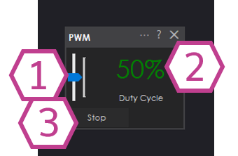
- 1. PWM Slider
- Drag this slider to set the PWM duty cycle for the selected digital port. Moving it higher increases the “average power” being delivered.
- 2. Duty Cycle Percentage Readout
- Shows the exact duty cycle value (0–100%). This is helpful when you want to repeat the same setting later.
- 3. Stop Button
- Immediately sets PWM to 0% (OFF). Use this as an emergency stop for anything driven by PWM.
Settings
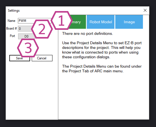
- 1. Name Field
- Give the skill a friendly name (for example: Left Motor Speed or Headlight Brightness). This is especially useful if you add more than one PWM Slider to the same project.
- 2. Board Drop-down
- Select which EZ-B (or I/O controller) you are using. Most projects use Board 0 unless you have multiple controllers connected.
- 3. Port Drop-down
- Choose the digital port where your device is connected (for example: D0, D1, D2, etc.). The PWM will be generated on this selected port.
How to Use PWM Slider (Step-by-Step)
-
Add the skill to your ARC project:
Project → Add Skill → PWM → PWM Slider -
Wire your device:
Connect your device to the correct controller input. Common examples:- Motor controller: Connect the driver’s Enable (or PWM input) to an EZ-B Digital port.
- LED: Connect the LED (with a resistor) so the digital port can switch it on/off rapidly.
-
Open the PWM Slider settings and select:
- The correct Board
- The correct Digital Port your device is connected to
-
Use the slider in the Main Window to change the PWM:
- Start at 0% and slowly increase to test your wiring safely.
- Watch the percentage readout to see the exact value you are sending.
- Press Stop to immediately turn the output OFF.
Common Uses
Control DC Motor Speed (via Motor Controller)
Connect the motor controller’s Enable/PWM input to a digital port, then use the slider to adjust speed. Higher duty cycle usually means faster motor speed.
Control LED Brightness
PWM can dim an LED smoothly. Use a resistor and increase the duty cycle to make the LED brighter.
Requirements
- An I/O Controller with digital ports that support PWM output.
- A properly connected device (motor driver, LED with resistor, etc.).
Video
Related Tutorials

Related Questions
Using Stepper Motors With ARC
Using Pwm's On Connection 3

Upgrade to ARC Pro
Become a Synthiam ARC Pro subscriber to unleash the power of easy and powerful robot programming