
Pulse Flash LED With PWM
Pulse Width Modulation is the method of having a digital port, which is only On or Off to have a varying output voltage. Use this approach to flash and LED with a pulsing effect.
Step 1
DC electricity works by having Positive and Negative. An LED is short for a Light Emitting Diode. A diode prevents current from flowing both directions. Diodes only allow current to flow in one direction, and they’re always polarized. A diode has two terminals. The positive side is called the anode, and the negative one is called the cathode.
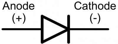
Current through a diode can only flow from the anode to the cathode, which would explain why it’s important for a diode to be connected in the correct direction.
Did You Know: Physically, every diode has some sort of indication for either the anode or cathode pin. Usually the diode will have a line near the cathode pin, which matches the vertical line in the diode circuit symbol.
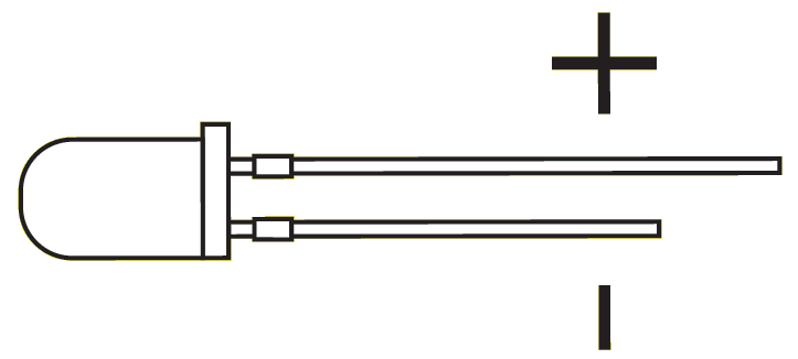
An LED has a physical indication of Anode and Cathode pins as well. LED stands for light-emitting diode, which means that much like diodes, they’re polarized. Find the longer leg, which indicates the positive, anode pin.
Connect an LED to port D0 of the EZ-B. In this example, we will provide power (+) to the LED from a signal pin of the EZ-B. The EZ-B will output +3.3 volts on the signal pin when it is in the ON state. The signal pin will respectively output GND when it is in the OFF state.
Connect the LED's Anode (+) wire to the signal (white) pin D0 of the EZ-B.
Connect the LED's Cathode (-) wire to the ground (black) pin D0 of the EZ-B.
The Code Use the ServoSpeed() command to apply a ramping speed to the PWM. The PWM command to set the brightness. The PWM essentially turns the state of the digital pin ON and OFF hundreds/thousands of times per second to produce the result of a "varying" voltage. The PWM range is between 0% and 100%, called the Duty Cycle.
The ServoSpeed() command will configure Ramping between two PWM duty cycles.
Add an EZ-Script control to your project, edit and paste this code...
# set the servo speed to 2
ServoSpeed(d0, 2)

:loop

# Set LED On
pwm(d0, 100)

# wait some time for the pwm to do its ramping thing
sleep(3000)

#set LED Off
pwm(d0, 0)

# wait some time for the pwm to do its ramping thing
sleep(3000)

goto(loop)
Tweak the Sleep() command time and the ServoSpeed() command time to see the different pulsing effects.

ARC makes everything "easy" -:)
And of course it's not working for ME... I took an LED and wired it to a spare extension cable that I had, I took this script and modified it to go into D12, and nothing's happening.
On the plus side, I guess I can count my blessings that trying this didn't make my EZ-B explode...
Hey Bob jut wanted to check a couple things, could the LED be plugged in backward? Did you double check you are on the right port and selected the right port on the EZ-B? Have you tried another port?
It's in the right port, and unless the Powers That Be have decided to switch things up and make the SHORTER end of the diode the positive end (a move I wouldn't put past them), no it isn't plugged in backwards. Changing ports didn't help either.
Bobsheaux
did you use a black/white wire to connect it on ezbv4 black and white ports?
Hi Bob the only LEDs that are sometimes unconventional are Red LEDs. The anode and cathode are reversed on some of them.
Make sure you are connected to the EZ-B when you use the PWM skill. You don't even need a series resistor in line with the LED because the EZ-Bv4 and IoTiny have them on board.
Here's a quick video I made for you to show it working.
Video.zip
Bobsheaux
can you try pwm(d12,0) first line and second pwm(d12,100)