
Hitachi-LG LDS 360-degree LiDAR driver streaming scans into ARC NMS for obstacle detection, SLAM use, Arduino hookup, config options and variables.
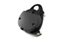
 Hardware Info
 Source Code
How to add the Hitachi-LG LDS Lidar robot skill
- Load the most recent release of ARC (Get ARC).
- Press the Project tab from the top menu bar in ARC.
- Press Add Robot Skill from the button ribbon bar in ARC.
- Choose the Navigation category tab.
- Press the Hitachi-LG LDS Lidar icon to add the robot skill to your project.
Don't have a robot yet?
Follow the Getting Started Guide to build a robot and use the Hitachi-LG LDS Lidar robot skill.
How to use the Hitachi-LG LDS Lidar robot skill
NMS Driver for the Hitachi-LG LDS 360-degree lidar. This robot skill connects to the Lidar and pushes the data into ARC's NMS (navigation messaging system) to be used with level 1 navigation viewers. To understand how this skill can be used, reference the NMS manual page.
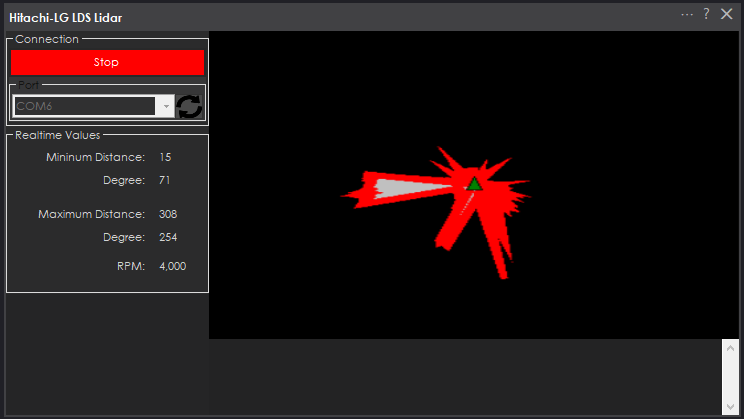
Screenshot
Configuration

1) BaudRate value The baud rate for communication to the USB serial adapter or Arduino. By default, the baud rate for the lidar should be 230400. However, some USB serial converters use different baud rates between the PC's USB port. The baud rate between the lidar and USB adapter must be 230400.
2) Offset Degrees value Correct the angle that the lidar is mounted
3) Advanced communication parsing checkbox Include debug information in the log window. This is only recommended if asked by Synthiam to help debug a communication issue. Otherwise, this will use a lot of resources.
4) Set variables with location data checkbox If you're not using the NMS, check this option. The global variables will be created for the scan data if this checkbox is checked.
5) Fake NMS Pose hint event checkbox The Better Navigator can use the Hector SLAM pose hint, which will not require a pose sensor. You can enable this option if you have The Better Navigator configured to use Hector as the pose hint. This will send a "fake" pose hint of 0,0 to the NMS so that the pose event will run after every lidar scan.
6) RTS Enabled checkbox RTS (Ready To Send) is an optional signal line for UART communication. Some USB adapters, specifically some Arduinos, may require this to be enabled. If your USB Serial adapter is not responding, you may need to enable or disable this option.
7) DTR Enabled checkbox DTR (Data Terminal Ready) is an optional signal line for UART communication. Some USB adapters, specifically some Arduinos, may require this to be enabled. If your USB Serial adapter is not responding, you may need to enable or disable this option.
NMS (Navigation Messaging System)
This skill operates in Level #3 Group #1 and publishes obstacle detection to the NMS. While some SLAM systems will attempt to determine the robot's cartesian position without telemetry, it is best to combine this skill with a Group #2 sensor.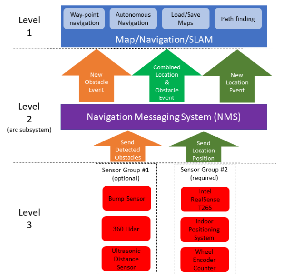
A recommended navigation robot skill is The Better Navigator, which uses the NMS data.
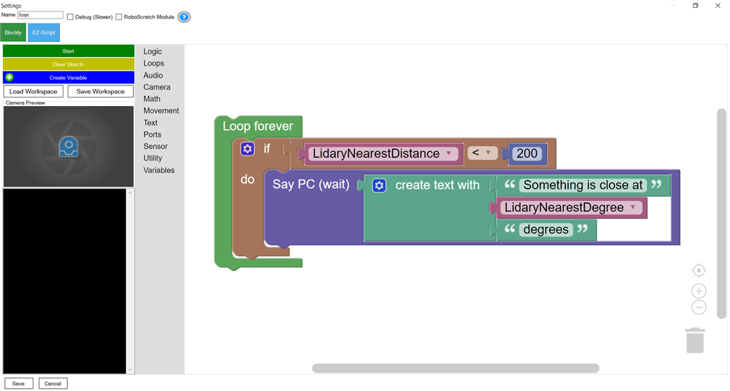
Program the LIDAR in Blockly Like all Synthiam controls, the Blockly programming language can be used. In the example below, the robot will speak when an object has come close to it. It will also speak the degrees of where the object was. To see this program in action, click HERE.
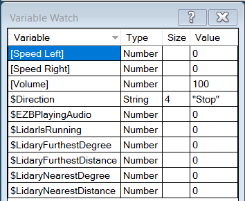
Variables You can view the variables this skill creates in the configuration menu of this control. The variables hold the most recent values of the lidar's minimum/maximum distance, degrees, and running status. Here is a list showing the variables using the Variable Watcher robot skill.
Arduino Sketch
There are two ways to connect to this lidar. You can use a standard USB<->UART converter, such as those on Amazon or eBay. Or you can use a 32u4-based Arduino board (i.e., Micro) to make your own USB<->UART converter. The 32u4-based boards are necessary Arduino versions because they support emulating USB HID devices, such as serial devices.Here is a simple sketch that can be used on a 32u4-based board...
void setup() {

   Serial1.begin(230400); // Init Hardware Serial port on pins 0 and 1
   Serial.begin(230400);  // Init Serial Port
}

void loop() {

  if (Serial.available())
    Serial1.write(Serial.read());

  if (Serial1.available())
    Serial.write(Serial1.read());
}
Wiring
GREY - Ground RED - +5 GREEN - RX (connects to TX on Arduino or USB Converter) BROWN - TX (connects to RX on Arduino or USB converter)Robotis USB <-> UART Converter
The Robotis version of this sensor may include their USB UART converter, which uses a CP210x chipset. The driver for Windows can be found by clicking here: CP210x_Windows_Drivers.zipVideos
Real-time SLAM mappingRoom Mapping
Near Object Detection

Also, make sure the sensor is getting adequate power.
Fist thing I checked.. Getting 5.14v although I didn't look at how many milliamps it is getting. I'll try with a different computer with a powered USB hub in the morning. I'll also try with my Realsense unplugged. Could be that this little tablet can't put out enough juice.
The realsense uses a lot of bandwidth - which surprised me. At first i thought all the processing was done in the sensor. But no....
So make sure the usb ports aren't shared via an onboard hub. Try different ports between the lidar and realsense.
Well, the good news (not really when I think about it) is that my cable is fine. The Lidar works perfectly on another computer. Works better in the USB 3 port instead of the USB 2 port of the tablet, but I suspect the RealSense won't be happy with USB 2.
It might be better if I separate the power and put a voltage regulator so I can run the motor power from the EZ-B instead of the USB port, but the real difference I see is that in the other computer I can set the com port to much higher speed in device manager for the cable, so pretty sure that even thought it says it is USB 3, the tablet may not actually be performing at that level.
If I am going to continue to use Roli as my test bed, I am going to need to figure out how to provide 12 volts to the computer because unlike the tablet, it doesn't have it's own power supply and runs at 12v. The computer itself will just fit on top of Roli, but not sure what I can do for power. I may need to build a trailer for a battery, at which point, maybe I should just be scratch building anyway. I just like how using EZ-Bits I can quickly change configurations. Also, without a screen, it will need to run headless, but that was the plan for the big computer anyway. If I had on board screen at all, it was probably going to be another computer running Anydesk or another remote control app.
Oh well, getting there one step at a time. May be a few weeks before I figure out how to make this all work and get any additional components I need (heck, I don't even have a 12 v charger because my original plan was to use 24 volts and Wheelchair motors, but I have been thinking smaller and slower lately, and my 24v SLA is actually 2 12v batteries wired together, so I can easily split them... Of course, they are way too heavy for Roli to tow, so again, I may need to scratch build platform just for the navigation testing. I have a couple of 12v motors, and plenty of plywood and MDF. Need wheels... final build I want treads, but that can wait. so main items now I think are wheels and a charger).
Alan
I power the rock pix for about 10 hours with this: https://www.amazon.ca/gp/product/B07YPSZKSY/ref=ppx_yo_dt_b_asin_image_o05_s00?ie=UTF8&psc=1
here’s a pic of the setup. The lidar isn’t being used right now because I have an intel realsense array. But that battery pack is amazing.
I have poking around Amazon for similar with 12v output. That will probably be the easiest, and they don't look too expensive.
I just recently got one with 19.4 V volts and 29.4 as well as a USB A and USB C PD to power my guitar amp and as well as extra juice for my laptop. If I had known I would have found one that also does 12v.
Alan
If you require 12v, i use this for my fish finder: https://www.amazon.ca/Talentcell-Rechargeable-6000mAh-Battery-Portable/dp/B00MF70BPU/ref=sr_1_11?dchild=1&keywords=12v+battery+pack&qid=1617069244&sr=8-11
I looked at that one. Good price, but I decided on this one because it will serve other purposes when this test platform project is done and I move everything into a permanent build:
https://smile.amazon.com/dp/B074PQBRJV/ref=cm_sw_r_cp_apa_fabc_PCV52EQQG104F1428A8V