
Read TTL digital input from an ARC I/O port; real-time red/green status for low (0V) or high (+3.3/5V), selectable board/port and read interval.
How to add the Read Digital robot skill
- Load the most recent release of ARC (Get ARC).
- Press the Project tab from the top menu bar in ARC.
- Press Add Robot Skill from the button ribbon bar in ARC.
- Choose the Digital category tab.
- Press the Read Digital icon to add the robot skill to your project.
Don't have a robot yet?
Follow the Getting Started Guide to build a robot and use the Read Digital robot skill.
How to use the Read Digital robot skill
The Read Digital robot skill shows the current ON/OFF state of a digital input pin on your I/O Controller.
It is a graphical version of the ARC script command ReadDigital().
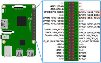
Digital inputs use TTL logic, which means the controller reports:
- LOW = about 0V (often considered “OFF”)
- HIGH = about +3.3V or +5V (depends on your I/O Controller; often considered “ON”)
ReadDigital() inside an ARC script.
Main Window
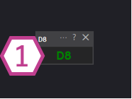
1. Digital Status Indicator
This indicator changes color based on the voltage detected on the selected digital input port:
- Black — No I/O Controller is connected (or ARC is not connected to the board yet).
- Red — The port is reading LOW (near 0V).
- Green — The port is reading HIGH (near +3.3V or +5V, depending on the controller).
Settings
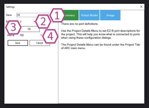
- Smaller number = faster updates, more frequent polling.
- Larger number = slower updates, less CPU/communication usage.
If you’re unsure, start with a moderate interval (for example, 100–250 ms) and adjust as needed.
How to Use Read Digital (Step-by-Step)
- Add the skill to your project: In ARC, go to Project → Add Skill → Digital → Read Digital.
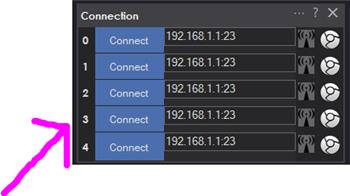
- Connect to your I/O Controller: Make sure ARC is connected to your board. Before connecting, the indicator will remain black.
-
Open the skill settings and select:
- Board (the controller you are using)
- Port (the digital input where your sensor/switch is wired)
- Interval (how often you want updates)
- Watch the indicator on the main window: Toggle your switch or trigger your sensor and confirm the indicator changes between red (LOW) and green (HIGH).
When Should I Use This Skill?
Good for
- Checking if your wiring is correct
- Testing a sensor before writing scripts
- Learning what HIGH and LOW look like in real time
- Quick troubleshooting (is the port changing?)
Not a replacement for
- Using
ReadDigital()in scripts for robot logic - Event-driven behaviors (where scripts react to input changes)
- Projects where minimizing polling/overhead is important
Requirements
- An I/O Controller that supports digital input ports.
- A device that provides a digital output (LOW/HIGH), or a switch wired to produce LOW/HIGH.
Related Tutorials
Related Hack Events

Related Questions
Ezbpi Server - Access To The Pi Gpios
More DIO Ports Required

Upgrade to ARC Pro
Join the ARC Pro community and gain access to a wealth of resources and support, ensuring your robot's success.
Can this actually detect a high value 3.3v or 5v and a low value 0v on a typical output or does it have to be the ADC? I noticed you are using D8. Could you explain how it's doing this? Does it need a separate device to interpret it, could give an example of the device?
Hi @Automation Man
I can confirm that DigitalRead does indeed detect a high signal (3.3V for EZ-Bv4 which is also 5V tolerant) and low signal.
I have read that the threshold for a high signal has to be above 1.88V and for a low voltage it has to be under 1.23V for STM32 chips.
The skills uses the Digital I/O pins in the "I" (input configuration) and reads the voltage on the D8 (or otherwise setup) Digital pin to see if it's either under 1.23V (low - red) or above 1.88V (high - green).