
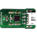
Reads MPU6050 gyro, accelerometer and temperature via I2C, initializes and returns data on-demand to EZ-Script variables using ControlCommand RunOnce
How to add the MPU6050 Accelerometer Gyro Temperature robot skill
- Load the most recent release of ARC (Get ARC).
- Press the Project tab from the top menu bar in ARC.
- Press Add Robot Skill from the button ribbon bar in ARC.
- Choose the I2C category tab.
- Press the MPU6050 Accelerometer Gyro Temperature icon to add the robot skill to your project.
Don't have a robot yet?
Follow the Getting Started Guide to build a robot and use the MPU6050 Accelerometer Gyro Temperature robot skill.
How to use the MPU6050 Accelerometer Gyro Temperature robot skill
- Accelerometer (detects movement/tilt by measuring acceleration)
- Gyroscope (detects rotation rate)
- Temperature sensor (reports the chip’s temperature)
Before You Start (Beginner Checklist)
-
Hardware connected: Plug the MPU6050 EZ-Bit into the EZ-B’s I2C port.
Important: I2C devices require the correct wiring. If the sensor is not connected properly (or not connected at all), the EZ-B v4 can lock up when a read is attempted.
- Add the skill to your ARC project: Add the MPU6050 control/skill to the ARC workspace.
- Have a way to run a script: Add an EZ-Script control where you will place the example code below.
Key Concept: INIT First, Then Read On Demand
This skill does not continuously read the sensor automatically. You must:
- Run
Initonce to initialize the MPU6050. - Run
RunOnceeach time you want fresh sensor values.
Init, the MPU6050 will not return data.
If you call RunOnce repeatedly, the variables will be updated each time.
Where the Sensor Data Goes (EZ-Script Variables)
Each time you read the MPU6050, this skill updates a set of EZ-Script Variables. The exact variable names can vary by version/configuration, so the easiest way to see them is:
- Click the Config button on the MPU6050 control.
- Look for the list of variables that the skill updates.
- Use the Variable Watcher to watch those values change live.
Example: Read the MPU6050 Every 100ms (10 Times/Second)
The script below initializes the sensor once, then loops forever. Every loop it:
- Requests a new reading from the MPU6050 using
RunOnce - Waits
100milliseconds - Repeats
ControlCommand("MPU6050", Init)

:loop

ControlCommand("MPU6050", RunOnce)

Sleep(100)

Goto(loop)
Sleep(250)).
If you want faster updates, decrease it (example: Sleep(50)). Very fast loops can overwhelm your project if you don’t need them.
Troubleshooting
- EZ-B v4 locks up when running the script: This usually means the MPU6050 is not connected correctly, not powered, or not on I2C. Disconnect power, check the I2C connection, then try again.
-
Variables are not changing: Make sure you ran
Initfirst, and that the loop is callingRunOnce. Also confirm you’re watching the correct variables in the Variable Watcher. - Data looks “noisy” or jumpy: That is common with IMU sensors. Consider averaging values in your script or reading at a steadier rate.
Example Project (Video Mention)
A working example is shown in the video using the JD project with the MPU sensor. You can find it in the EZ-Cloud as: JD With MPU6050 Accelerometer.
How It Works (Learn More)
Want to understand IMU sensors (accelerometer + gyro) in more detail? This is an excellent beginner-friendly article: https://www.starlino.com/imu_guide.html

Question can we also add offsets to the MPU skill so it can be calibrated like you can in the Arduino code? See Below:
I have used this to help adjust the MPU in Arduino code using the MPU6050_6Axis_MotionApps20.h lib.
This would allow you to zero/calibrate the gyro. That has been used within your project as every MPU6050 is not the same.
You can modify the arduino code to do that. Or you can modify the values in ARC. You can do this with math functions, such as a + (addition) or - (subtraction)
For example, if you have a variable $AccelX, you can add to it by doing this.
$AccelX = $AccelX + 2
That will add the value of 2 to the previous value in the variable.
I agree a DJ that can be done but it would be nice to set it and forget it so to speak. You know work smarter not harder LOL
I understand - it's a lot of resources (costly) to have programmers spend a workday modifying a robot skill so it can add and subtract a number
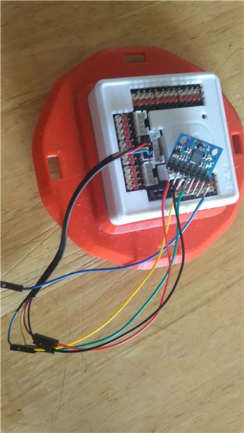
@Jeremie, Well I finally got to the point where I hooked up the MPU6050 with the pull up resistors like you said but it starts out and after a short time the red LED on the ezb4 stays on and then the ezb4 connection disconnects so now what can I do to address this?
Hello @smiller29 that means you’re getting communication lock up. Try polling the sensor slower and see if that helps or you can adjust the pull-up values. There are plenty of different MPU6050 modules out there so I can’t really say what will work exactly for you. 330 ohm pull-ups worked with my modules.
You’re always welcome to post code and pictures if you’d like.
@Jeremie the loop has a sleep 2000 in it and does not help what do you think I should bump the pull up resistors to?
Hello again @smiller29,
When using DIY electronic modules with I2C sometimes some tinkering around needs to be done.
I really don't have a good idea of what your setup looks like. Are your I2C wires long? Which MPU-6050 module are you using? Have you tried changing the pullup resistors to a different value? Is there an LED on the MPU6050 module that tells you the 3.3V power is reaching the module? Are you powering the module with 3.3V before or after the voltage regulator?
I would try the following: shorten the wires, check your supply voltage to the module, and if all looks good then try bringing the pull-ups down to the next standard resistor value (likely 220 ohm).