
Esp32 by Espressif
Firmware
ESP32Plus for Synthiam ARC enables ESP32 robot control with audio streaming, ESP32-CAM passthrough, PCA9685 16-servo I2C control and UART expansion.
Convert ESP32 DOIT DevKit v1 into an EZ-B for Synthiam ARC: WiFi bridge with servo and I/O support for compact robotics projects.
ESP32 as Synthiam ARC EZ-B controller using PCA9685 over I2C for 16-channel 12-bit servo/PWM control and expanded I/O
The ESP32 is a small, low-cost microcontroller without a camera onboard. Think of a microcontroller as a tiny computer whose job is to control hardware. It can:
- Read inputs (buttons, distance sensors, switches, analog modules, etc.)
- Control outputs (LEDs, relays, motors/servos using PWM, buzzers, etc.)
- Communicate over Wi‑Fi (and Bluetooth, though ARC connection is typically Wi‑Fi)
The ESP32 is also generic hardware—many companies sell boards based on the same ESP32 chip. You may see board names like DevKit v1, DOIT, NodeMCU‑32S, etc. These boards can look slightly different, but the setup concepts in this guide are the same.
When you install the Synthiam ESP32 firmware onto your ESP32 board, it will behave like an EZ‑B controller. That means Synthiam ARC can connect to it and control: digital I/O, PWM/servo signals, serial ports, and more—similar to how ARC works with other EZB-type controllers.
- ESP32 = the chip family (the “brain”).
- DevKit / DOIT / NodeMCU = different boards built around the ESP32 chip.
- GPIO = the pin names printed on the board (example:
GPIO2,GPIO23). - ARC ports (D0–D23) = the port names ARC shows you. These map to specific ESP32 GPIO pins.
2, 4, 12–19, 21–23, 25–27, 32–33
Why does this matter? Some ESP32 pins are used during boot (startup) or have special functions. Using the wrong pins can cause:
- jittery/unstable servo movement
- random reboots/resets
- the ESP32 failing to boot until you disconnect the servo
- Use a separate regulated 5V supply for servos (with enough amps for your servo count).
- Critical: connect the servo power supply GND (−) to the ESP32 GND so they share a common ground.
What You Need (Beginner Checklist)
-
An ESP32 breakout board
Examples: DevKit v1, DOIT, NodeMCU‑32S. (Not ESP32‑Cam.)
-
USB cable that supports data
Some cables are “charge-only” and will power the board but cannot upload firmware.
- Windows PC (for Synthiam ARC)
- Synthiam ARC installed
-
Synthiam ESP32 firmware installed on the ESP32
This firmware is what makes the ESP32 act like an EZB controller.
-
A Wi‑Fi plan (choose one):
- AP Mode: your PC connects directly to the ESP32’s Wi‑Fi (no router required)
- Client Mode: the ESP32 joins your home/office Wi‑Fi router
-
If using servos:
- Regulated 5V power supply with enough amps
- Wires to connect servo GND to ESP32 GND
-
Optional but helpful:
- Breadboard and jumper wires (makes beginner wiring much easier)
- A basic multimeter (helpful for checking 5V/3.3V and ground connections)
Video Tutorial
This video shows a step-by-step walkthrough of connecting an ESP32 to ARC and confirming communication. If something doesn’t work, the most common causes are: wrong Wi‑Fi mode, wrong IP address, incorrect firmware, using a charge-only USB cable, or power/wiring problems.
Wi‑Fi Modes (How ARC Connects)
The Synthiam firmware supports two Wi‑Fi connection modes. Pick the one that matches how you want to use your robot. In both modes, ARC communicates with the ESP32 over the network.
AP Mode (Access Point / Hotspot)
In AP Mode, the ESP32 creates its own Wi‑Fi network (similar to a phone hotspot). You connect your PC/tablet to that Wi‑Fi, then ARC connects to the ESP32.
- Best for: quick testing, portable robots, demos, no router available.
- Gotcha: your PC may lose Internet while connected to the robot Wi‑Fi.
- Gotcha: Windows may auto-switch back to your normal Wi‑Fi, which disconnects ARC.
Client Mode (Join Your Router)
In Client Mode, the ESP32 connects to your existing router Wi‑Fi like a normal device. ARC connects to the ESP32 using its IP address on that network.
- Best for: longer range, multiple computers/tablets watching, keeping Internet access.
- Gotcha: you must know the ESP32’s current IP address.
- Gotcha: “Guest Wi‑Fi” often blocks devices from seeing each other.
- Connect the ESP32 to your PC by USB.
- Open the Arduino IDE (or another serial terminal program).
- Go to Tools > Serial Monitor.
- Set baud rate to
115200. - Reset the ESP32 (press EN or unplug/replug) and read the messages.
- Baud rate is the serial “speed.” If you see random symbols, set it to
115200. - If the ESP32 never shows a valid IP in Client Mode, double-check your Wi‑Fi name/password and whether your router blocks new devices.
Connecting from ARC (Beginner Steps)
-
Plug the ESP32 into your PC with USB.
You should see a power LED. If nothing lights up, try a different cable or USB port.
-
Confirm the firmware is installed.
If the board doesn’t behave as expected, re-flash the Synthiam ESP32 firmware.
-
Decide your Wi‑Fi mode: AP or Client.
If you’re unsure, AP Mode is usually easiest for first-time testing.
-
Make sure your PC is on the correct Wi‑Fi network.
- AP Mode: connect Windows Wi‑Fi to the ESP32’s Wi‑Fi network.
- Client Mode: connect Windows Wi‑Fi to the same router network the ESP32 joined.
-
Open ARC and add the ESP32/EZB connection that matches the Synthiam firmware.
Then enter the IP address (Client Mode) or connect while on the ESP32 Wi‑Fi (AP Mode).
-
Connect and verify communication.
If ARC shows “Connected,” you’re ready to control pins and add skills.
-
Test with something simple:
- Toggle a digital output (e.g., LED module on a GPIO pin)
- Move one servo on a recommended “safe” pin (with proper external 5V servo power)
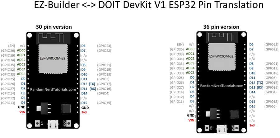
Port Configuration (ARC D0–D23 vs ESP32 GPIO)
In ARC, digital ports are often shown as D0–D23.
On ESP32 boards, the physical pins are labeled GPIO (example: GPIO2, GPIO4, GPIO23).
These do not run in perfect order down the board, and some GPIO numbers may not exist on your particular ESP32 breakout.
D4, you must wire your device to the correct GPIO that matches D4
using the mapping of the firmware. In other words: ARC port name and board pin label are different systems.
Pins labeled TX and RX are used for serial communication (UART). Many boards connect these to the ESP32’s main serial port (often called UART0 / Serial0), which is also commonly used for USB programming/serial logs.
2, 4, 12–19, 21–23, 25–27, 32–33
Quick Wiring Basics
- GND to GND: Most sensors (and all servo signal systems) need a shared ground.
- Signal to GPIO: The control/data wire goes to the GPIO pin you select in ARC.
- Power to the correct pin: Many sensors use 3V3; some modules use 5V/VIN.
- VCC = power in
- GND = ground
- OUT / SIG / DATA = signal to a GPIO pin
Voltage Levels (Very Important)
- ESP32 GPIO logic is 3.3V. A “HIGH” signal is about 3.3V.
- Some modules are powered from 5V but still output a safe 3.3V logic signal (depends on the module).
- If a device outputs 5V into an ESP32 GPIO pin, you may need a level shifter (or voltage divider) to avoid damaging the ESP32.
Servo Wiring (Typical)
Usually white/yellow/orange
Usually red
Usually brown/black

Wiring was getting too messy (even for me) so I created a little ESP32 servo shield. In hindsight I really don’t need the FTDI as I won’t reprogram it unless a new firmware comes out so I think I will order just the ESP chips from China and make some smaller shields just for servo control.
That's a great idea! Looks good with the sticker labels!
Very cool work.
Small problem with ESP servo calibration and degrees of movement. Take a HDD servo connect to an ESP and press center and it is about 10 degrees off. Now plug it into a EZB press center Perfect.
OK recalibrate for ESP. Now add servo control and move it to 1 degree it should be at 90 degrees to servo motor but it is about 45 degrees. Now move it to 180 degrees and it is only at about 135 degrees.
now move back to 0 and press release and it will move back to 135 degrees now move servo by hand to 0 and press release again this time it moves back to 135 but doesnt release
using latest ESP firmware and port D5
That’s the esp32 servo firmware for ya. All of the arduino servo libraries are off a little. They weren’t written that well. Might want to take a look at other servo libraries to try instead of the one I choose. I think it choose that one because it was the highest recommended.
Take a look at this, I’m not sure what it means "different channels" vs "same channel". I often wonder if the esp32 has enough clock left over after the tcp stack to run timers in real-time: https://www.arduino.cc/reference/en/libraries/esp32servo/
Wanna try a new firmware for me? I updated the servo library to the latest - see if this helps. Let me know if it works before I update it on the website firmware list: EZ-ESP32.zip
went to bed with a broken servo, woke up to a working servo. Nice thank for the quick turn around. you still have to recalibrate (although i guess I could use an offset with my bots that use them) and release doesn't work but I get 180 degrees and it is a lot snappier, the old driver was a bit grindy.
I think the ESP has a lot of promise as a controller. There are a lot of things that work with arduino like LIDAR etc and having a single $5 controller that does a lot of things with ARC would be great.
I am sure the new ESP32-S3 will solve all the performance issues as well
https://www.espressif.com/en/news/ESP32_S3