
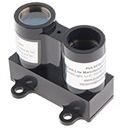
Laser Lidar-Lite ARC control reads distance, velocity and signal strength (0-40m+) via EZ-B v4 i2c, setting EZ-Script vars for robotics
How to add the Lidar-Lite Laser Module robot skill
- Load the most recent release of ARC (Get ARC).
- Press the Project tab from the top menu bar in ARC.
- Press Add Robot Skill from the button ribbon bar in ARC.
- Choose the I2C category tab.
- Press the Lidar-Lite Laser Module icon to add the robot skill to your project.
Don't have a robot yet?
Follow the Getting Started Guide to build a robot and use the Lidar-Lite Laser Module robot skill.
How to use the Lidar-Lite Laser Module robot skill
The Lidar-Lite is a laser-based distance sensor that connects to the EZ-B using the I2C bus. In ARC, the Lidar-Lite Robot Skill lets you request a reading from the sensor and then places the results into EZ-Script variables that your project can use.
ControlCommand() (example below).
Lidar-Lite modules are often used for robotics, drones, and general sensing. Depending on your specific Lidar-Lite model and the target surface, it can measure from very close distances out to long range (often quoted as 40+ meters under ideal conditions).

1) What you need
- EZ-B supporting i2c capability
- Lidar-Lite sensor module (third-party hardware)
- EZ-B I2C Peripheral Cable (25cm) (or equivalent I2C wiring)
-
5V power for the Lidar-Lite
- Many Lidar-Lite units require a stable +5V.
- You may need an Inline 5V regulator (30cm) or another proper 5V source.
- Soldering tools/supplies (because the Lidar-Lite typically does not plug directly into the EZ-B I2C cable)
2) Connecting the hardware (beginner overview)
Your Lidar-Lite can connect to any ezb i2c port. I2C uses four connections: GND, +5V, SDA, and SCL.
Typical I2C wiring
- GND (ground) from Lidar-Lite → GND on EZ-B
- VCC / +5V from Lidar-Lite → a stable +5V supply (often via a regulator)
- SDA from Lidar-Lite → SDA on EZ-B I2C
- SCL from Lidar-Lite → SCL on EZ-B I2C
If the ARC control tries to read the Lidar-Lite while it is not connected (or wired incorrectly), the EZ-B may lock up.
3) Adding the Lidar-Lite skill in ARC
- Open your ARC project.
- Add the Lidar-Lite Robot Skill/control to your workspace.
- Click the control’s Config button and select the I2C port you plugged the sensor into.
- In the same Config screen, note the EZ-Script variables that the control updates (these variable names are shown in the control’s configuration).
This skill writes sensor results into EZ-Script variables (for example, a distance variable such as
$lidar).
The exact variable list is shown in the control’s Config window.
4) Reading the sensor (how it works)
This control does not continuously stream data. Instead, you request a single update using:
ControlCommand("Lidar Lite", RunOnce).
Each time you run that command, ARC queries the sensor once and updates the skill’s variables.
To verify that your data is changing:
- Open ARC’s Variable Watcher to watch variables update in real time.
- Or use
print()inside an EZ-Script to display the value.
5) Example EZ-Script (polling every 100ms)
The script below tells the Lidar-Lite skill to run once, prints the distance variable, waits 100 milliseconds, and repeats. Make sure your Lidar-Lite control is named "Lidar Lite" in ARC (or change the name in the script to match your control).
:loop

ControlCommand("Lidar Lite", RunOnce)

print("Distance: " + $lidar)

sleep(100)

goto(loop)
$lidar in the Lidar-Lite control configuration,
replace $lidar in the script with the actual variable name shown in the control’s Config.
6) Troubleshooting checklist
- EZ-B locks up: Stop the script/control and re-check wiring. This often happens when the control is polling but the sensor is missing or miswired.
- No changing values: Confirm the correct I2C port is selected in the control Config.
- Value is always 0 or blank: Confirm the sensor has proper 5V power and a common ground with the EZ-B.
- Script prints “Distance” but not a number: Verify the variable name in Config and watch it in the Variable Watcher.
- Intermittent readings: Reduce polling rate (try
sleep(250)) and ensure power is stable.
Synthiam does not manufacture this device, and EZ-Robot/Synthiam is not responsible for third-party hardware operation. For specifications, supported modes, and hardware behavior, consult the Lidar-Lite manufacturer documentation.

I think this would be a quality device to have It only would need to scan once and then I could evaluate the data. Is there a manual so that I could look it over and see how it's actually working. Is it assigning a value in a cartesion coordinate system etc. or is it in pixel scenario for the variables?
Wondering why the I2C on the tiny does not match the typical I2C pinout. Is this a typo or has this been done to
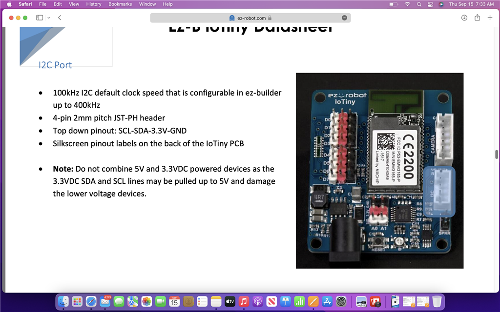
use just your I2C devices? Just need to know for sure what it is. Trying to get the lidar working and noticed this discrepancy.Synthiam doesn’t make the iotiny or any hardware. The manufacturer of that product is ezrobot.
Also, there is no standard for i2c connections. The website from that screenshot is just some random website from some other random product. Read more about i2c protocol here: https://en.m.wikipedia.org/wiki/IC
Ok didn't know that. I would have thought everyone would have agreed to a standard. I did check the voltage on the pinouts of the IO tiny and it is showing 3.3 v on one end and ground on the other which does not match the data sheet.
@Automation Man Sometimes if you measure the SDA or SCL line it will be held high to 3.3V. The Pinout is correct, see the silkscreen on the back of the IoTiny. The top-down pinout is SCL-SDA-3.3V-GND, just as the datasheet says.
As @DJ mentioned, there isn't a standard pinout for I2C devices, we decided to go with the pinout of one of the most popular I2C products back when we were developing the board which was the BlinkM standard.
To hook up to the LIDAR lite to an IoTiny you'd likely need an I2C logic level converter, but even then I believe that sensor was a bit finicky with pullup resistors and line capacitance so it may be a bit tricky to dial in. You also need 5V going to the sensor so you would need a 5V regulator attached to it coming from the Vin of the IoTiny. It is possible to use a resistor voltage divider for logic level conversion but that requires a bit of DIY knowledge. I don't have one of these sensors to test with so I can't really give you a 100% wiring diagram that will work.
The price point for these sensors is pretty high compared to a spinning 360-degree LIDAR sensor. I'm not sure I would recommend using the LIDAR lite when you can get a more power LIDAR for around the same price.
Thanks for the explanation and I should have flipped it over myself. I want to have both the singular and the 360 degree available in my personal toolbox for different applications. Is there a skill or a 360 variables table to handle the different distances-that would be very helpful because then you could analyze it all and be very specific on what you want to do with the data. On one of the videos that I saw it was very data intensive and will not work. Here is an example of what I'm trying to accomplish- 360 lidar scans (but only use 50 degrees of it) over the top of a 1x6 wood board (only need one time scan) so you need to know the leading edge and the falling edge as compared to the degree then divide it up and get to the center. I have been able to get this to work with infra red and feedback but infra red data bounces around way too much. If you know of a lidar and 360 lidar that work right out of the box or with a bit of desoldering to flip the wires that would be a big help. A quick video describing how you got it to work would be great.
I wouldn't use a 360-degree lidar for finding the edge of the wood or something because it won't be accurate enough, IMO. The challenge you'd run into is the angle at which it would be scanning. It spins and scans outward from the sensor, so you'd have to visualize that in your mind.
The closer the 360 sensor is, the less of the angle you'll detect. The higher the sensor is, the more you'd detect but increase error from a distance.
So, either way, you look at it, a 360-degree sensor won't work for your application.
What I would recommend would be an IR or single laser distance sensor. But use a short-distance version because that would give you the edge, and you'd need to slide over it.
Or, you could have the object on a black surface and use a camera above it to get the shape. A statically mounted camera would give you the object's rectangle as a variable. If the background is black and the object is lighter, that would make detecting it much better.
Makes sense that a black background helps and will keep that in mind. Was planning to be about 15" away and then have the 360 take a scan, evaluated the math and then go to center. For the singular one swing the arm over it evaluate per degree rotation, do the math and then go to center. But I can't get the singular one working and the 360 is on order. Having a bank of variables already made would help. I haven't looked into navigation skill yet but doesn't that have something similar for variables built in to handle the pixels? I thought both types will give you a value for distance. If x value is less than 1/2" from one to another rotational degree that will be your leading edge and if x value is greater than 1/2" that will be your falling edge. Need to just have feedback for rotational angle to make it all work.