
Balancing controller for Sainsmart v3 (and compatible) robots: PID tuning, real‑time telemetry, angle offset, movement and calibration via ARC.
How to add the Inverted Pendulum robot skill
- Load the most recent release of ARC (Get ARC).
- Press the Project tab from the top menu bar in ARC.
- Press Add Robot Skill from the button ribbon bar in ARC.
- Choose the Movement Panels category tab.
- Press the Inverted Pendulum icon to add the robot skill to your project.
Don't have a robot yet?
Follow the Getting Started Guide to build a robot and use the Inverted Pendulum robot skill.
How to use the Inverted Pendulum robot skill
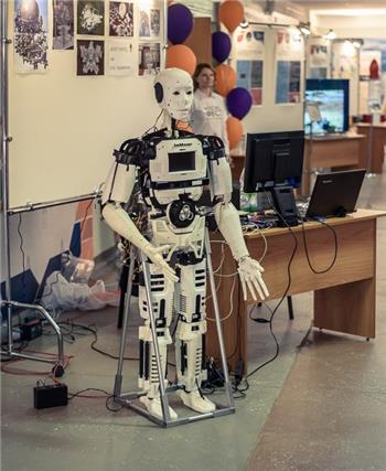
The inverted pendulum skill is designed to be used with the Sainsmart v3 balance robot but technically you can use the Sainsmart hardware, combined with ARC, to balance any robot. You'll just need some patience to tune the PID values. In order to use this skill you'll have to install the custom EZB firmware onto the Sainsmart robot's Arduino Mega and connect it to ARC.
Main window
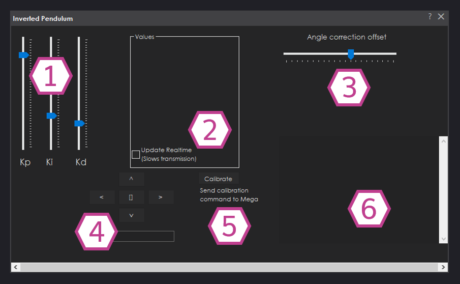
1. PID Gain Value Sliders These sliders adjust the proportional, integral, and derivative (Kp, Ki, and Kd) values that are used for the closed loop balancing algorithm.
2. Values Display & Update Realtime Checkbox The Kp, Ki, and Kd values are displayed here as well as Omega, Angle, Distance, encoder values, angle offset, and speed values. The Checkbox is used for showing realtime values if needed.
3. Angle Correction Offset Slider Correct the angle of your balancing robot with this slider.
4. Movement panel This panel allows you to move the balancing robot, forward, reverse, left and right.
5. Calibrate Button This button sends the Calibration command to the Arduino Mega.
6. Status Display This displays communication between ARC and the Arduino Mega.
How to Use Inverted Pendulum
Download the EZB firmware onto the Sainsmart Balancing robot's Arduino Mega.
Add the Inverted Pendulum Skill to your ARC project (Project -> Add Skill -> Movement Panels -> Inverted Pendulum).
Connect the Arduino Mega's COM port to ARC with a USB cable or Bluetooth.
Push the Calibrate button then start adjusting the sliders in the Inverted Pendulum Skill until you have optimal balancing. Adjust Kp, then Kd, and then Ki. Note that Kp is a usually higher in value and Kd is a very low value.
Video
Requirements
You will have to program the EZB firmware onto the Arduino Mega, located on the hardware page, in order to use this skill.Resources
The hardware for this skill can be found here: https://synthiam.com/Docs/Hardware/SainSmart-Balance-RobotHere is the Inverted Pendulum firmware for the Arduino Mega: https://synthiam.com/uploads/imagesrc/EZ-Mega-v1_Balance_Robot-636848728401310251.zip
The tutorial for installing the EZB firmware onto an Arduino Mega is here: https://synthiam.com/Community/Tutorials/Connecting-Arduino-to-EZ-Builder-17526
*Note: This skill is in beta stages


https://synthiam.com/Hardware/Hardware/17552
Link does not exist.
Fixed URL. I'll also have that old URL redirected because there's a ton of content posting to that old url that wasn't updated. Thanks for letting me know
Sure DJ, happy to help.
Problems connecting skill to Arduino error message: Connected device to EZ-B index #0 does not support the required capability. Field not found: 'EZ_B.Firmware.XMLFirmwareSimulator.CAP_INVERTED_PENDULUM_V1'.
The baud rate in the sketch is set to 115200 as is the baud rate in the EZ-B. The firmware id = 9
// The firmware version that is reported to ARC to notify of capabilities #define _FIRMWARE_ID 0x00000009
// The communication baud rate #define _BAUD_RATE 115200
This is my first attempt with Arc. Is there a way to test the communication to the arduino from the arduino serial monitor?
You got that error because it’s not the correct firmware. The capability for inverted pendulum isn’t supported, says the error
The correct firmware is posted above
Thanks for the suggestion. However I downloaded the firmware from the above location. file name: EZ-Mega-v1_Balance_Robot-636848728401310251.zip file size: 65,776 bytes
The firmwareID in the source code is: #define _FIRMWARE_ID 0x00000009
I have reduced the baud rate on both the Arduino and in the connection dialog. With no improvement. I do not get a connection if the baud rates are not aligned.
Is there a way to get the commands send by the Skill to the Arduino? So i can simulate that with the Arduino Serial Monitor.
PS. I added a blinker to main loop of the code to see if the code is running on the mega, which it is.
Here the output from the Debug Log
It shows it’s connected. The thing about arduino is there’s only one usb port. So you can’t use the serial monitor and connect at the same time. It’s one or the other.