
Display ADC port voltage and 0-255 linear values (0-3.3/5V); configurable board/port, units, multiplier and sample interval.
How to add the ADC Value robot skill
- Load the most recent release of ARC (Get ARC).
- Press the Project tab from the top menu bar in ARC.
- Press Add Robot Skill from the button ribbon bar in ARC.
- Choose the ADC category tab.
- Press the ADC Value icon to add the robot skill to your project.
Don't have a robot yet?
Follow the Getting Started Guide to build a robot and use the ADC Value robot skill.
How to use the ADC Value robot skill
The Read ADC robot skill displays the live voltage and numeric value from a specified EZ-B ADC (Analog-to-Digital Converter) port. This skill is ideal when you need precise numeric readings rather than a graphical display.
An ADC (Analog-to-Digital Converter) allows the EZ-B to measure a changing analog voltage from a sensor and convert it into a digital value ARC can use. EZ-B ADC ports measure voltages from 0V up to the controller’s TTL High voltage (typically 3.3V or 5V, depending on your controller configuration).
ARC converts this voltage into an 8-bit linear value ranging from 0 to 255:
- 0 = 0 volts
- 255 = TTL High (3.3V or 5V)
- Intermediate values are linearly proportional to the measured voltage
Main Window
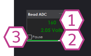
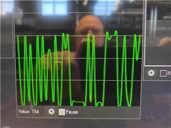
1. Linear Value Readout
Displays the ADC value as a linear number between 0 and 255. This value is directly proportional
to the input voltage measured on the selected ADC port.
2. Voltage Readout
Displays the calculated analog voltage in VDC. This value represents the actual voltage
measured at the ADC input based on the EZ-B TTL High reference.
3. Pause Checkbox
When checked, ADC sampling is paused and the displayed values remain frozen. Uncheck to resume live updates.
Settings
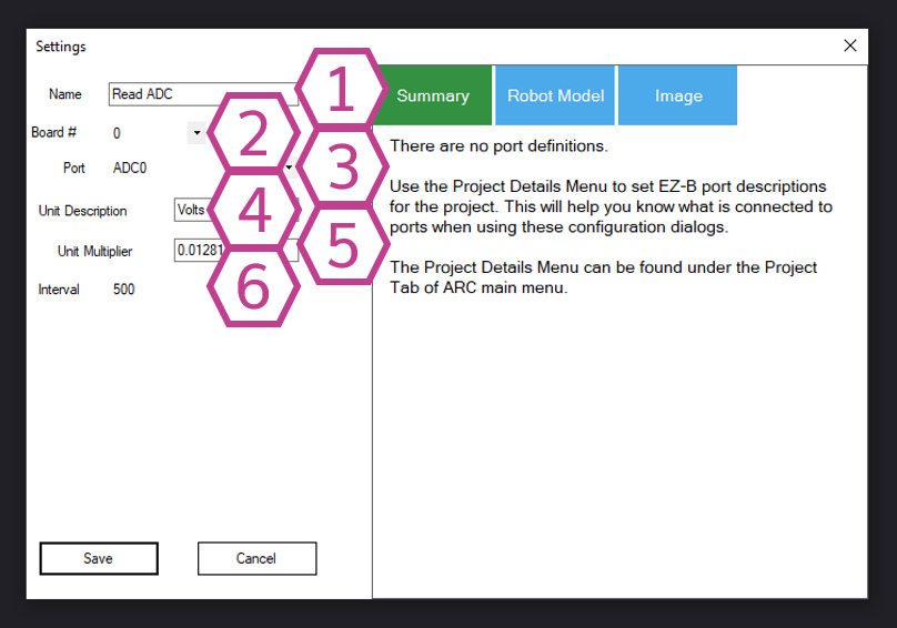
1. Title Field
The name of the Read ADC skill as it appears in your ARC project.
Note: Changing the title will also change the identifier used by
controlCommand() to reference this skill.
2. Board Drop-down
Select the EZ-B connection index (board number) that contains the ADC port you want to read.
This allows multiple EZ-B controllers to be used in the same project.
3. Port Drop-down
Select the ADC (analog) port that your sensor is connected to. Only ports that support analog
input will return valid readings.
4. Unit Description Field
Enter a custom unit of measurement to label the calculated value (for example: cm, °C,
psi, or lux). This is useful when converting voltage into real-world units.
5. Multiplier Field
Enter a multiplier used to convert the raw 0–255 ADC value into your chosen unit of measurement.
This allows scaling the ADC value to match sensor specifications.
6. Interval Drop-down
Select the delay (in milliseconds) between ADC samples. Shorter intervals provide faster updates
but increase processing and communication load. Longer intervals are suitable for slow-changing signals.
How to Use Read ADC
- Add the Read ADC skill to your ARC project: Project → Add Skill → ADC → Read ADC.
- Open Settings and select the correct Board and ADC Port where your analog device is connected.
- View the live numeric voltage and linear value in the Main Window. Use Pause to freeze the display if needed.
ADC ports measure voltage. Ensure your sensor output stays within the safe range of 0V to TTL High (3.3V or 5V). Exceeding this range may cause inaccurate readings or damage the controller.
Video
Requirements
Related Tutorials
Flex Sensor With An ADC Port Tutorial
Using ADC (Analog To Digital) Ports, Commands And Controls.
Related Hack Events

Related Questions
Hbridge And 10K Precision Pot For Feedback
Moving Head Sound Detector

Upgrade to ARC Pro
Experience the transformation – subscribe to Synthiam ARC Pro and watch your robot evolve into a marvel of innovation and intelligence.