Ellis
USA
Asked
Moving Head Sound Detector
How do I get my sound detectors to give constant voltage readings on the ADC Graph? I am using the two detectors to see where the loudest signal came from then move the robot's head toward the loudest.
I have read all I can find on Synthiam including the Community and Tutorials but can not see anything that will solve my problem.
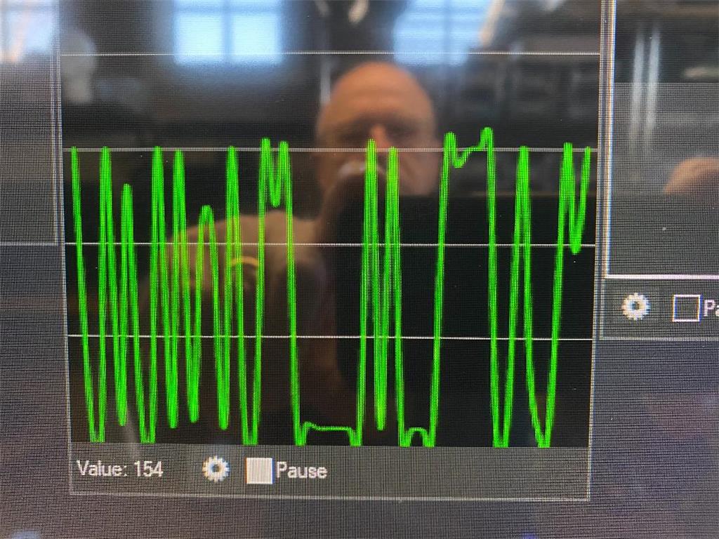
The problem is I can't get a consistent signal from in the ADC Graph. The line graph will jump up and down even with the a constant audio signal coming from my sound generator. Since their is no sound consistency I can't write script to make the head move.
Is my problem having to do with the wrong sound detectors or the way the information is handled by the Ez-Robot program?
Related Hardware (view all EZB hardware)
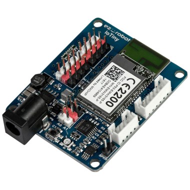
EZ-B Iotiny
by EZ-Robot
Control IoTiny with Synthiam ARC: 100MHz Cortex‑M4 Wi‑Fi IoT/robot controller-camera, servos, ADC, I2C and digital I/O for easy internet automation
Wi-Fi / USB
Servos
8
Camera
Audio
UART
✕
I2C
ADC
✕
Digital
✕
Related Robot Skills (view all robot skills)

ADC Graph
by Synthiam
Historical ADC graph and numeric readout (0-255) for 0-3.3/5V inputs; configurable board/port, sample interval, color, and pause for ezb controllers.

ADC Value
by Synthiam
Display ADC port voltage and 0-255 linear values (0-3.3/5V); configurable board/port, units, multiplier and sample interval.

ADC Meter
by Synthiam
ADC VU meter displaying 0-3.3/5V as a 0-255 linear meter; configurable board/port, sampling interval and color; pausable real-time readings.

Do your sensors require a pull-up or pull-down?
The sensors have both analog and digital. I am using analog pin. As I understand , analog provides a constant streaming variable voltage output.
Is there a gain on the audio sensor? Perhaps the gain is super high and picking up distortion? ADC will display what ever voltage it samples - garbage in is garbage out
The above pictures are Top ADC Graph, Next Sound Generator pictures.
Yes there is a gain control on both brands of sound sensors. I have tried from low to high on both of them to no avail. I added a 1000 ohm resister between signal and ground as per the tutorial instructions when I first built the system. I am beginning to wonder if this pull down resistor is only used when you are using the digital pin which I don't. I am going to try removing it and see if that changes things.
It is showing a signal when my Lab dog barks and sometimes when I make a loud voice sound at a higher pitch. It seems to prefer the higher frequencies. When I turn on my sound generator and run it at 5000 Hz the generator puts out a perfect sign signal tone. But on my ADC graph it shows a variable up and down signal. Again I want to have all three sound sensors in sync so I can write script to to calculate which is louder. I would like it to act like my Amazon Echo which with led's show where the sound is coming from. If I could use an Echo far field microphone setup I would. Right now I am trying to build my own.
Thanks PTP. Coding firmware is way beyond my skill level. I would love to use one of the arrays but do not know how to interface them with ARC so I can control a head rotate servo. Do you know anyone that has used a microphone array with ARC in this kind of situation.
I have seen someone on the Community make a robot answer which ear is hearing the loudest voice with sound sensors and it seems to work. I realize that that may not be exactly the same but if it can decide which ear is hearing it should be able to tell a servo to move in the direction of the loudest sound sensor.
Ptp, he’s merely trying to identify the direction of a sound. It should be straight forward with that sensor and adc though.
im wondering if a filtering cap would be useful. I have a sound sensor at the office. I’ll take a look at it this week and see if I can lend some advice
I believe others who determined the direction of sound may have used the sound movement control: https://synthiam.com/Products/Controls/Scripting/Sound-Movement-16110
Thanks DJ. I also think i can do it with sound sensors. I think I can write the code once I get the voltages outputs from the three sound servo's. I am using a Lol Tiny for testing since it has only two ADC0 and ADC1. I will use the EZ-B microprocessor for the three sound servo's.