
Asked
Hbridge And 10K Precision Pot For Feedback
I want to use a precision 10k pot for positioning feedback for hbridge control.
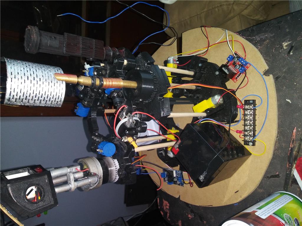
For my R2 I'm adding lifts for the periscope, radar and zapper but im unsure how to wire it for the ADC.
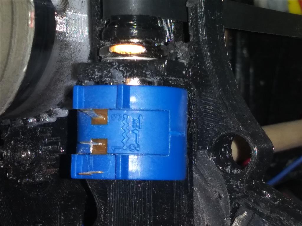
Im using a bourns pot, i understand pin 2 goes to the white pin of my adc port, for the reading, where do i get the power from for pin 1? I have 5 volts running the exb because that's the max my micro servos can take and i have 12v running into the hbridge for motor power.
Ive been looking through a lot of posts, and cant find reference to this, just not to get the power from the adc port.
This is a second ezb4 that will only be controlling 4 dc motors for lift, 4 micro servos for spinning the stuff, an led for the zapper and a 3v air pump for smoke.
Related Hardware (view all EZB hardware)

EZ-B V4
by EZ-Robot
EZ-B v4/2 robot controller: dual Cortex ARM, Wi-Fi, audio/video, 24 servo/digital ports, I2C/UART, camera and Synthiam ARC control for custom robots
Wi-Fi / USB
Servos
24
Camera
Audio
UART
3
I2C
ADC
8
Digital
24
Related Robot Skill (view all robot skills)

ADC Value
by Synthiam
Display ADC port voltage and 0-255 linear values (0-3.3/5V); configurable board/port, units, multiplier and sample interval.

POT: PIN 1 = EZB adc's port black pin = GND PIN 2 = EZB adc's port white pin = input PIN 3 = EZB adc's port red pin = 3.3v
Use the electronics (pcb) of servo and connect it to an hbridge. It’s way easier and gives you fine control of positioning.
Dj sures, i have a couple questions. I've been reading through the forums and can't find details on how the pcb board is connected to the hbridge, is there a post or tutorial i should read on the hook up?
This question might be answered by said post. Once hooked up are the controls a servo or scripts? Auto Position would sure be nice if its connected as a servo.
I have an Amazon gift card burning a hole in my pocket, is any digital servo good to use?
Thanks
Try something like this:
The h-bridge requires 5v logic, so the servo PCB must be fed with 5v. If your EZ-B is connected to a 5v power source you can connect the servo pcb directly to EZB digital port (vin/red), if not you will need a DC/DC to get the 5V from the vin.
If your motor is spinning in the opposite direction you ll need to swap the connections between the servo and h-bridge e.g. OUT1 -> IN2 / OUT2 -> IN1
Nice drawing ptp! You got it dead on!
That is great! I sure hope others will see and use your drawing too.
I'll be sure to post once i get it set up.
Nice!! People will appreciate a demo. I’ve been saying to use hbridge with servo pcb’s for years but don’t think anyone has. It’s essentially a super powerful but cheap saber tooth. I kind of invented it on my own cause I’m a little crazy like that ... but it’d be neat to see more people adapt it