


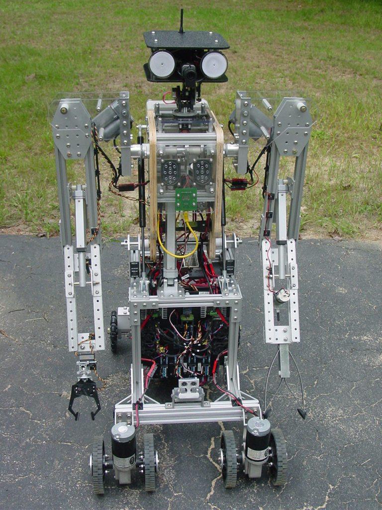


For the last decade or more I've been working on a series of large robots with articulated arms. I just finished the latest version, ARMadeus Mk7. Considered mid-size compared to some of its descendents, it measures 48" tall and weighs 112 pounds. Some of the main components include:
(3) 12V DC gear motors (4) Servos (6) 12V linear actuators (4) IFI Victor 12V speed controllers (2) Sabertooth 2x12 speed controllers (2) IFI Spike H-Bridge relay modules (1) Audio player (1) video camera w/ 2.4GHz transmitter
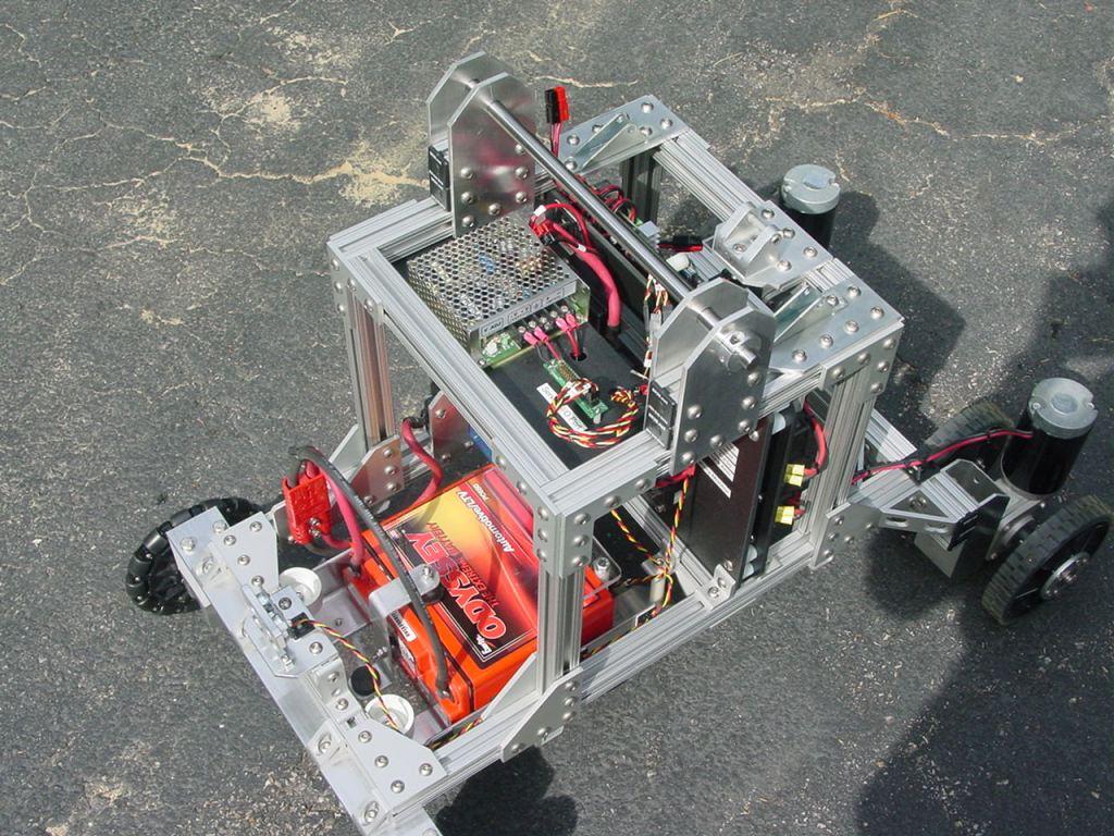
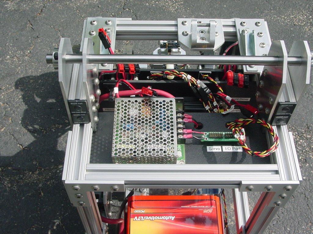
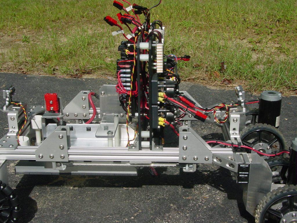
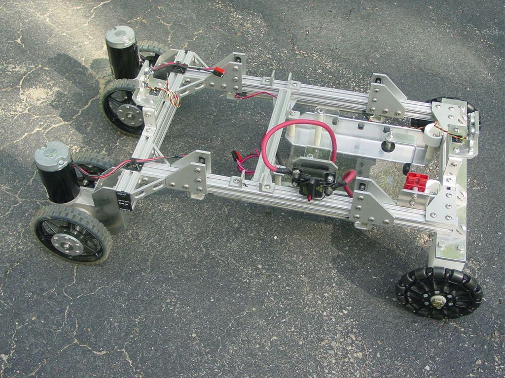
There are two common features that I consider essential when designing large-scale robots, adjustability and modularity. All of the ARMadeus robots have been built using 80/20 aluminum t-slotted extrusions and joining plates. It allows for flexibility in repositioning parts without having to drill holes. The first picture shows the lower 21" wide x 32" long lower chassis and drive train.
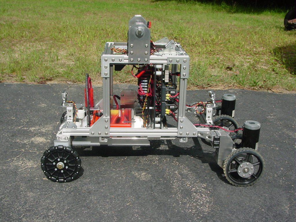
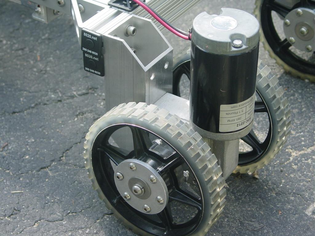
Here's a closeup of one of the drive units, consisting of an NPC 2212 12V 285 rpm gear motor and 2 AndyMark 6" HiGrip wheels.
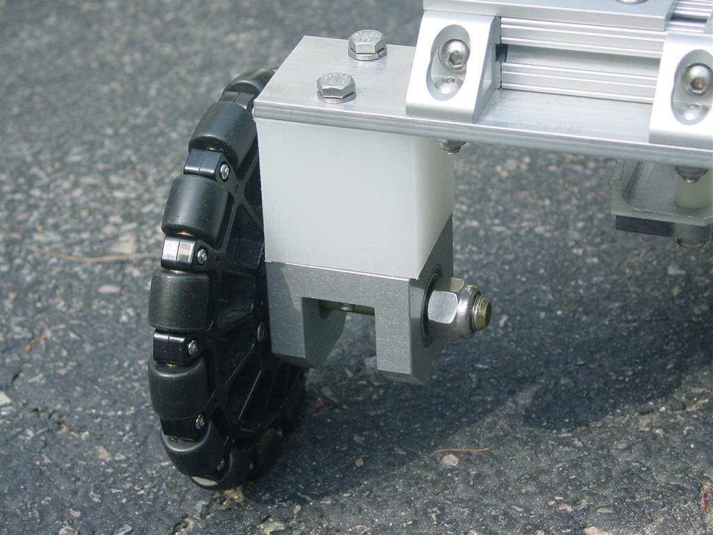
The rear wheel assembly uses an AndyMark 6" Omni wheel.
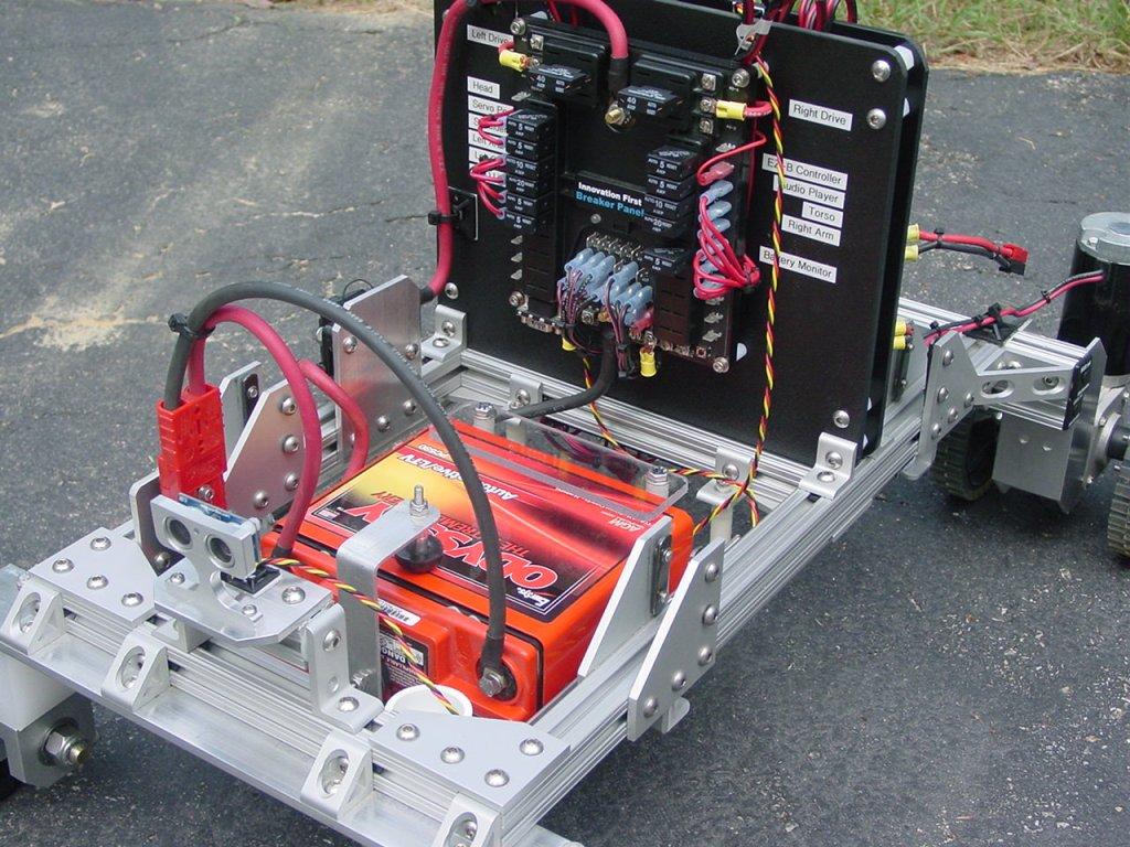
On one side of the chassis is the main power switch/120 Amp circuit breaker. A blue LED light tube for effect lighting can be seen just under the chassis rail.
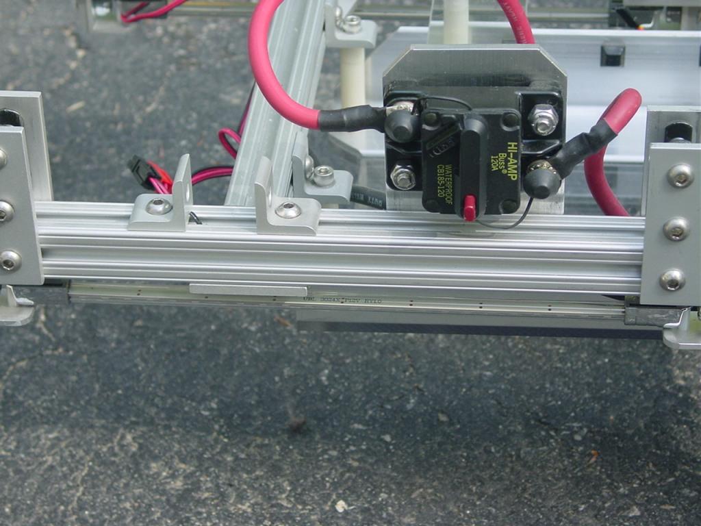
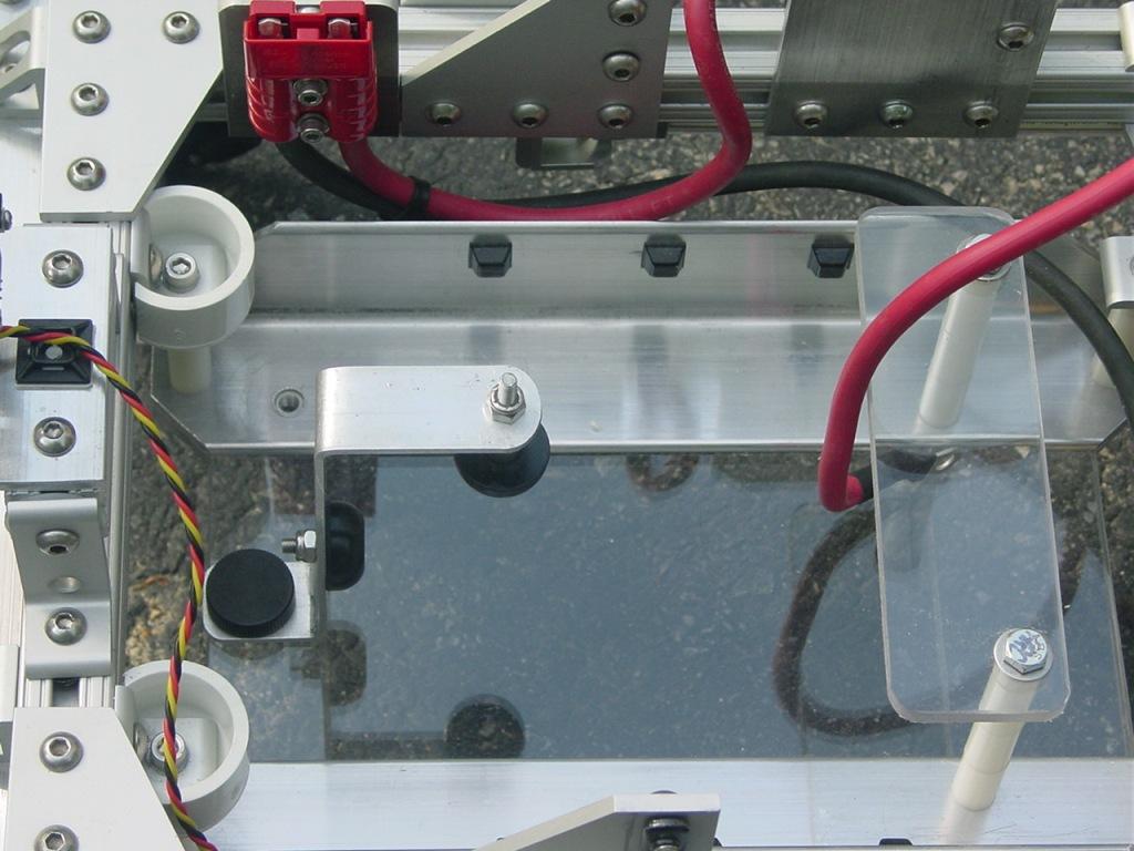
The robot is powered by 12V 17AH Sealed Lead Acid battery. The 15 lb battery is mounted horizontally on a tray near the back of the robot and acts a counterweight when the robot arms and torso are fully extended.
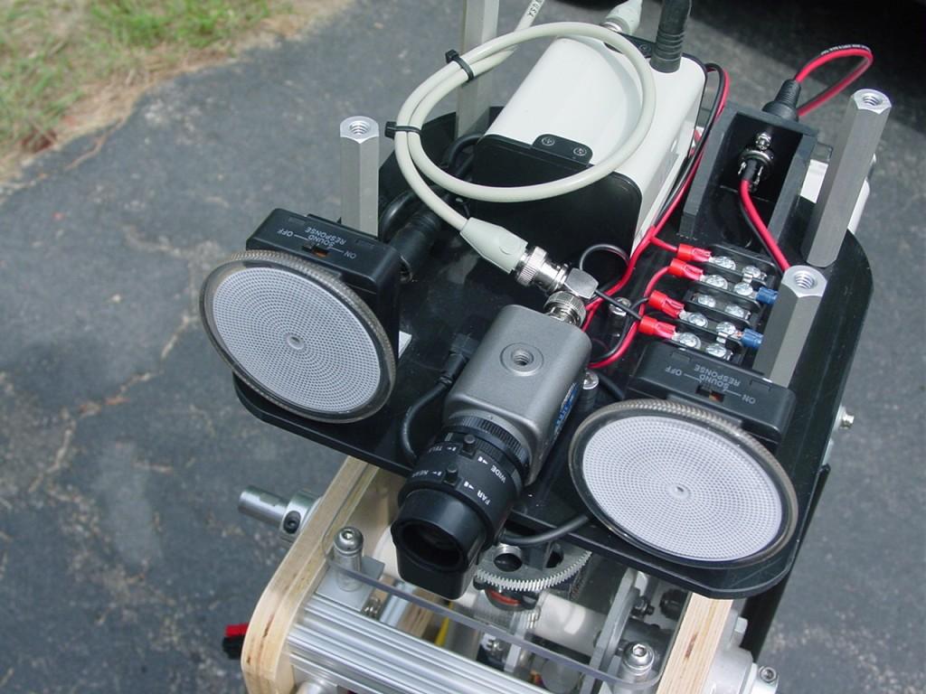
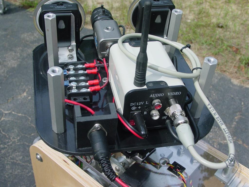
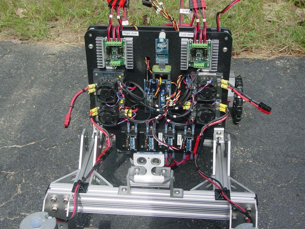
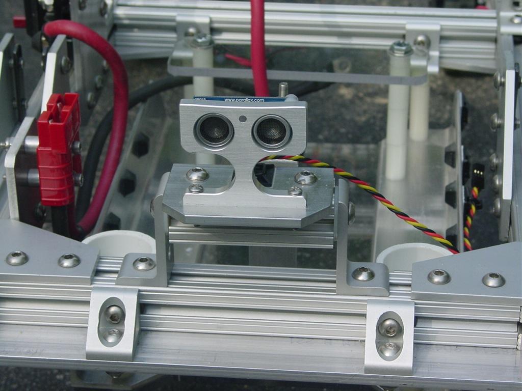
Front and rear Parallax PING sensors are mounted on tilting brackets as shown below.
I will post pictures of the remaining subsystems and the completed robot during the next few days.
Discover more robots
Cardboardhacker's Technopro's Live Wall-E Build (Saturday,...

DJ's Cyborg Snowman


WOW
Very impressive Jim! Great work. Do I count 6 motor controllers? I'm still saving for just 1 Sabertooth 2x25 ... lol Being retired has some advantages (more time for robots) and disadvantages (a lot less funds).
Question: It looks to me the front wheels are stationary. How does it turn?
Really looking forward to seeing this one in a video.
Herr
Herr,
Yes, 6 physical motor controllers. The sabertooths are dual for a total of 8 individual controllers. There are 2 drive motors and 6 linear actuators that need motor speed control. One smaller motor for the left hand gripper is controlled by a relay. 4 servos handle the rest of the movement functions.
The robot uses front wheel drive. The two front drive motors have a common keyed shaft that comes out both sides of the motor's gearbox. A pair of wheels are mounted on keyed hubs that mate with the shafts. Driving the two drive motors in opposite directions along with the unpowered rear omni wheels allow the robot to turn easily.
I don't.understand how this guy.turns
Both wheels on the drive unit turn together because they are on the same shaft that runs through the right angle transmission. I could have easily just removed the two inner wheels, one from each motor. I didn't want to cut the half of the shaft off, so I left it intact. The inner wheel provides a little extra traction and equalizes the load on the output shaft. Turning is no different than a smaller bot using continuous rotation servos with wheels mounted at the front. The rear omni wheels simply act like casters allowing the back end swing around as the robot turns. This wheel arrangement allows the robot to make tight turns in the front, pivoting at a point halfway between the two drive units.
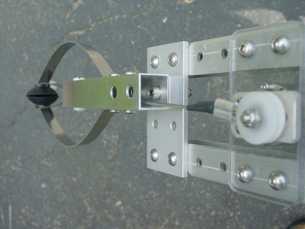
Meanwhile, back at the ranch. The plan was always to make both arms identical in construction but, use different style grippers. The left hand gripper was used successfully before on other ARMadeus models, thus becoming a viable organ donor. The basic gripper mechanism was hacked from an extended reach gripper available at many hardware stores for $10 or less. I saved the steel springs and rubber cups and mounted them in a larger 1" square aluminum tube. The first picture shows the hacked gripper before I shortened the mounting tube for the Mk7.
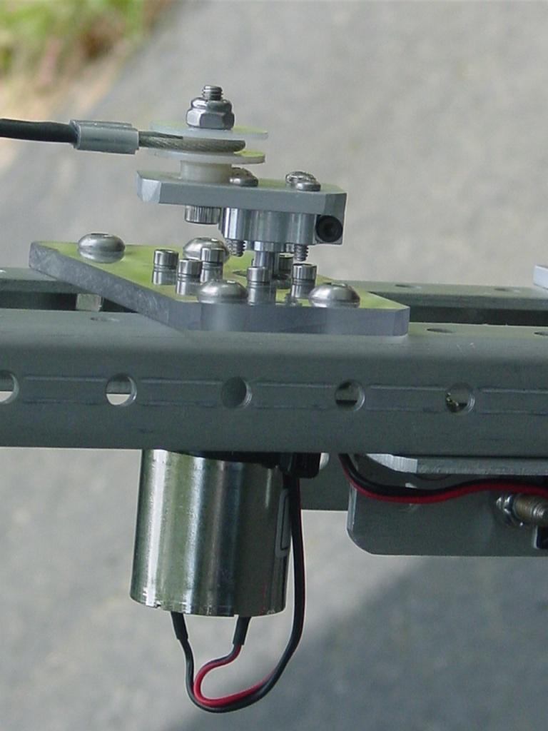
The gripper is actuated by pulling on the cable causing the spring fingers to contract. I used a ServoCity 12V 10 rpm motor with a crank mechanism attached to the motor shaft. The motor rotation is translated into linear motion. The fingers open and close in sync with the rotation of the motor. The rubber cups and spring fingers make this a highly compliant gripper. The following two photos show a closeup of the motor and crank and, the gripper fingers in the closed position. One of the Spike H-bridge relays controls the direction of the gripper motor.
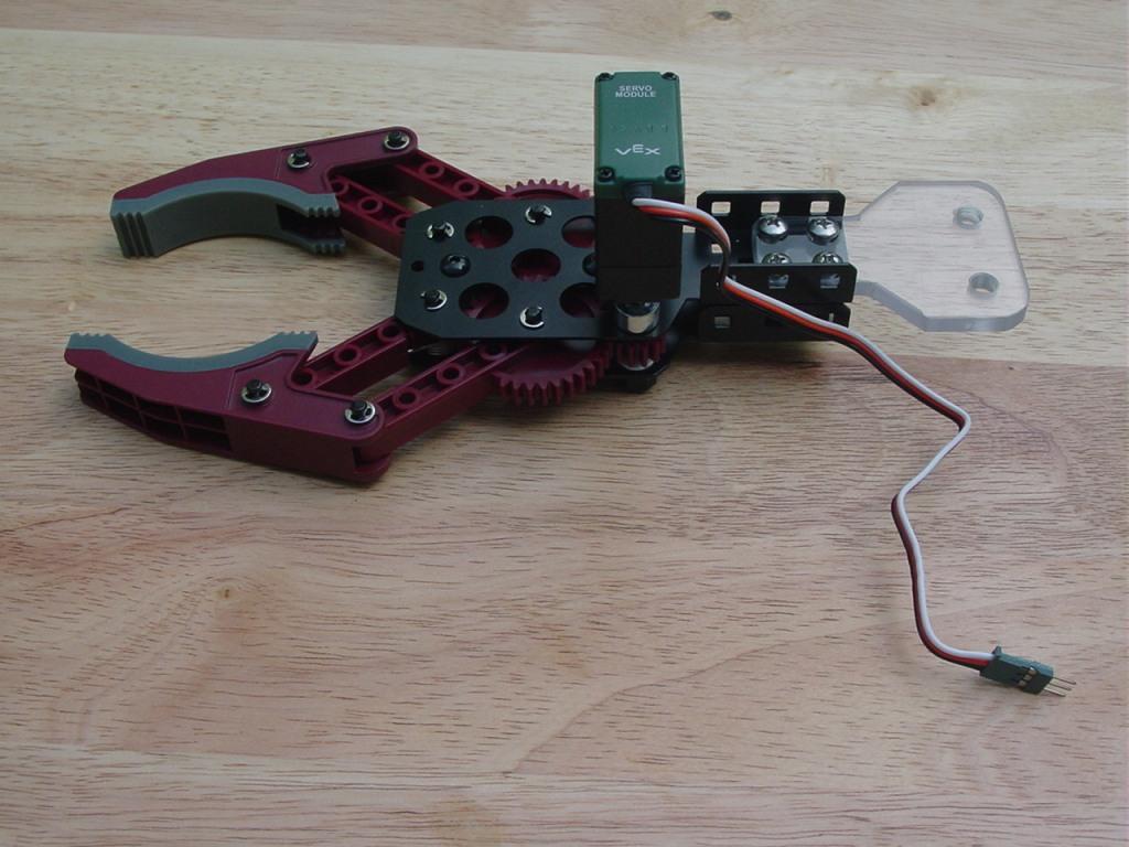
I debated about which gripper to put on the right hand. My original thought was to build a universal jamming gripper, the type that uses a vacuum pump and a balloon filled with ground coffee. I will save that idea for another day. The next thought was to use a VEX claw and servo. All I had to do was fabricate a simple polycarbonate plate for attaching the claw to the end of the forearm. Since I already had one in my collection, I would try it. It is pictured below.
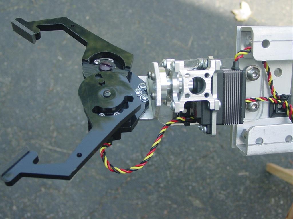
In the end I decided on a gripper that also had a rotatating wrist. A ServoCity servo block and a Hitec HS-7955TG servo provides 180 degrees of wrist motion. A Robodyssey gripper with a Hitec HS-985MG servo completes the assembly.
The next installment will detail the arm construction and a collection of photos of the completed robot.
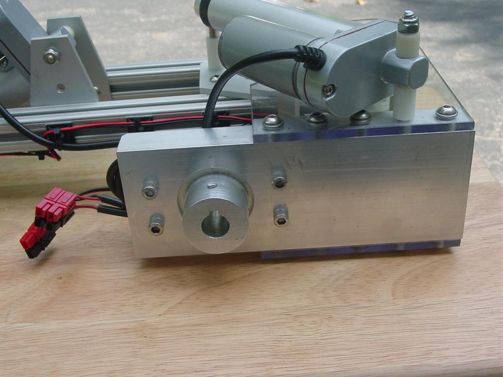
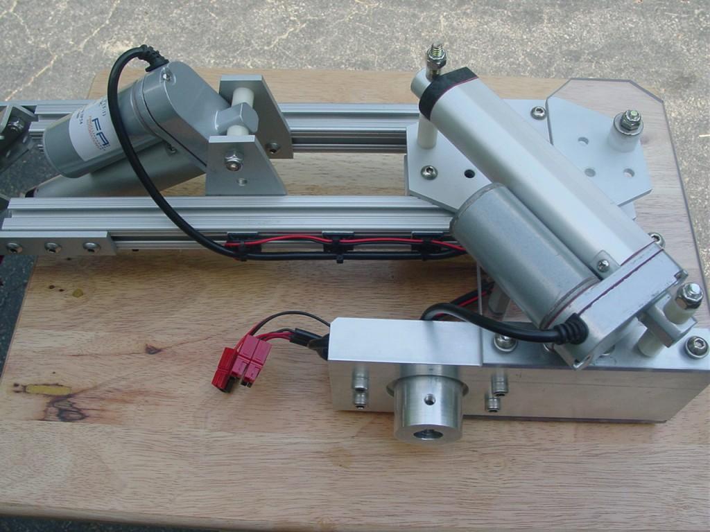
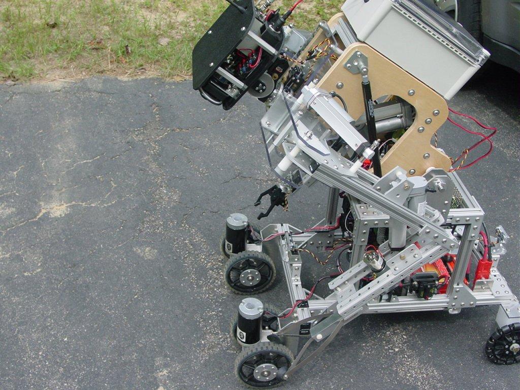
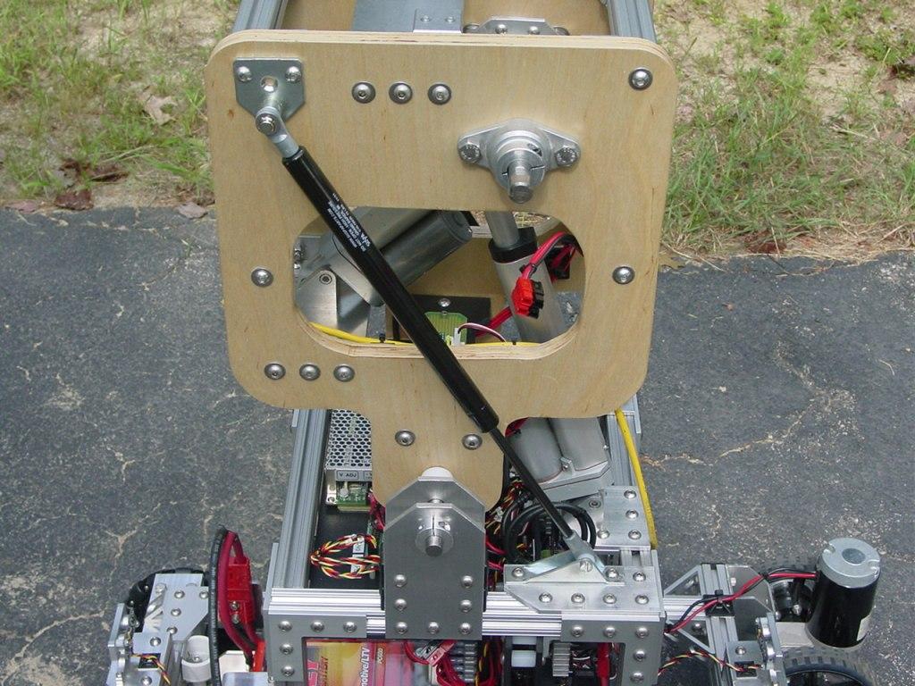
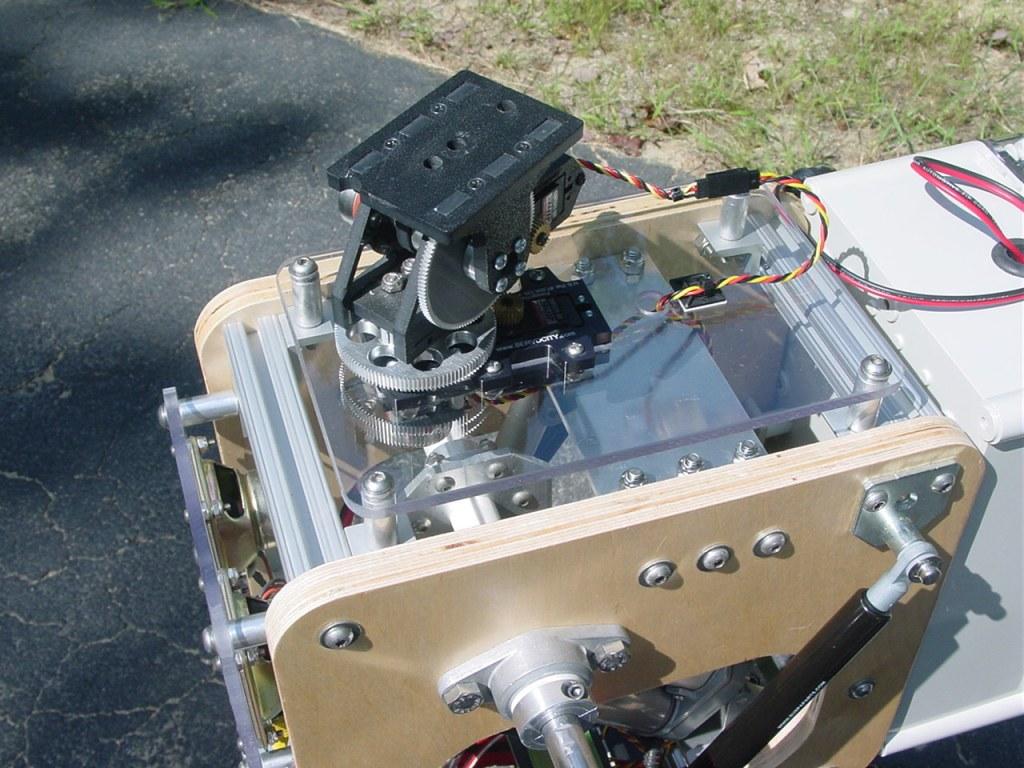
Here is the final installment of the ARMadeus Mk7 build report. Each arm weighs 11 pounds. Both arms are connected to a common shoulder. A linear actuator inside the torso rotates the 5/8" diameter shoulder shaft 90 degrees. A keyed aluminum hub connects the arm to the shaft. Each arm uses two independent 3" stroke linear actuators, one to swing the upper arm outwards and another to extend and retract the forearm. To gain some mechanical advantage when raising the arms, much of the upper arm assembly was located one side of the axis of shoulder rotation with the forearm on the other side. This counter balance greatly reduces the load on the shoulder rotation actuator.
The next two photos illustrate the arm hub and upper arm assembly.
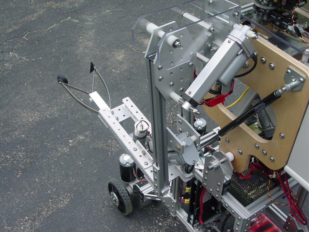
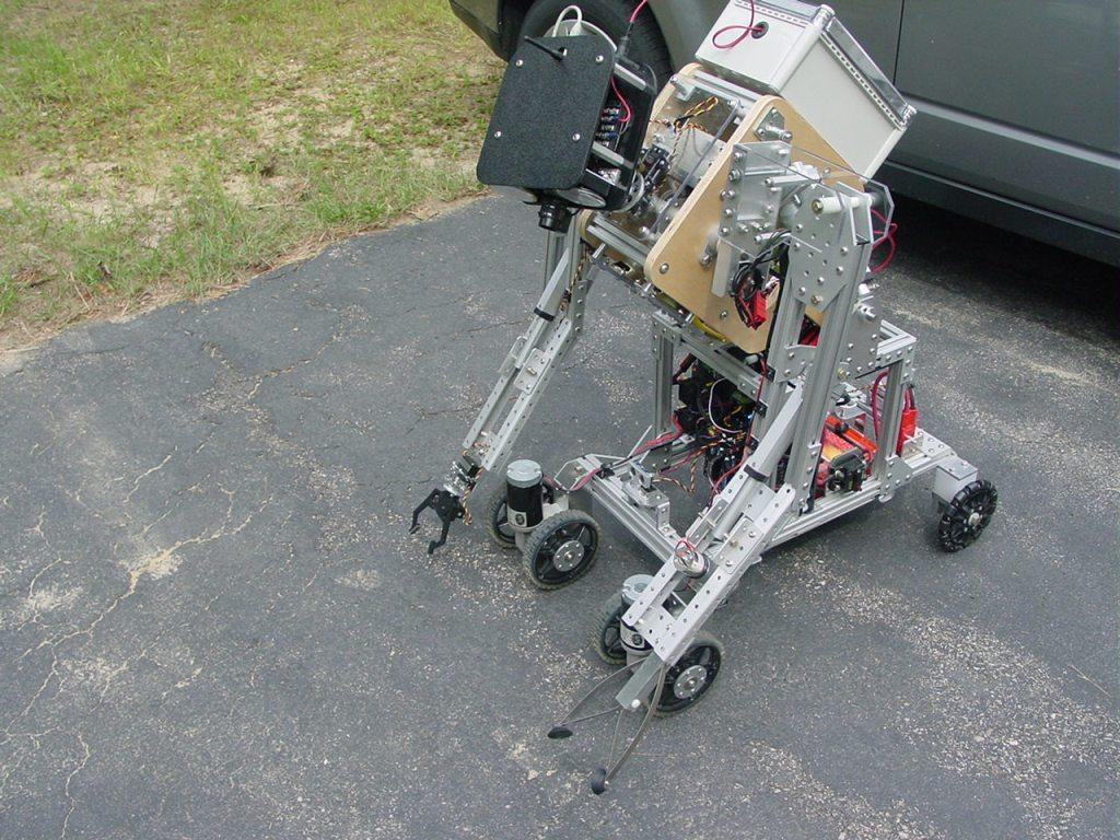
Next is a picture of the complete left arm and compliant spring gripper.
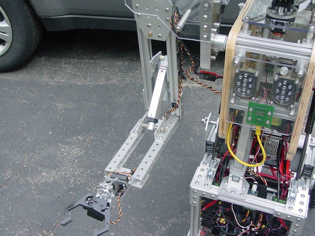
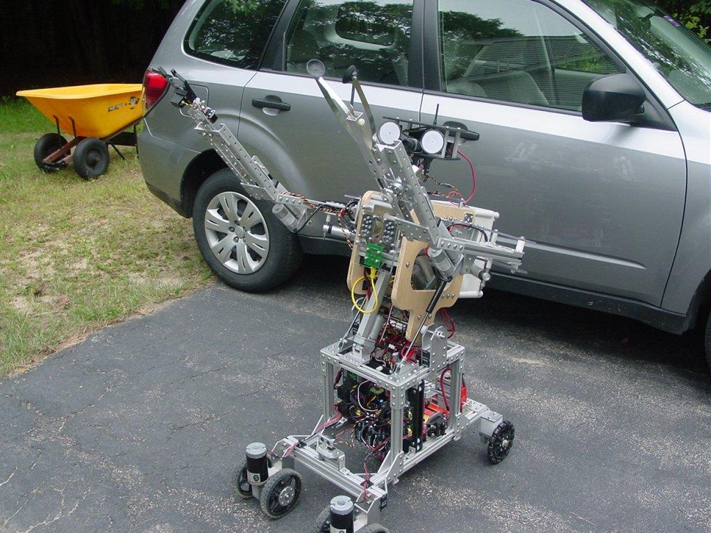
Here are two views of the complete right arm and servo gripper.
Several builders have asked for a video of the robot. I don't have one yet and it may be awhile. For the time being I offer a series of still pictures showing the range of torso and arm motion of the completed robot.
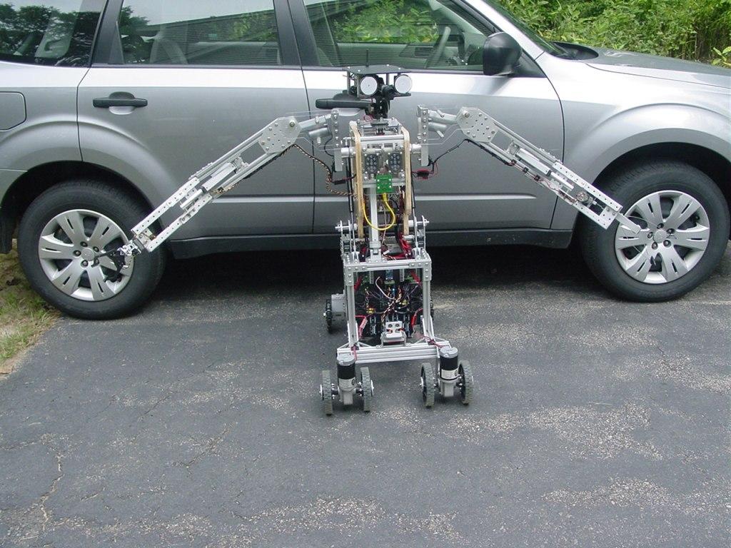
Here are front and rear views of ARMadeus Mk7 at rest.
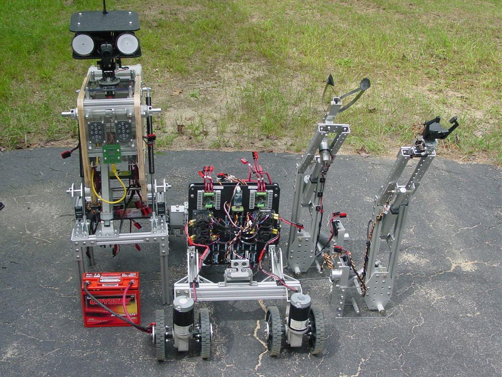
Finally, here is a picture of the robot disassembled for transport. Thanks to the modular design, it takes me about 3 minutes to break the completed robot down to these 5 components and only slightly longer to reassemble it.
Well that's it for now. Will there be a Mk8? Indubitably. I suspect the redesign may not be as drastic as some of the others have been. Now that school has started, much of my spare time will be directed to supporting a local FIRST robotics team as an engineering mentor. Any future personal robot projects will have to wait until next spring.
Thanks very much for showing the steps you performed in this thread, it certainly opens the engineering mind to more creativity in this realm of robotics.
WOW!