

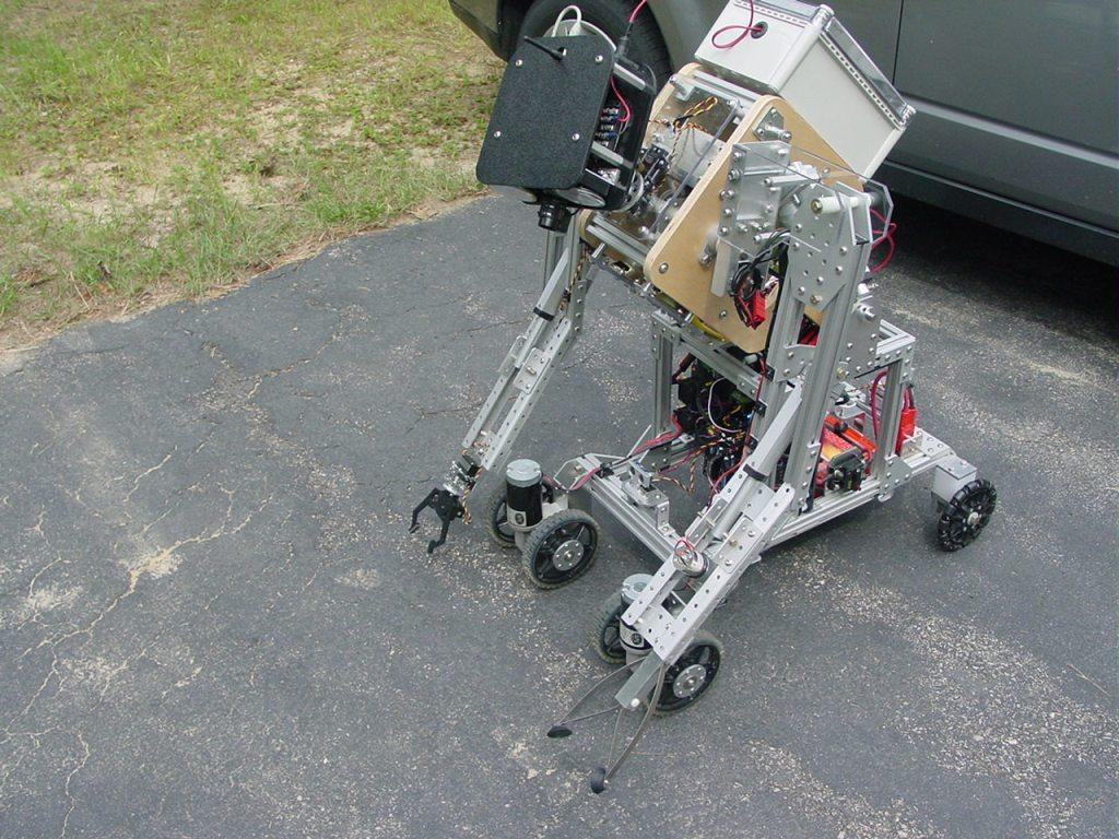

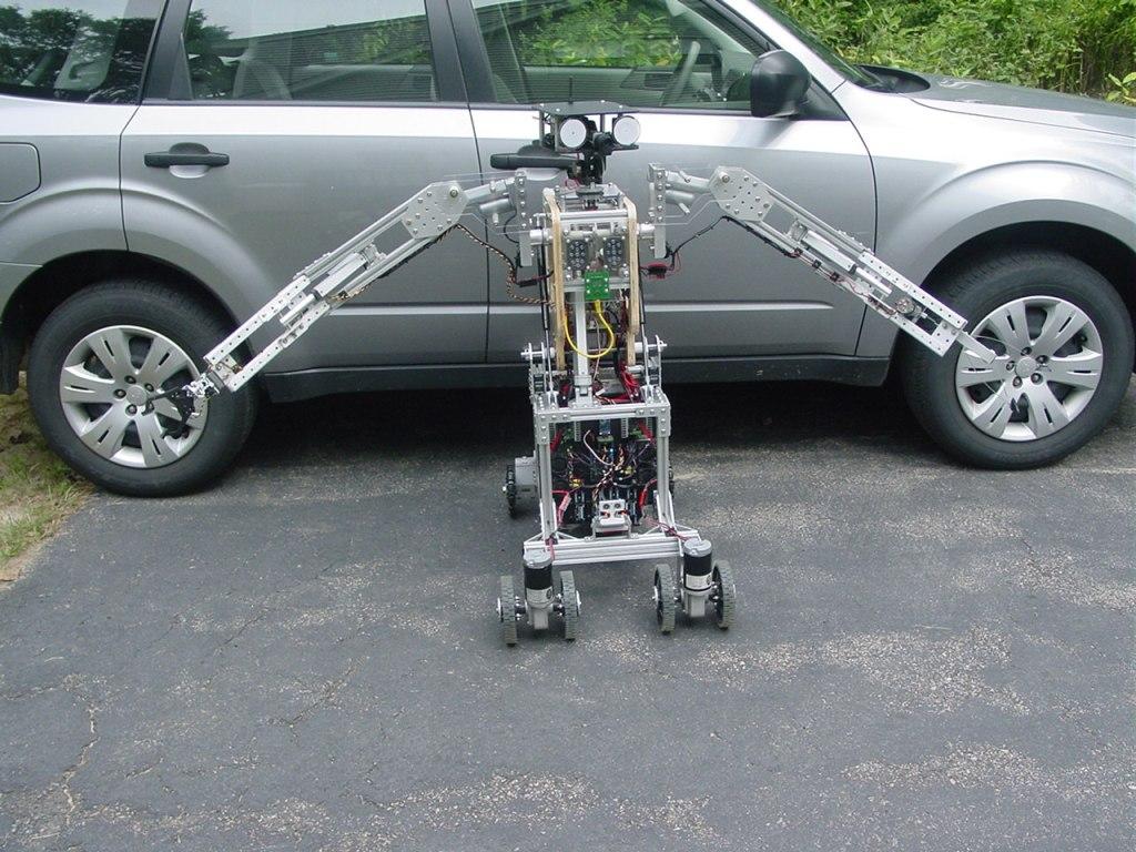
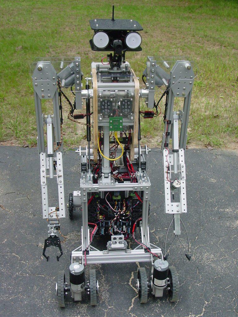


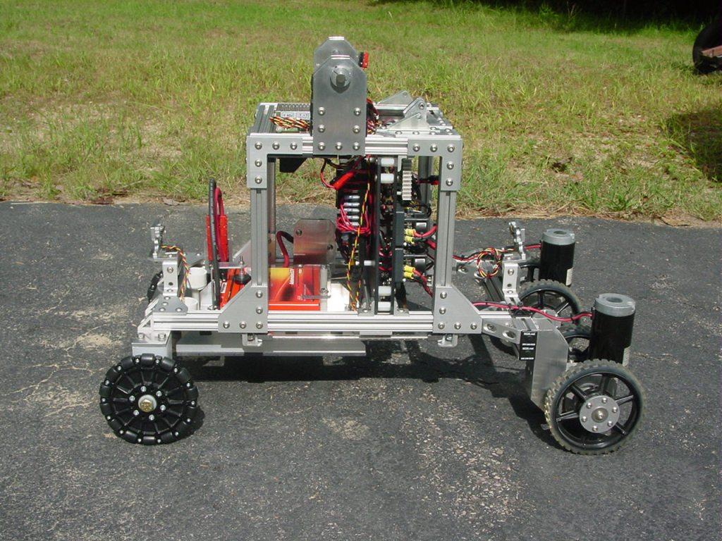
For the last decade or more I've been working on a series of large robots with articulated arms. I just finished the latest version, ARMadeus Mk7. Considered mid-size compared to some of its descendents, it measures 48" tall and weighs 112 pounds. Some of the main components include:
(3) 12V DC gear motors (4) Servos (6) 12V linear actuators (4) IFI Victor 12V speed controllers (2) Sabertooth 2x12 speed controllers (2) IFI Spike H-Bridge relay modules (1) Audio player (1) video camera w/ 2.4GHz transmitter
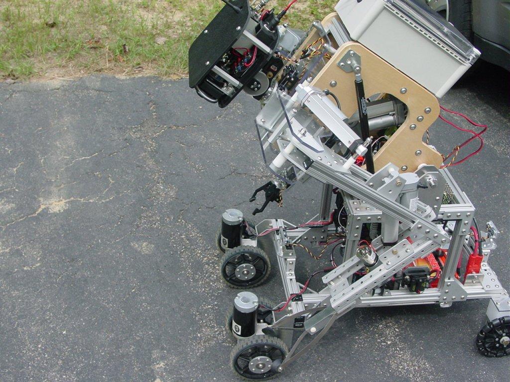
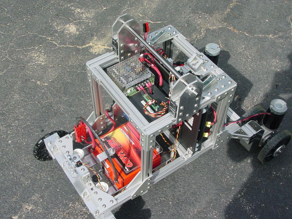
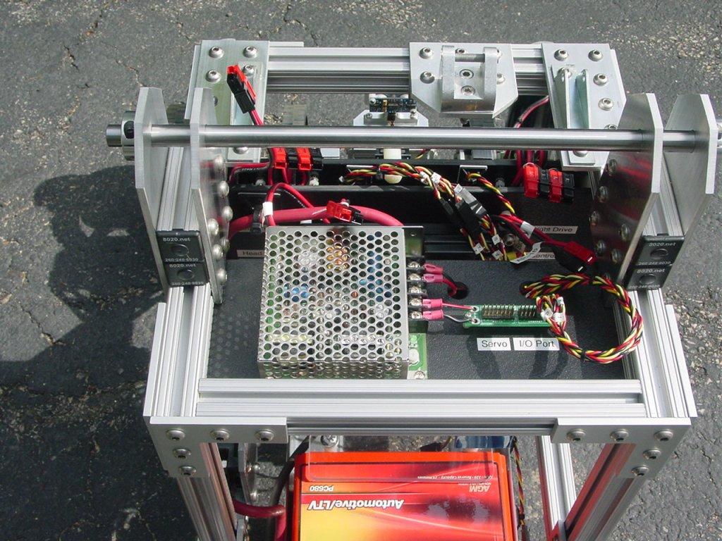
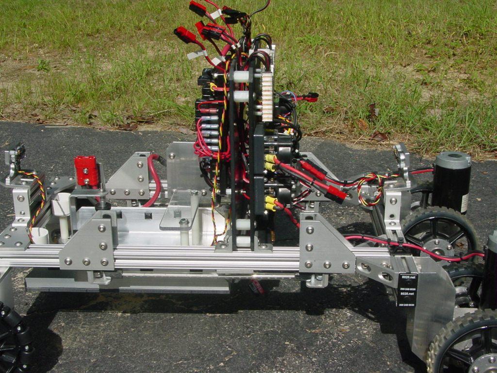
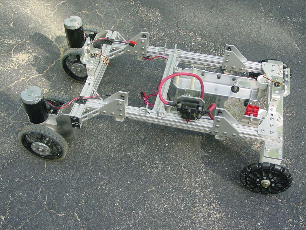
There are two common features that I consider essential when designing large-scale robots, adjustability and modularity. All of the ARMadeus robots have been built using 80/20 aluminum t-slotted extrusions and joining plates. It allows for flexibility in repositioning parts without having to drill holes. The first picture shows the lower 21" wide x 32" long lower chassis and drive train.
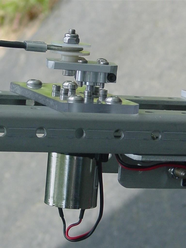
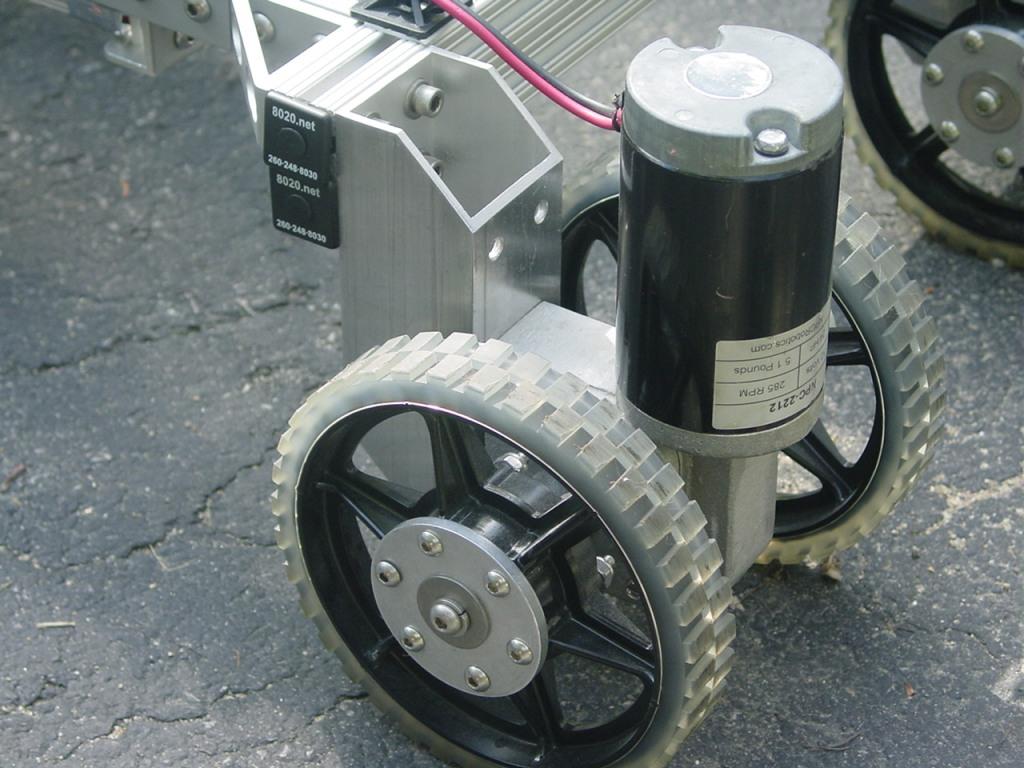
Here's a closeup of one of the drive units, consisting of an NPC 2212 12V 285 rpm gear motor and 2 AndyMark 6" HiGrip wheels.
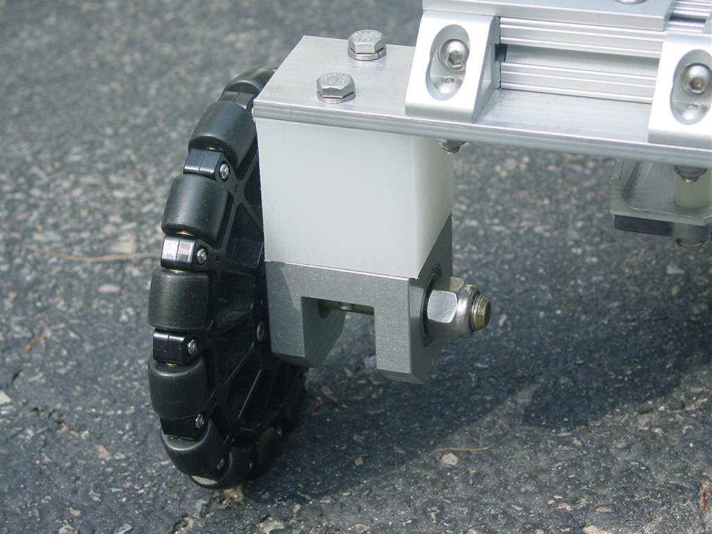
The rear wheel assembly uses an AndyMark 6" Omni wheel.
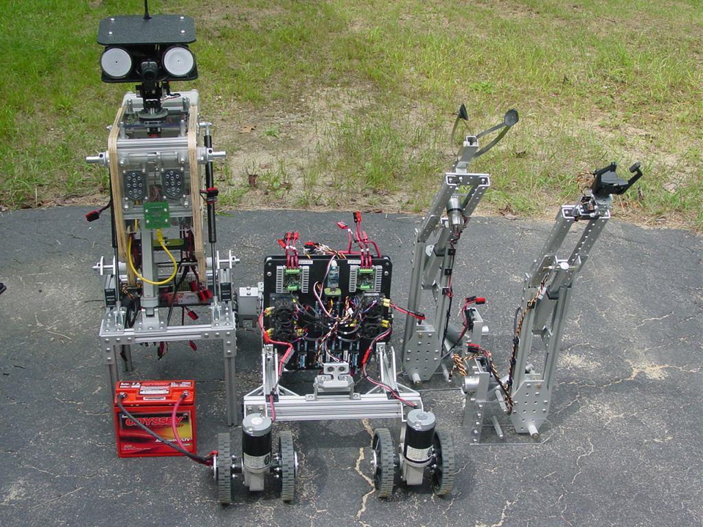
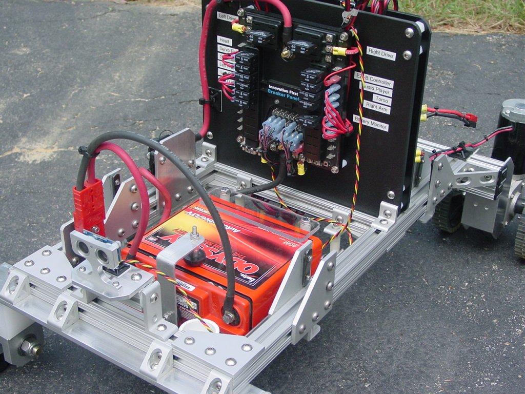
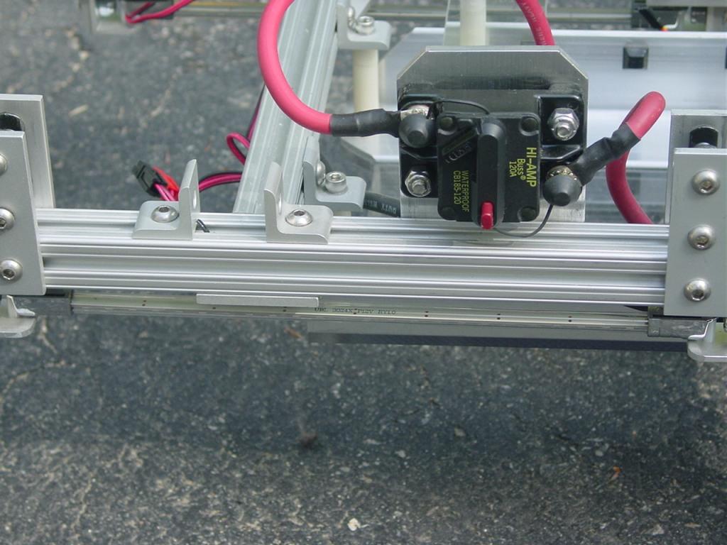
On one side of the chassis is the main power switch/120 Amp circuit breaker. A blue LED light tube for effect lighting can be seen just under the chassis rail.
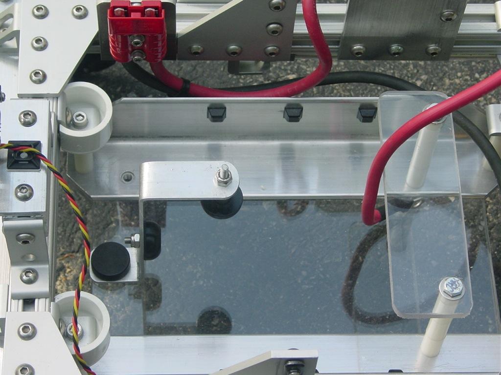
The robot is powered by 12V 17AH Sealed Lead Acid battery. The 15 lb battery is mounted horizontally on a tray near the back of the robot and acts a counterweight when the robot arms and torso are fully extended.
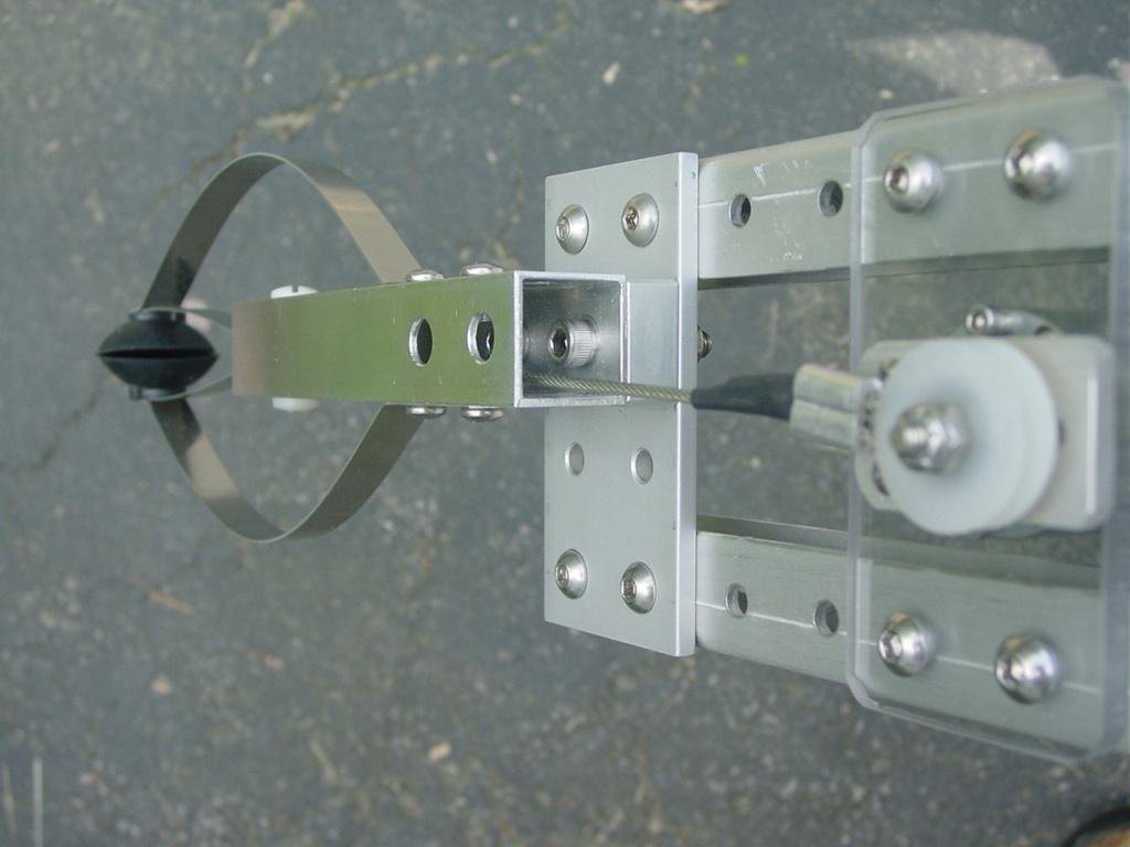
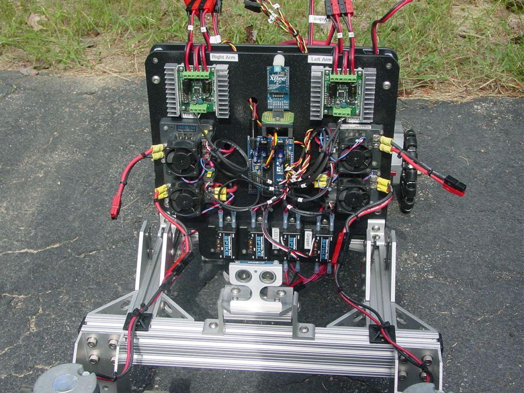
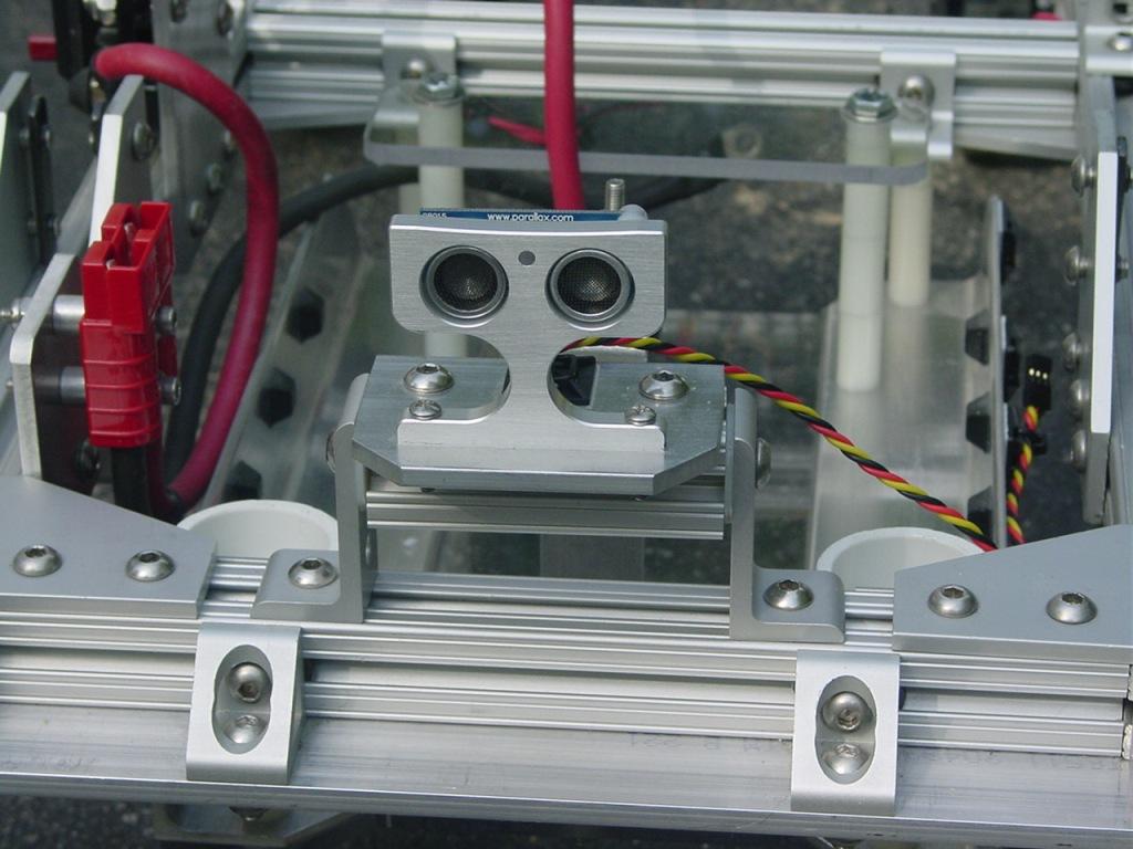
Front and rear Parallax PING sensors are mounted on tilting brackets as shown below.
I will post pictures of the remaining subsystems and the completed robot during the next few days.
Discover more robots
Jim's Armadeus Mk. 11

DJ's Teddy Ruxpin Robot V1

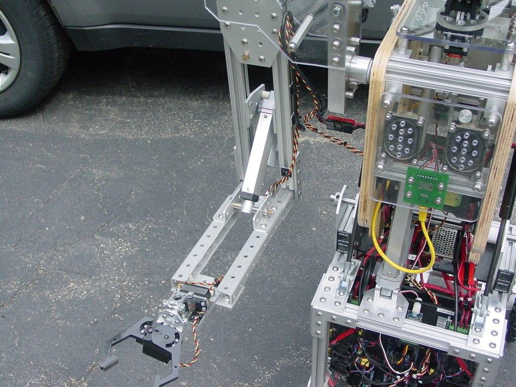
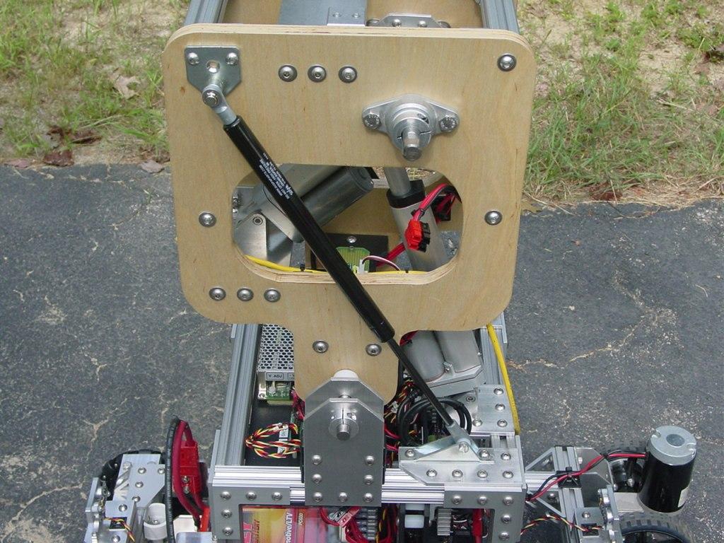
...And now for something completely different. As a departure from all the aluminum used so far in building the chassis, the torso was constructed from 3/4" birch plywood. Two 12" x 16" side panels were cut, shaped, and sanded. The two panels were taped together and drilled on a drill press, ensuring perfect hole alignment between the two sides. The ends of four 6" lengths of 80/20 extrusions were tapped with 1/4-20 threads and used as spacers. A center cutout in each side reduced the weight without sacrificing structural integrity and provided ready access to the interior. In keeping with the modular theme, right angle corner brackets were fastened to the spacers with threaded inserts crimped on the bracket's open side. This allowed attachments to be easily mounted to the front, rear and, top of the torso.
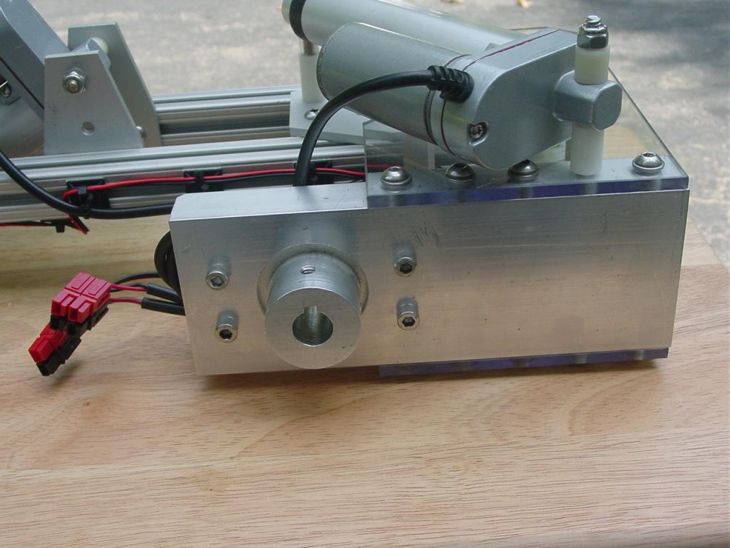
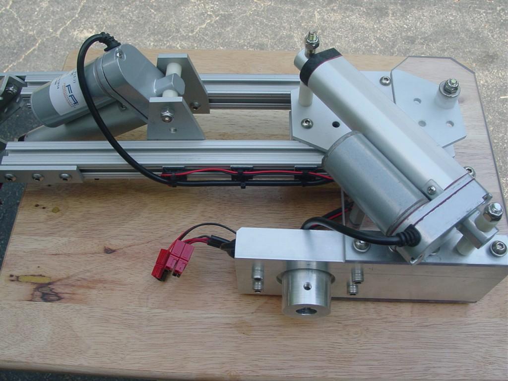
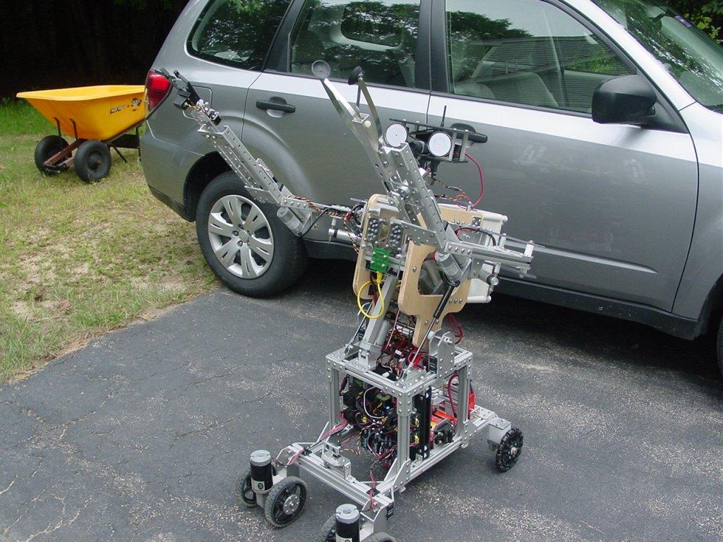
A 5/8" diameter fully-keyed steel shaft supported by aluminum flanged bronze bearings serves as the common shoulder joint for both arms. A 3" stroke linear actuator with over 100 pounds of force drives the shoulder through 90 degrees of rotation. A 6" stroke linear actuator mounted between the torso and upper chassis allows the entire torso to rotate from 10 degrees back to 45 degrees forward.
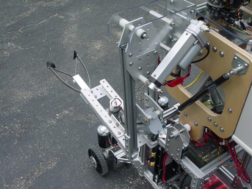
Some backlash in the torso's linear actuator and its mount caused the torso to move slightly when the torso was in the normal vertical position. I found this objectionable since a video camera was to be mounted on the head. The solution was simple and addressed two issues. I added a gas shock with 15 pounds of force to each side of the torso. The gas shocks absorbed the backlash and kept a constant force on the torso. The gas shocks also eased the burden on the linear actuator by providing additional lift when raising the torso from its full forward position.
A Dimension Engineering dual axis, 6G accelerometer was installed over the hip joint shaft and provides tilt position telemetry back to the PC through an ADC port on the EZ-B.
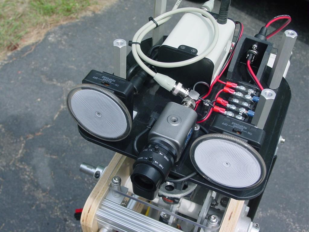
Initially, I mounted an EFX-TEK AP-16+ .wav file player to a polycarbonate (Lexan) plate on the back of the torso. I soon realized that the sound board would be dangerously exposed in this location. Besides, I generally don't mount sensitive electronics to polycarbonate, as it too readily holds static charges. As an alternative I installed the sound board on an ABS panel inside a covered project box. This backpack module also houses a 4 channel video mux slated for future use.
A speaker panel was added to the front of the torso. An interface board to the speakers also contains a 12dB audio attenuator, since the stereo amplifier on the sound card was rated at 20W/channel but the small speakers were only good for 5W.
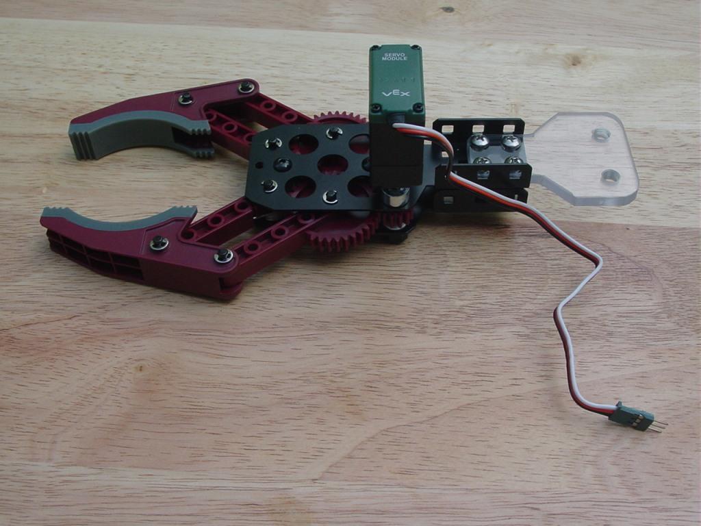
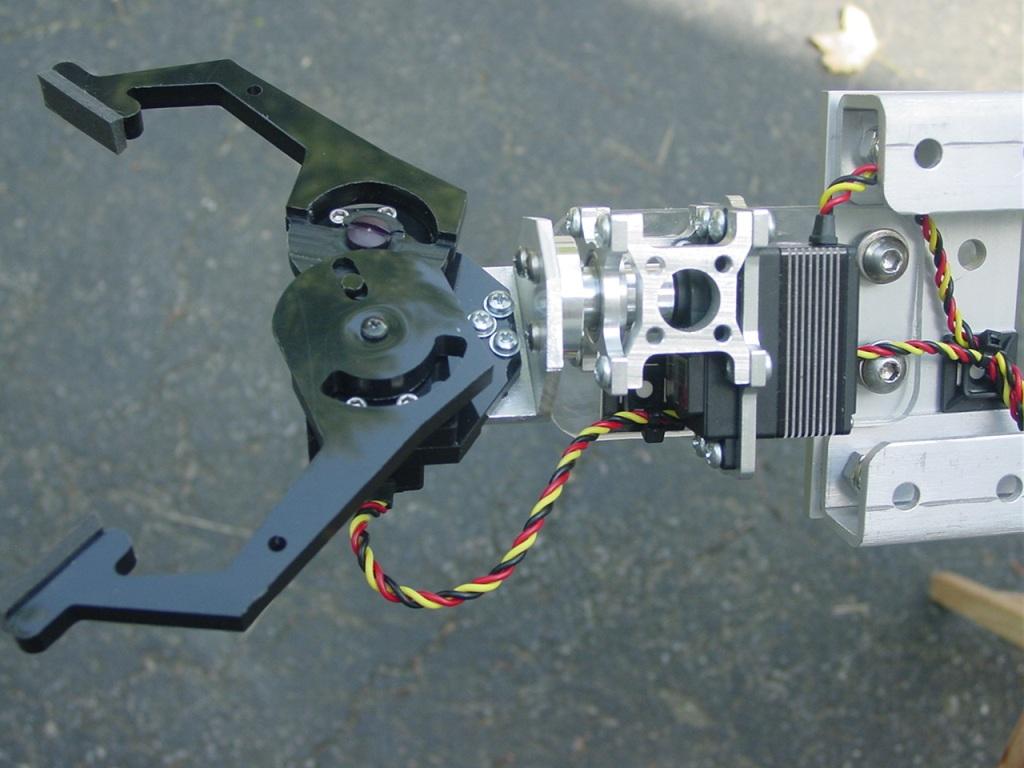
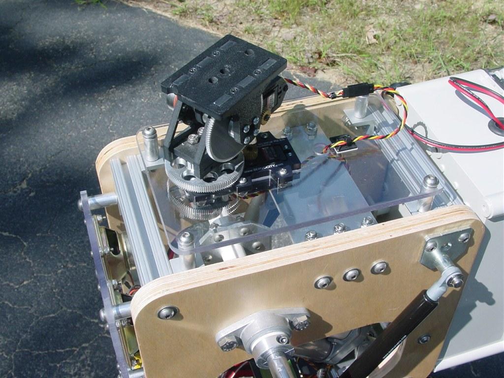
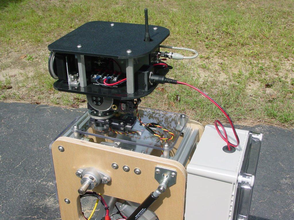
A ploycarbonate plate with servo City 5:1, pan and tilt units was added to the top of the torso. Both units use Hitec HS-645MG servos.
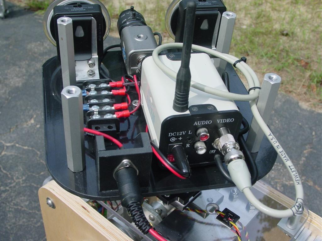
The next three photos are views of the head that mounts on top of the pan/tilt assembly. The head contains a color video camera with a 2.9-8mm auto-iris lens and a 2.4 Ghz video transmitter. During initial video tests, the video transmitter caused interference with the XBee communication. Setting the video transmitter to higher frequency channel fixed the problem. For no other purpose than to look cool, I installed two 3" diameter blue plasma disks in the head as eyes.
The final two installments will detail the grippers and arms, and pictures of the completed robot.
This is so cool!
Wow ,.that is a really big robot , is he small enough to navigate your.home?
Folks, thanks for all the favorable comments. I hope the pictures and text are providing the right level of detail to those following this thread. Considering the diverse audience, it's difficult to know where to draw the line. If anyone has any questions, feel free to ask.
With the arms down by its sides the robot is about 26" wide at the shoulders and easily navigates though a normal doorway. Obviously, I have to severely restrict its speed indoors. A 100+ pound robot rapidly accelerating (F=ma) can do a lot of damage in a very small period of time, as demonstrated by some unplanned modifications I made to a plastic shelving unit in my basement.
The Mk7 is actually one of the smallest members of the ARMadeus family. An earlier Mk3 model was nearly 6 feet tall, weighed 165 pounds and, was prone to face plants if its speed and direction changed suddenly. It was much less modular in nature and never spent much time outside of my basement. More than anything else these robots provide an opportunity to improve my design and construction skills, allow me to explore multiple areas of science and engineering and, create something truly unique. All of my robots have a very short lifespan. Almost as soon as the current version is completed, I start thinking about improvements and modification for the next one. Mmm...What could I do with a second EZ-B?
Lol , second ezb , twice as much as the first. My 3ft tall robot Jarvis is using two boards. All the sensors and motors control on the first and all the neck and arm servos on the second. This la my very first robot so I learn from.pictures and descriptions of them. My thread is like 185 pages of discussion and pics of mods and no one is complaining so take as many as possible =)
Jim Milan: your work is spectacular, feel free to add a video or many videos from your robot in motion, I'm sure that will be pleasing to all.
Oh yes , videos for sure. Show us how it works
Looks like it could survive a building collapsing on it - one tough looking robot..