

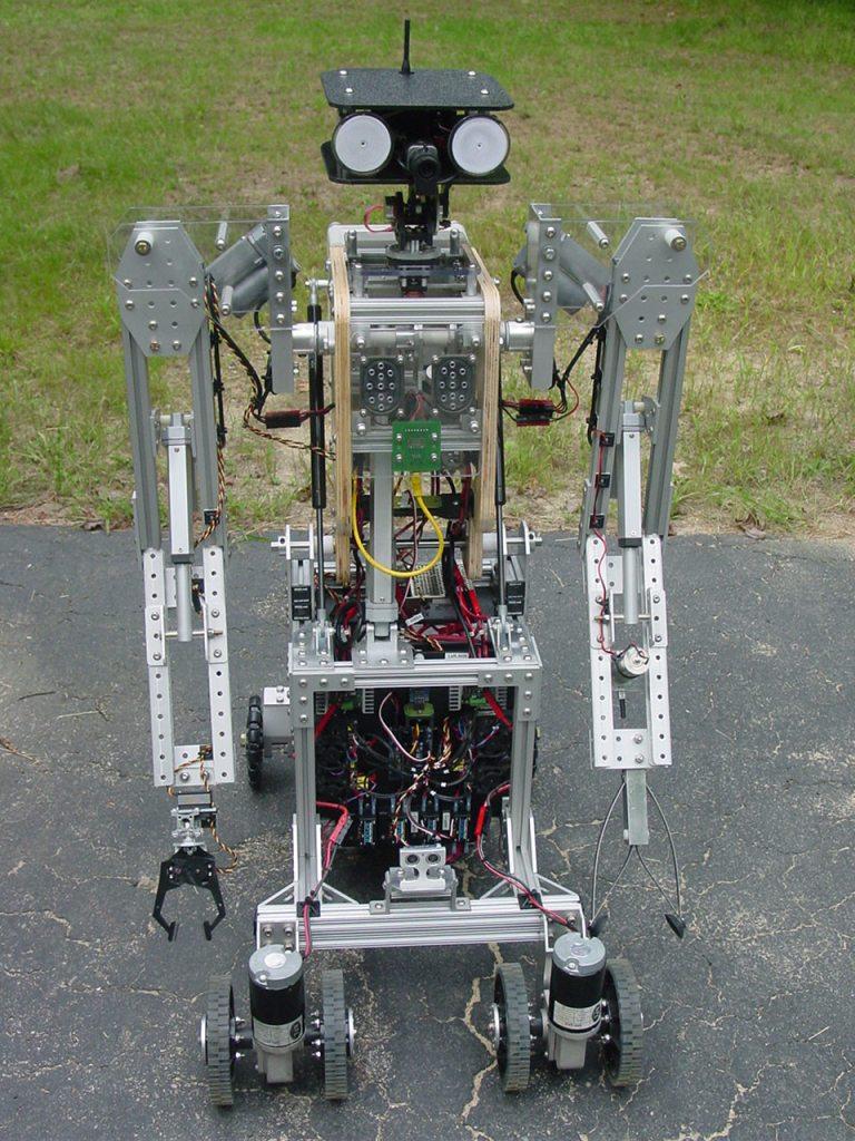

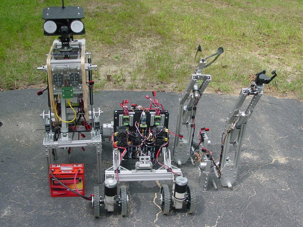


For the last decade or more I've been working on a series of large robots with articulated arms. I just finished the latest version, ARMadeus Mk7. Considered mid-size compared to some of its descendents, it measures 48" tall and weighs 112 pounds. Some of the main components include:
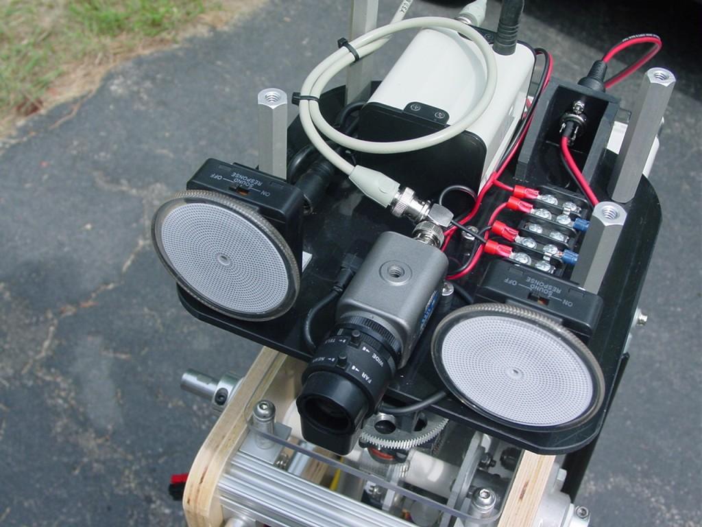
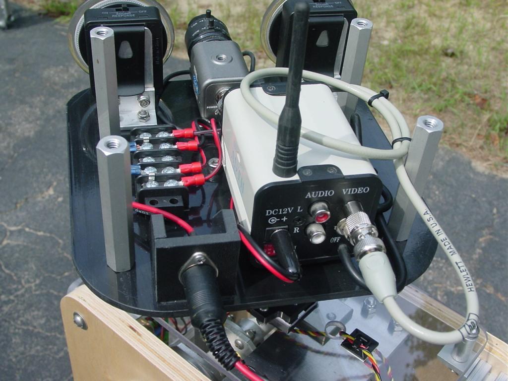
(3) 12V DC gear motors (4) Servos (6) 12V linear actuators (4) IFI Victor 12V speed controllers (2) Sabertooth 2x12 speed controllers (2) IFI Spike H-Bridge relay modules (1) Audio player (1) video camera w/ 2.4GHz transmitter
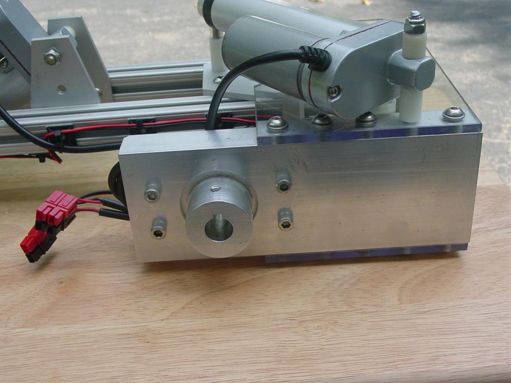
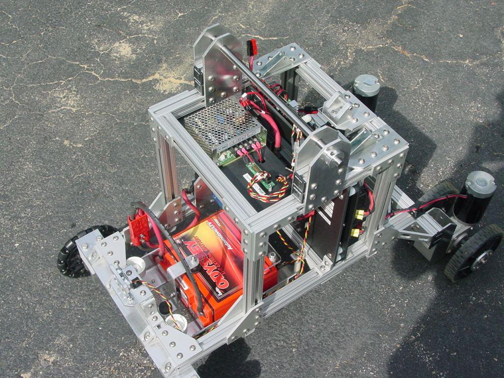
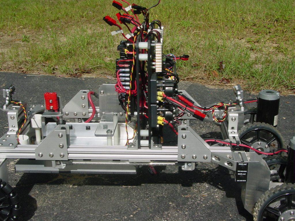
There are two common features that I consider essential when designing large-scale robots, adjustability and modularity. All of the ARMadeus robots have been built using 80/20 aluminum t-slotted extrusions and joining plates. It allows for flexibility in repositioning parts without having to drill holes. The first picture shows the lower 21" wide x 32" long lower chassis and drive train.
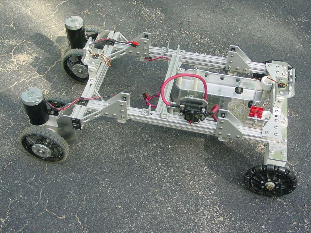
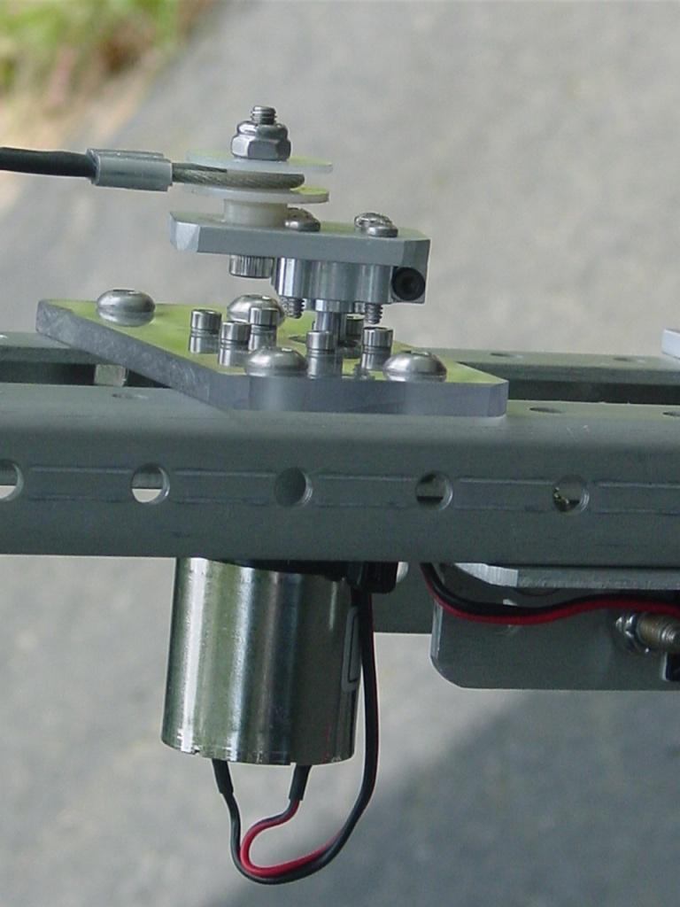
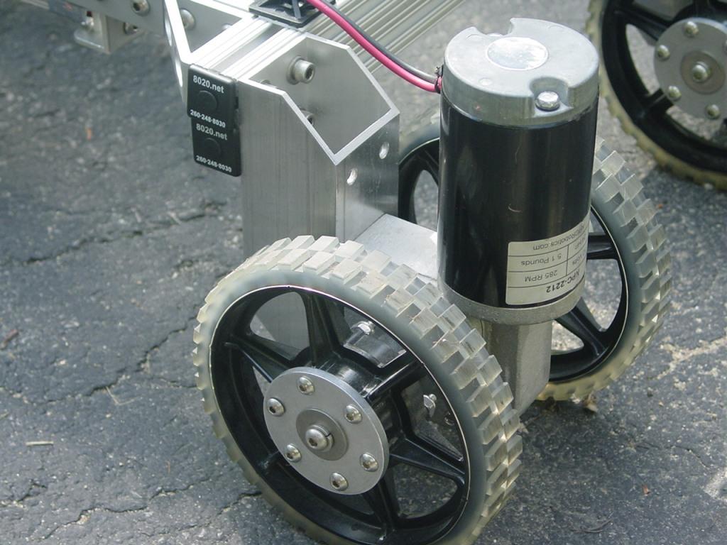
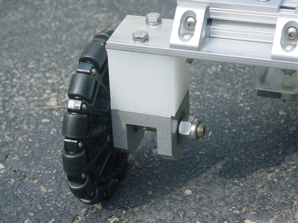
Here's a closeup of one of the drive units, consisting of an NPC 2212 12V 285 rpm gear motor and 2 AndyMark 6" HiGrip wheels.
The rear wheel assembly uses an AndyMark 6" Omni wheel.
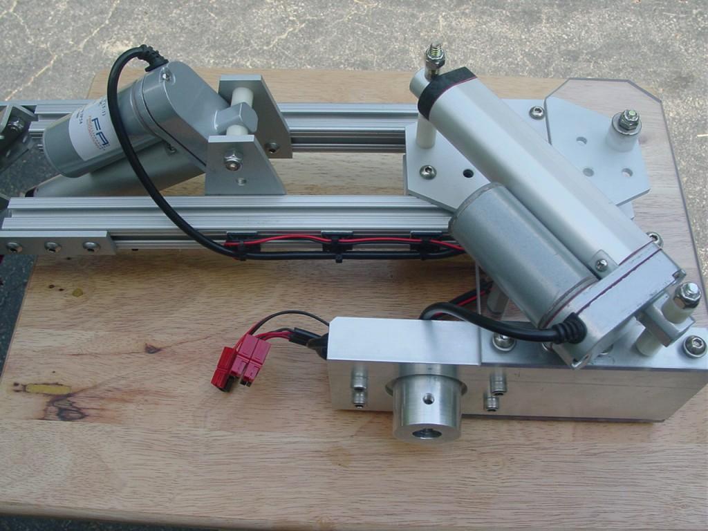
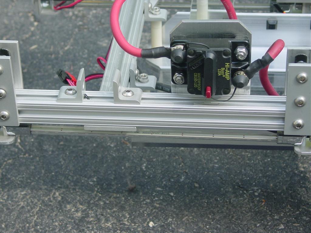
On one side of the chassis is the main power switch/120 Amp circuit breaker. A blue LED light tube for effect lighting can be seen just under the chassis rail.
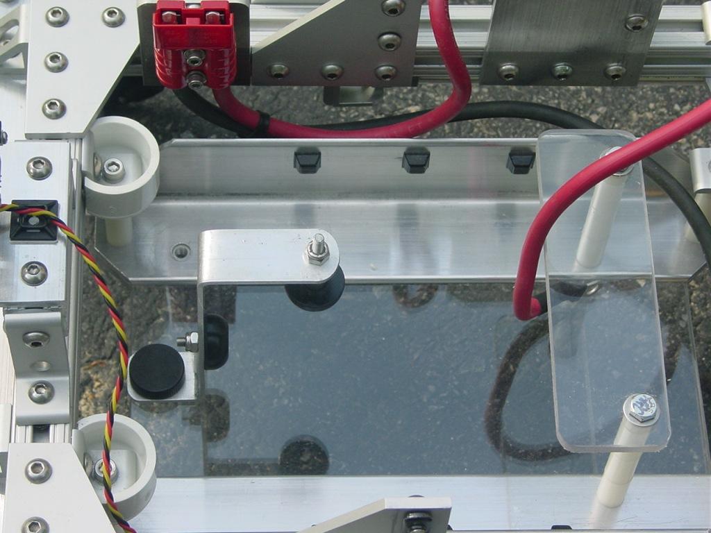
The robot is powered by 12V 17AH Sealed Lead Acid battery. The 15 lb battery is mounted horizontally on a tray near the back of the robot and acts a counterweight when the robot arms and torso are fully extended.
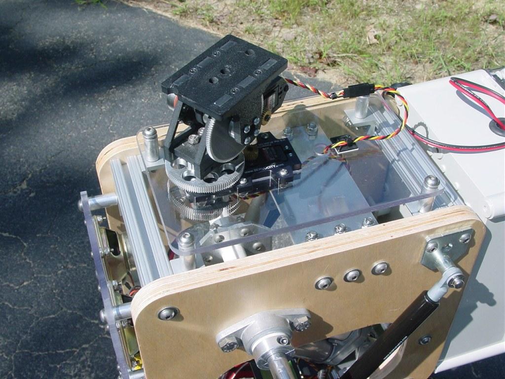
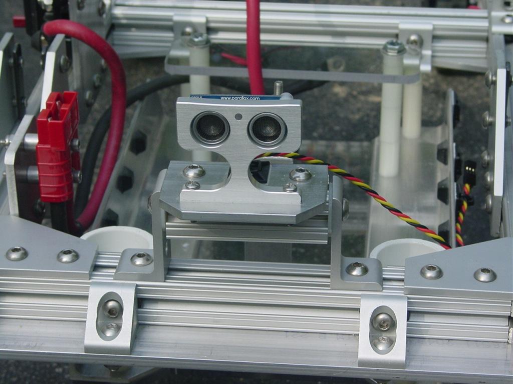
Front and rear Parallax PING sensors are mounted on tilting brackets as shown below.
I will post pictures of the remaining subsystems and the completed robot during the next few days.
Discover more robots

Smarty's Halloween Synthiam - Annabell
Justinratliff's Jd Backpack

Let me be the first to say "wow"!
Can't wait to see the rest.
Sweet,.it's like the adult version.of erector set. I bet that guy will be heavy. I love pictures, hope to.see them soon.
oh cool were did you get the power source eek
The drive motors and battery are available from Robot MarketPlace.
Excellent construction, I can see steel screws on the frame, good choice, I'm looking forward to the rest of the body.
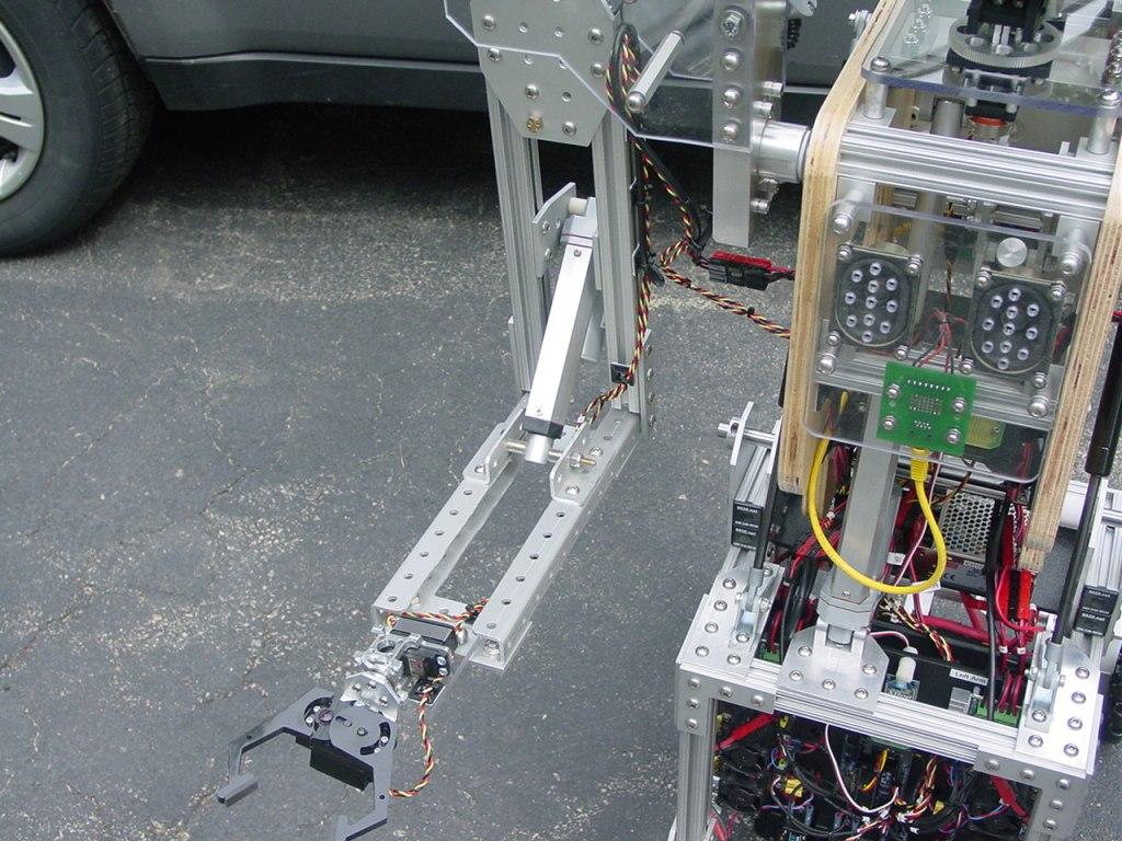
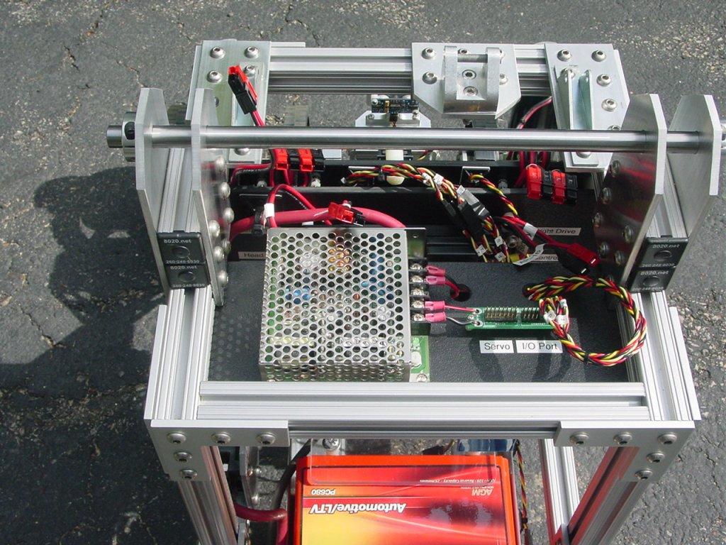
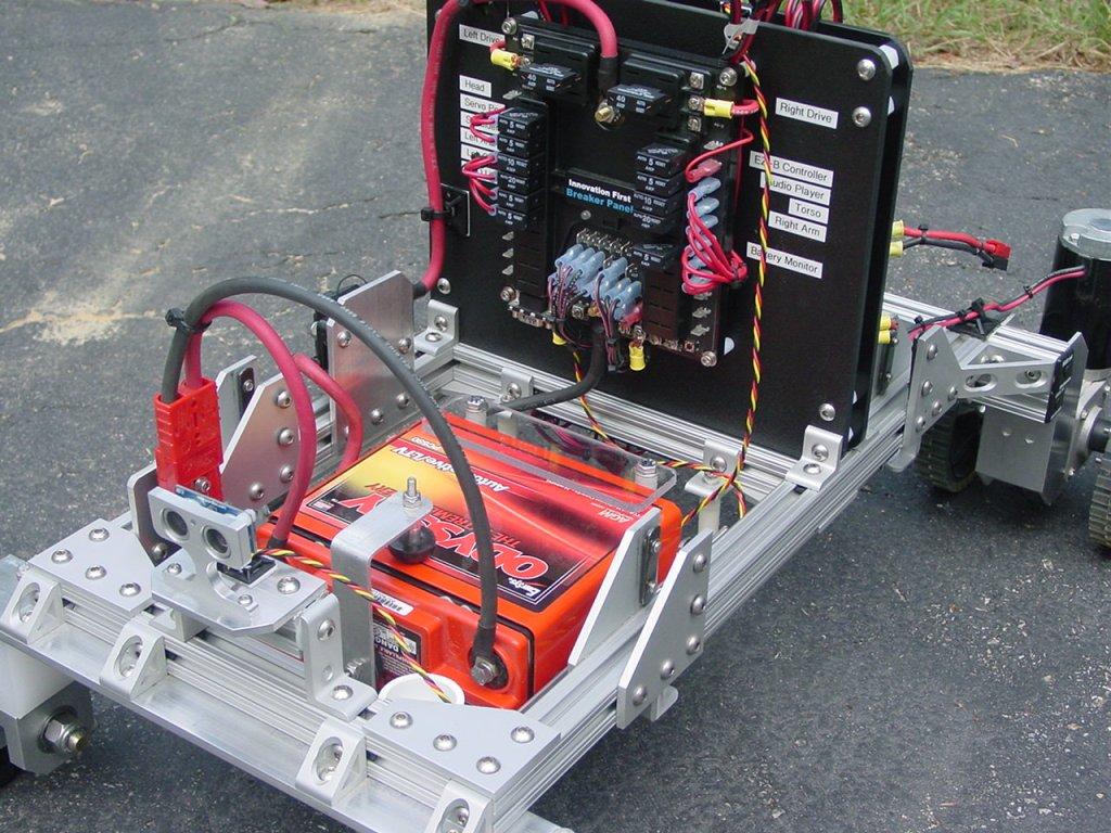
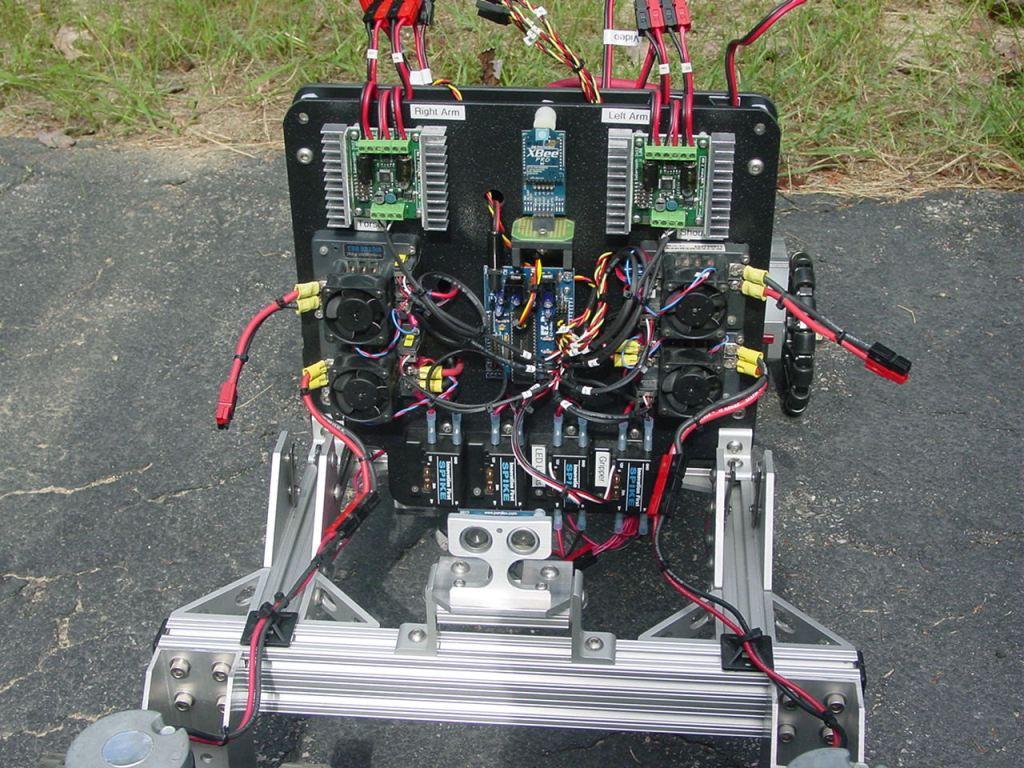
Here is the second installment of the ARMadeus Mk7 build report. Two panels made from 1/4" thick ABS sheets, mounted back to back with 3/4" long threaded nylon spacers, form the electronics module. The rear panel houses a power distribution circuit breaker assembly which feeds 12V power from the battery to the branch circuits for the actuator controls. The front actuator circuits panel contains the six electronic speed controllers and two H-Bridge relay modules along with the EZ-B controller. These components are arranged in a star pattern. The power inputs to the actuator controls are placed towards the center of the panel with the power outputs at the outer edges. Power wires to the actuator controls are routed between the two panels. This keeps the wires short and out of the way. Anderson Powerpole connectors are used extensively for connections to the motors. The whole electronics module drops in place on the lower chassis frame rails between pairs of right angle brackets. The construction method allows the electronics core to be assembled and tested independently of the robot frame.
Rear view of the robot showing the main battery connections to the power distribution panel. Each branch circuit has its own resettable circuit breaker ranging from 5 to 40 Amps.
Front view of the robot showing the actuator control panel of the electronics module. This is where the magic happens. Kudos to DJ and all the folks at EZ Robot. Because of the EZ-B I was able to achieve this much functionality. I am using 17 of the 20 Digital ports and 1 ADC port. I did replace the Bluetooth controller with a longer range XBee Pro. There are 2 Sabertooth 2x12 units at the top of the panel. One is operated in serial mode the other in RC mode. Below the Sabertooths are the vintage IFI 12V Victor 883 speed controllers. The IFI Spike H-Bbidge relay modules are mounted at the bottom of the panel. Two are being used, the other two are spares for possible future expansion.
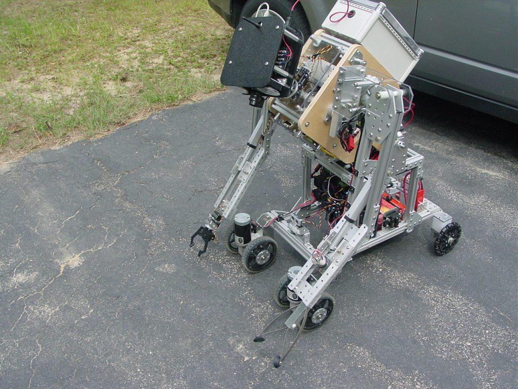
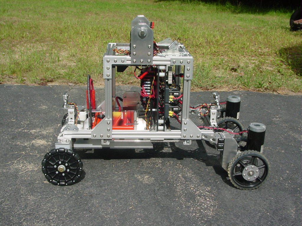
A side view of the robot showing the completed electronics module mounted to the frame.
The next installment will detail the upper chassis featuring a servo power supply and the hip joint between the frame and the torso.
Totally amazing! This construction certainly pass a homologation for marketing, also seems out of a robot factory!
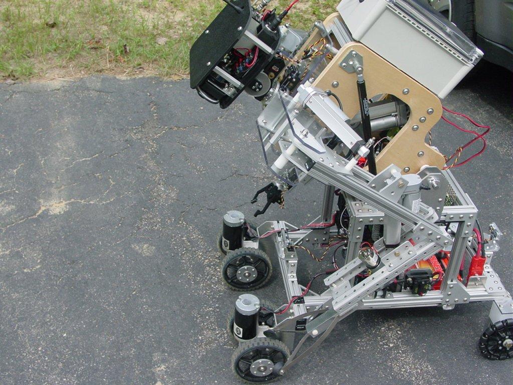
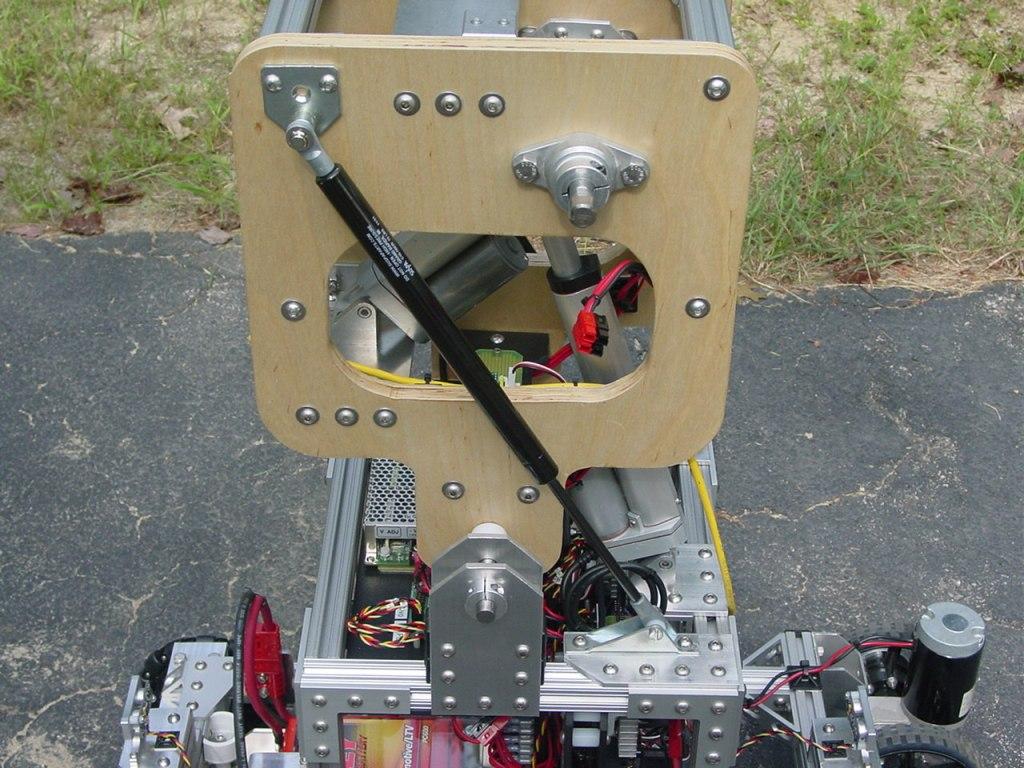
The upper chassis is essentially a cube, 12" on a side, constructed of 80/20 aluminum extrusions and "L" shaped joining plates. It drops into the four pairs of plates on the chassis rails. The hip joint for the torso is made from four 3/16" thick aluminum plates and a 1/2" diameter stainless steel shaft. This where the adjustable nature of the 80/20 system justifies itself for large scale robot projects. It allowed me to easily experiment with and fine tune the positions of the upper chassis and hip joints for optimum range of motion, center of gravity, and clearance with the electronics.
At the back of the upper chassis, I mounted a 5V/5A DC to DC converter on an ABS panel. This supplies more than enough isolated servo power. It also provided an easy access point for servo connections near the geographic center of the robot.
The next photo shows a side view of the completed chassis with a weight of 64 pounds so far.
Up next I will document the torso construction where things start to get interesting with the introduction of moving parts.