
Step 8. Power Regulation.
The three main types of power conversation units that we are going to talk about here, which are Buck converters, regulators, and inverters.
Voltage Regulators.
There are three popular types of voltage regulators...
"Step Down" which reduces power,
"Step Up" which increases power,
and "Step Up / Step Down" which can both increase or reduce power.
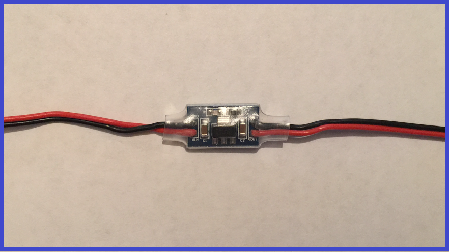
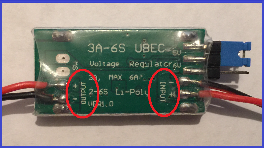
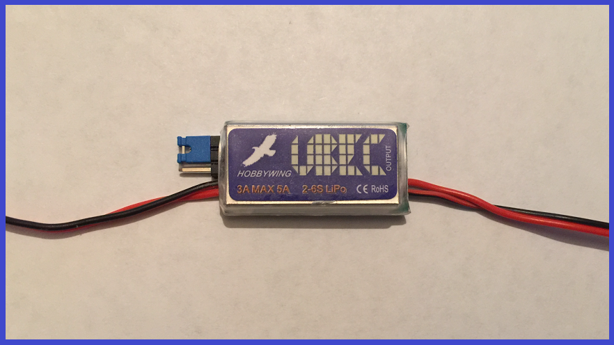
What these electronic devices do, is maintain the voltage of a power source within acceptable limits. Regulators can be found in many electronic devices, and their job is to maintain voltages within a set range that can be tolerated by the electronic device, using that set voltage. The EZ-B v4 has regulators built inside which reduces the incoming power down to 3.3v on the analog, UART, i2c, and camera power pins.
Voltage regulators have an "input" and an "output" which are usually marked on the regulator. The input, is where you would connect your power source to, where this power is then converted. The device that needs the power is connected to the output, and receives the adjusted power.
Keeping with the EZ-B, let's lay out a couple of real world examples.
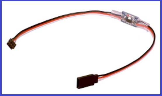
You have a 7.5v 20 amp mains power supply that is powering your EZ-B, but you may want to connect an ultrasonic distance sensor to it. These connect to the digital ports, but the sensors are 5v, and your 7.5v power supply is going straight through to the power pins (unregulated). This is where an external 5v step down voltage regulator will come in (like the ones seen above and below)...
1.) You plug the "Input" leads in to the EZ-B digital pins, (power comes out of the EZ-B, and "IN" to the regulator).
2.) The sensor is connected to the "Output" leads, (power comes "OUT" of the regulator, to the sensor).
3.) You power up the EZ-B and 7.5 volts are fed to the regulator, where it reduces the voltage down to 5 volts, then feed the sensor with the correct 5 volts.
Now there is one thing to keep in mind when using regulators.
We use the same 5v regulator we used above, to reduce the power of the EZ-B itself, instead of connecting it to the digital pins... no problem. Your mains power supply is feeding 7.5v to the 5v regulator, which now reduces 7.5 volts to 5 volts. 5 volts will now power the EZ-B. The EZ-B will power up okay as the voltage is over the minimum 4.5v requirements, and the sensor will receive the 5 volts (5v is now going in to the EZ-B, and 5v is coming out of the digital power pins).
Now we connect 6 heavy duty servos to the EZ-B. The servos will work with 5 volts, so no problem there. We now move all of the servos at the same time... oops, what happened? The EZ-B has browned out. What happened?
Remember step 1? AMPS!!! The servo inrush current draw for all 6 servos moving at the same time is (for example) 18 amps.
It turns out that the 5v regulator is only rated to draw 5 amps, and will now only offer 5 amps maximum.
You are feeding the regulator 7.5v that it reduced to 5v output. But, you are also feeding 20 amps to the regulator that is only rated for 5 amps output. This is sometimes called a bottleneck. The regulator is restricting the amount of available current, and now not passing enough to the EZ-B and the servos.
So, voltage regulators are very useful when used with the correct application. They come in various sizes, some have connectors on them, some don't, and there are different input and output voltage and current options available. Below is a link for the EZ-Robot inline regulator that is rated for 16v input, 1 amp draw, and 5v output. It also has connectors on it which makes it a very easy "plug 'n' play" device.
www.ez-robot.com/Shop/AccessoriesDetails.aspx?prevCat=103&productNumber=98
Buck Converters.
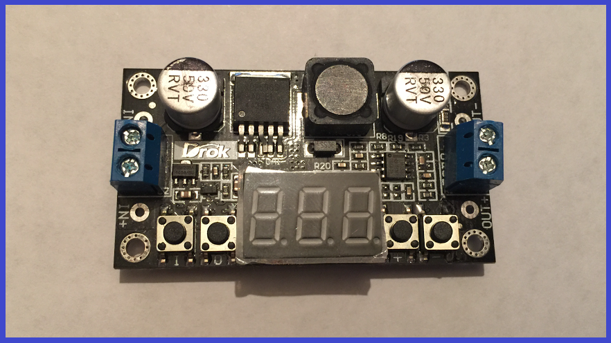
Buck converters are a form of switching regulator which means they are more efficient, but can cost slightly more. These are very similar to voltage regulators in that they can step up, or step down incoming power, but there are a few differences. Apart from their form factor and size, the output voltage from a Buck converter can be changed. Some have a momentary push buttons and others have potentiometers which, when pushed or adjusted, can change the voltage output. Many have a visual display so you can see what the input voltage is, and the output voltage so you can adjust it to your requirements.
The following, is a short step by step guide for using a step down Buck converter with a momentary push button voltage selectors and an LED display, which using a battery will power a 3v LED strip.
1.) Connect the positive and negative wires from the battery to the correct "Input" terminals on the buck converter (do not connect the device at this point, as the buck converter my be set at a default voltage too high for your device to handle).
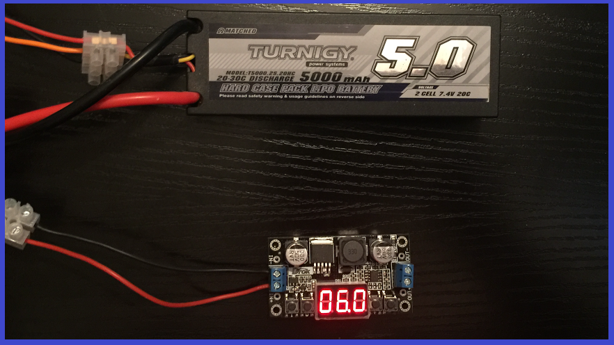
2.) You will now see the input voltage of the battery. Press the button to the right of the display to display the voltage output.
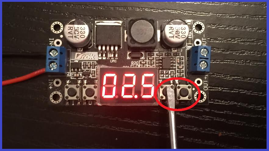
3.) With a small screwdriver, turn the screw on the potentiometer, or as seen below, press the "increase" or "decrease" voltage button. You should now see the display values change. If the buck converter has a screw and the numbers don't change when you turn it, turn the screw the other way (it may take a few turns). When your desired voltage is being displayed, stop turning the screw.
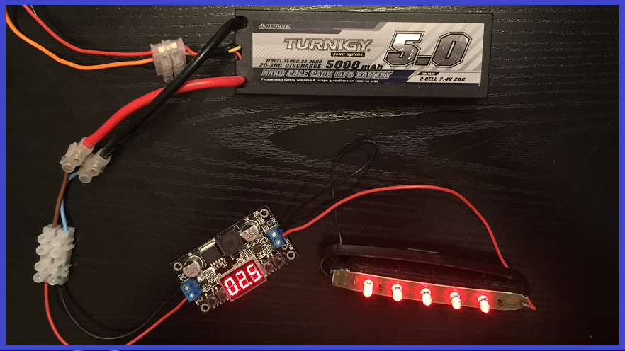
4.). Disconnect the battery, and connect the wires for the device that needs to be powered to the "Output" terminals, making sure the positive and negative wires are connected to the correct output terminals.
5.) Reconnect the battery, and the device will now receive the correct, regulated power.
In the image, the setting is an output for 2.5v which is fine for powering 3v LED's. If you think about it, LED's powered by two alkaline batteries in series will not always get the full 3 volts on offer, as the alkaline's slowly deplete as they are used.
As with voltage regulators, there are different options when choosing a buck converter, such as maximum and minimum voltage input, minimum and maximum output voltage, and maximum current draw. Some buck converters may have a small heat sink fitted and some will not, so you may need to fit one depending on the power requirements used.
Power Inverters.
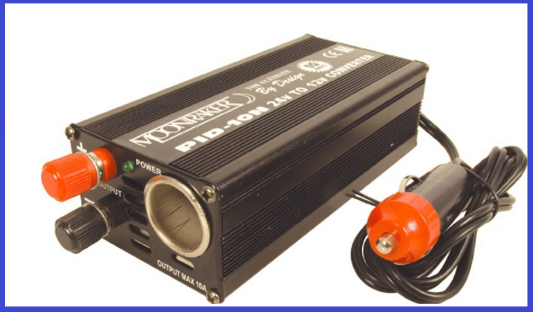
A power inverter is designed to convert DC to AC. For example, the input power to the inverter would be a DC source from a battery. This is then converted to AC, so an AC powered device like a TV that is usually powered from the mains supply, can operate. The efficiency of many inverters is around the 80% mark and sometimes have built in low battery voltage protection.
The other part of a power inverters design, is to increase output voltage from a lower input power source. You may know that a taser weapon used to subdue bad guys can produce many volts, (around 50.000 volts and 133mA output), but it is only powered buy a 9 or 12VDC battery at 4.8 amps input. This is because a taser has a built in power inverter.
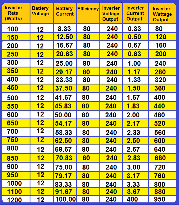
One final thing about inverters, is the current that gets drawn from the power source when powering an AC device. When you look at the specifications for inverters, the numbers given are usually Watts, and it's important to know that this in input, not output.
As an example, we need to run a 500 Watt AC device, but if you look at the table below, on the column to the right, you will not see a 500 watt value. However, on the next line, you will see a value of 520, and a current output of 2.17 amps. If you now go to the inverters rated wattage row, you will see a value of 650 watts which would a good place to start.
That covers the basics for power regulators, and should have hopefully explained what these devices do, and how to use them.
Normally, where there is power, there is wire. The next step will go through how to choose the correct wire for your projects.

Thanks for this info. Still not sure why everything says it will handle 20plus servos because power wise, they cant. also a 20amp fuse will probably to blow before ez-b blows. this would be great in the specs!!
Thanks again
Scott
I'm not an expert, but there is common sense too.
Not all servos are equal: there are small torque and high torque servos, there are cheap servos (bad electronics, counterfeiter etc) and good servos (good engineering) and smart servos (with micro-controller e.g. Dynamixel with temperature, load, torque control).
Servos/motors have different current rates e.g. idle, torque stall, peak, inrush.
Some setups don't accommodate the Inrush/Peak current. Inrush Current is commonly used to describe the current that is required to energize an AC powered device when first applying voltage and power to it. If you have all your servos moving at same time you have a Inrush current during a brief period.
Some batteries have high discharges rates for example a lipo battery with 1000 mAh and a C=20 can handle 20 amps, but a niMH (AA) can't handle 20 Amps so the battery plays an important role.
And last not all fuses are equal there are quick-acting and time-lag (slow) a slow fuse can handle as much as 10 times the current for a brief period before blowing up...
Without knowing all details we can't make assumptions.
I recommend using EZ-Robot HDD digital servos for prototyping you product development, because they're the highest efficiency that you'll find. PTP is correct, in that your post may be assuming a specific servo experience, which is impossible to generalize. The EZ-B can provide power to entire InMoov large servo configurations. Even the EZ-Robot JD humanoid uses an EZ-B v4 and has 14 hdd servos and powers off a single 7.4v battery. This conversation of power requires explicit details of the hardware selected for your product development - as it cannot be generalized.
If you have questions regarding the EZ-B v4 manufactured by EZ-Robot, then you can visit their website at www.ez-robot.com to contact them directly. Otherwise, the opensource hardware and software for the EZ-B v4 design is available in the Synthian GitHub link at the footer of this website. Lastly, there's a number of supported hardware platforms for ARC in the Getting Started link on this website. Many options to ensure you experience positive results with your product development.