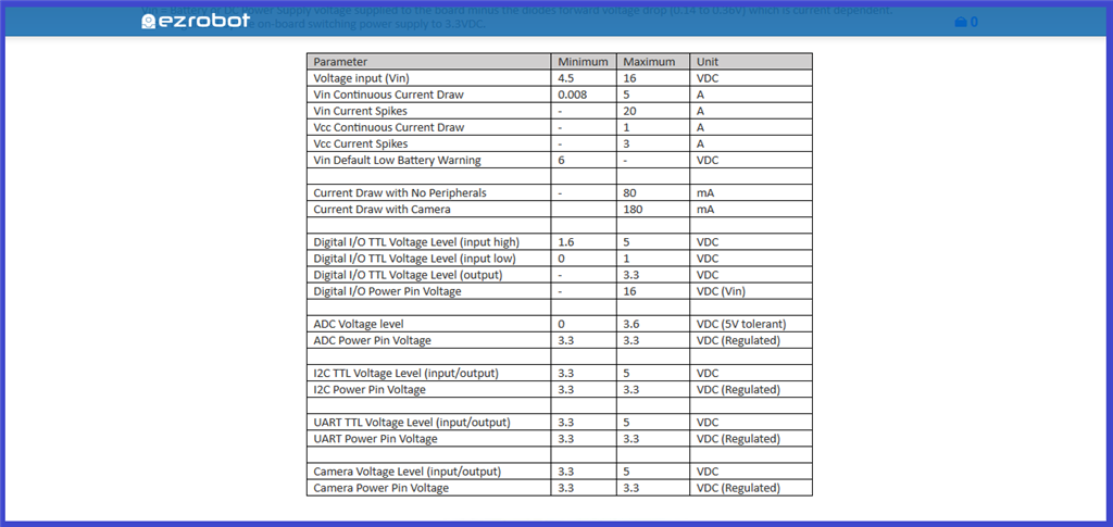
Step 3. EZ-B v4 Port Pins.
Electrical details for the EZ-B v4...
A break down of the EZ-B v4 pin specifications.
Vin (Voltage input) = 4.5-16VDC Unregulated input voltage (Digital port section Red power pins)
Vcc (Voltage Common Collector) = 3.3VDC Regulated voltage (Analog port section Red power pins)
VDC: meaning "Volts of Direct Current".
The "minimum" input voltage from a power source that powers the EZ-B v4 is 4.5VDC.
The "maximum" input voltage from a power source that powers the EZ-B v4 is 16VDC.
The "maximum" continuous current draw through the EZ-B v4, is 5 amps. (limited by reverse polarity protection).
The "maximum" momentary power spike through the EZ-Bv4 is 20 amps (limited by 20A ATM Fuse in power base or power harness).
The "maximum" continuous current draw on the EZ-B v4 Vcc (3.3VDC) regulated supply (middle red power pins on analog ports), is 1 amp.
The "maximum" momentary power spike on the EZ-B v4 Vcc (3.3VDC) regulated supply (middle red power pins on analog ports), is 3 amps.
The EZ-B's current draw with no devices connected to it, is 80 milliamps. With the EZ-Robot camera connected, it's 180milliamps.
The digital I/O pin (white signal pin) voltage output "high" level, is 3.3VDC.
The digital I/O pin (white signal pin) voltage output "low" level, is 0VDC.
The digital I/O pin minimum voltage input "high" level is 1.6VDC.
The digital I/O pin maximum voltage input "high" level is 3.3VDC (5V tolerant).
The digital I/O pin minimum voltage input "low" level is 0VDC.
The digital I/O pin maximum voltage input "low" level is 1VDC .
The source/sink limitation from a single digital signal pin is 10milliamps. (up to 120mA total for all pins combined).
The ADC reads voltage levels from 0-3.6VDC but is 5V tolerant (voltage from 3.6V to 5V will likely show up as 3.6VDC).
The ADC signal pin "minimum" voltage level, is 0VDC.
The ADC signal pin "maximum" input voltage level, is 3.6VDC (5v tolerant).
The ADC power (centre) pin voltage, is 3.3VDC (regulated).
The i2c communication voltage level is 3.3VDC. (5V tolerant) The i2c power pin voltage, is 3.3VDC (regulated).
The UART (port 0) communication voltage level, is 3.3VDC (5V tolerant).
The UART (port 0) power pin voltage, is 3.3VDC (regulated)
The Camera TTL communication voltage is 3.3VDC. (5V tolerant)
The Camera power pin voltage, is 3.3VDC (regulated)
Where it is noted that the digital power pins can handle 5 amp per digital pin, this is combined constant amperage of 5A for all the digital power pins. The maximum amperage for each pin is 2 amps per pin. While you can have a spiked (pulsed) current up to 20A, the ez-bv4 is only rated for 5A of constant current.


Thanks for this info. Still not sure why everything says it will handle 20plus servos because power wise, they cant. also a 20amp fuse will probably to blow before ez-b blows. this would be great in the specs!!
Thanks again
Scott
I'm not an expert, but there is common sense too.
Not all servos are equal: there are small torque and high torque servos, there are cheap servos (bad electronics, counterfeiter etc) and good servos (good engineering) and smart servos (with micro-controller e.g. Dynamixel with temperature, load, torque control).
Servos/motors have different current rates e.g. idle, torque stall, peak, inrush.
Some setups don't accommodate the Inrush/Peak current. Inrush Current is commonly used to describe the current that is required to energize an AC powered device when first applying voltage and power to it. If you have all your servos moving at same time you have a Inrush current during a brief period.
Some batteries have high discharges rates for example a lipo battery with 1000 mAh and a C=20 can handle 20 amps, but a niMH (AA) can't handle 20 Amps so the battery plays an important role.
And last not all fuses are equal there are quick-acting and time-lag (slow) a slow fuse can handle as much as 10 times the current for a brief period before blowing up...
Without knowing all details we can't make assumptions.
I recommend using EZ-Robot HDD digital servos for prototyping you product development, because they're the highest efficiency that you'll find. PTP is correct, in that your post may be assuming a specific servo experience, which is impossible to generalize. The EZ-B can provide power to entire InMoov large servo configurations. Even the EZ-Robot JD humanoid uses an EZ-B v4 and has 14 hdd servos and powers off a single 7.4v battery. This conversation of power requires explicit details of the hardware selected for your product development - as it cannot be generalized.
If you have questions regarding the EZ-B v4 manufactured by EZ-Robot, then you can visit their website at www.ez-robot.com to contact them directly. Otherwise, the opensource hardware and software for the EZ-B v4 design is available in the Synthian GitHub link at the footer of this website. Lastly, there's a number of supported hardware platforms for ARC in the Getting Started link on this website. Many options to ensure you experience positive results with your product development.