
Step 7. Multimeters.
A Volt Meter.
Measures the potential difference, in Volts, between the two points being measured. The voltmeter gets connected in "parallel". It has a high resistance in order to divert the majority of current through the main circuit.
Ammeter.
Measure the current of the circuit in Amps. It essentially counts the electrons as they pass through the ammeter. The ammeter is connected in "series". It has a very low resistance so as not to disturb the functioning of the circuit too much.
Multi-meter.
A device that has the options to measure both voltage, and amperage. Basically, the two meters mentioned above, in one unit. They can also measure resistance.
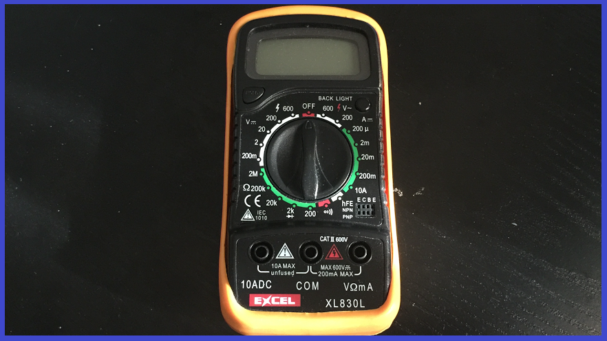
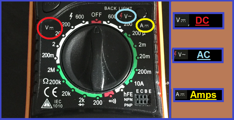
This step will explain how to measure voltage and amperage with a multi-meter. The thing to know before you start, is that there are usually 3 functions which will read DC (direct current), AC (alternating current), and A (amps). For reading voltage, the multi-meter used in this example has three different symbols for AC, DC and Amperage, which is seen in the picture below...
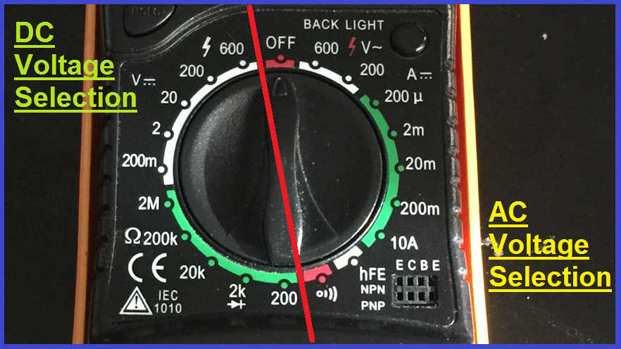
Some multi-meters are auto ranging, but this one is done manually, so it has different voltage ranges for DC on the left of the meter, and AC on the right...
The three terminals on the bottom of the multi-meter are as follows...
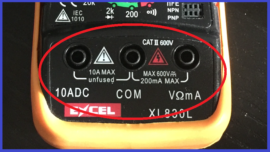
10 ADC Can measure up to 10 amps before the fuse between the "10ADC" and "COM" terminals blows if the 10 amp limit is exceeded.
COM Is the common terminal for the black probe.
V mA Can measure up to 200 milliamps before the fuse between the "V mA" and "COM" terminals blows before the 200 milliamp limit is exceeded.
Measuring "DC" Voltage.
First, we will start by measuring the voltage of a 1.5v battery (DC power supply). This is essentially a "parallel" circuit we are creating... a power source powering one device directly.
1.) Connect the black probe jack in to the "COM" terminal, and the red probe jack in to the "V mA" terminal.
2.) Move the multi-meters selector to the DC side of the meter, and select "2V DC" so we set the meters voltage reading to the next highest DC reading (we know the battery is 1.5v, as it says so on the battery).
3.) Touch the black probe to the negative "-" terminal, then the red probe to the positive "+" terminal of the battery. You should now get a reading from the battery...
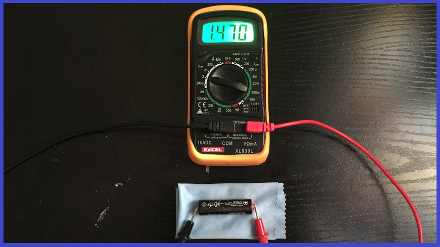
We get a reading of a little over 1.4 volts. What happens though, if you turn the selector to a higher voltage reading? Well have a look at the following images...
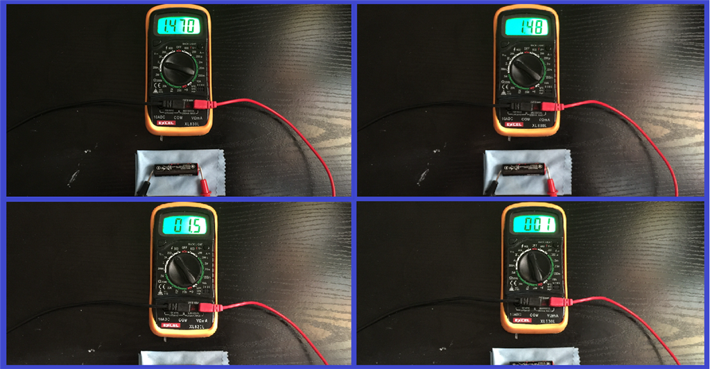
All that is happening here is the decimal place is decreasing, (1.470v, 1.48v, 1.5v, 1v), which as you can see, will also mean that the readings will lose accuracy.
Measuring the voltage of a DC wall adapter is no different. Set the voltage reading dial on the meter to the next highest setting than what the voltage output is from the adapter. Place the red probe in to the centre of the adapter jack, and touch the black probe to the outside of the jack...
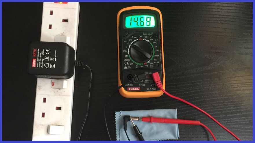
you see a reading of 14.69v in the image above, that is reading the adapters output, which is 15V.
Measuring "AC" Voltage.
Now we will measure the voltage from a mains wall outlet (AC power supply).
This is just as easy as testing DC voltage, but much more care should be taken, as we are dealing with the higher power AC output. This example will be measuring a direct 240v mains output from a UK wall outlet.
1.) Turn off the wall outlet power.
2.) Move the meters dial to the AC side, and select the 600V AC option (we know we are measuring 240V, so we go to the next highest AC meter read setting... in this case, 600V AC).
3.) Insert the probes in to the wall outlet (or cable in this example) and... "Wait a minute, are you going to say turn the power on? what way do the red and black probes go?" Well, it doesn't matter. AC by definition, is alternating current, so it is not polarized. So with that being said... turn on the power.
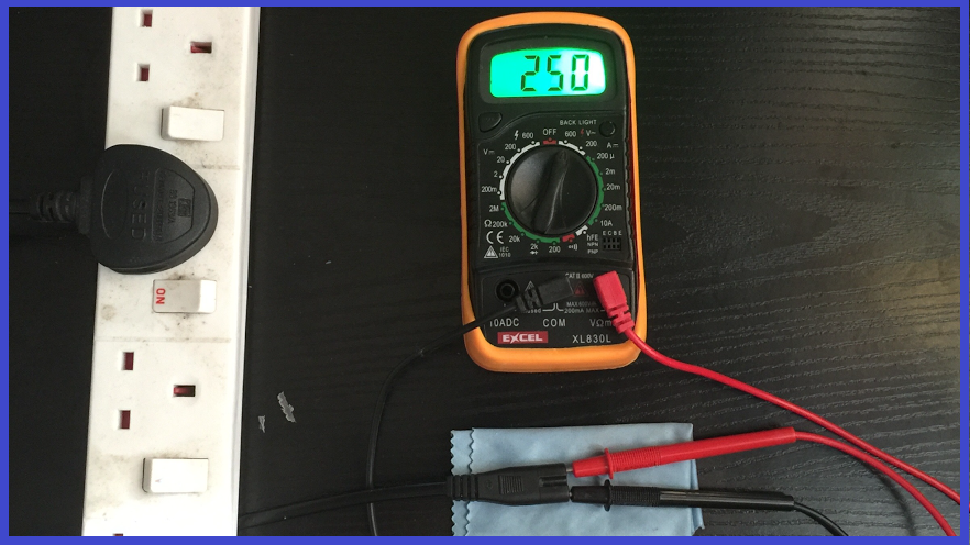
4.) In the image above, you will see a reading of 250V AC, not 240V AC as this is because AC is not regulated, so this reading is indeed, correct.
Measuring Amperage.
This is done differently to measuring voltage where we create a "parallel" circuit, as we will now create a "serial" circuit... one power source powering two devices chained together.
Here, we will measure the amp draw on an LED strip powered off two 1.5V batteries in series (=3 volts).
1.) On the multi-meter, plug the black probe jack in to the "COM" terminal, and the red probe in to the "10ADC" terminal.
2.) Move the dial to the "10A" option.
3.) On our LED circuit, we need to make a break in the positive wire so the meter can be chained to it (parallel). Cut the wire, strip the two ends, and wrap the striped wire coming from the battery around the red probe. The wrap the stripped wire going to the LED around the black probe (if this is reversed, you will still get a reading, but you will see a minus (-) symbol telling you that it is reversed.
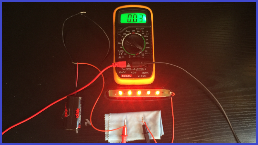
4.) Once power is applied, we see that we get a reading of 0.03. As the dial is set to read 10A maximum, the 0.03 equals to 30mA (30 milliamps).
Reading current draw this way is great for deciding what fuse amperage to go for to protect your circuit, and your robot.
If you are unsure of what the voltage or amperage range of the device you are measuring is, start from the highest reading setting on the meter, then turn the dial to reduce the maximum reading. If it is set too low, you will more than likely get an "error" reading, or worse case, blow the fuse in the meter to protect it.
So with the basics covered with how to use a multi-meter to read amps and voltage, this will guide you away from supplying too little or not enough voltage and current to your motors, servos, sensors, and of course, LED lights.
NOTE: When measuring power with a meter, it must be remembered that you are measuring potentially dangerous power. For example, you could be worried about getting an electric shock from measuring an AC voltage or current from a wall outlet. The thing is, that is what these devices are made to do, but never the less, great care should be taken. If you are not sure or nervous about using a multi-meter, or indeed working on any electrical system or device...PLEASE CONSULT AN EXPERT OR QUALIFIED ELECTRICIAN.
With that said, let's move on to power regulation options, in the next step.

Thanks for this info. Still not sure why everything says it will handle 20plus servos because power wise, they cant. also a 20amp fuse will probably to blow before ez-b blows. this would be great in the specs!!
Thanks again
Scott
I'm not an expert, but there is common sense too.
Not all servos are equal: there are small torque and high torque servos, there are cheap servos (bad electronics, counterfeiter etc) and good servos (good engineering) and smart servos (with micro-controller e.g. Dynamixel with temperature, load, torque control).
Servos/motors have different current rates e.g. idle, torque stall, peak, inrush.
Some setups don't accommodate the Inrush/Peak current. Inrush Current is commonly used to describe the current that is required to energize an AC powered device when first applying voltage and power to it. If you have all your servos moving at same time you have a Inrush current during a brief period.
Some batteries have high discharges rates for example a lipo battery with 1000 mAh and a C=20 can handle 20 amps, but a niMH (AA) can't handle 20 Amps so the battery plays an important role.
And last not all fuses are equal there are quick-acting and time-lag (slow) a slow fuse can handle as much as 10 times the current for a brief period before blowing up...
Without knowing all details we can't make assumptions.
I recommend using EZ-Robot HDD digital servos for prototyping you product development, because they're the highest efficiency that you'll find. PTP is correct, in that your post may be assuming a specific servo experience, which is impossible to generalize. The EZ-B can provide power to entire InMoov large servo configurations. Even the EZ-Robot JD humanoid uses an EZ-B v4 and has 14 hdd servos and powers off a single 7.4v battery. This conversation of power requires explicit details of the hardware selected for your product development - as it cannot be generalized.
If you have questions regarding the EZ-B v4 manufactured by EZ-Robot, then you can visit their website at www.ez-robot.com to contact them directly. Otherwise, the opensource hardware and software for the EZ-B v4 design is available in the Synthian GitHub link at the footer of this website. Lastly, there's a number of supported hardware platforms for ARC in the Getting Started link on this website. Many options to ensure you experience positive results with your product development.