


Now I have the EZ-B kit and the Hearoid it's time to start my Showcase thread.
I still haven't decided on a name for him yet, all suggestions are welcome.
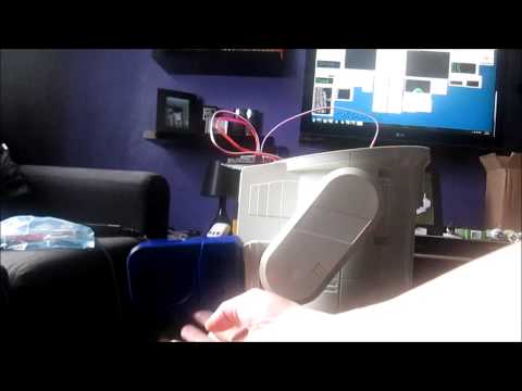
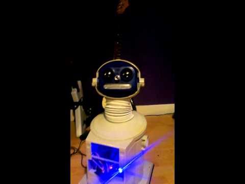
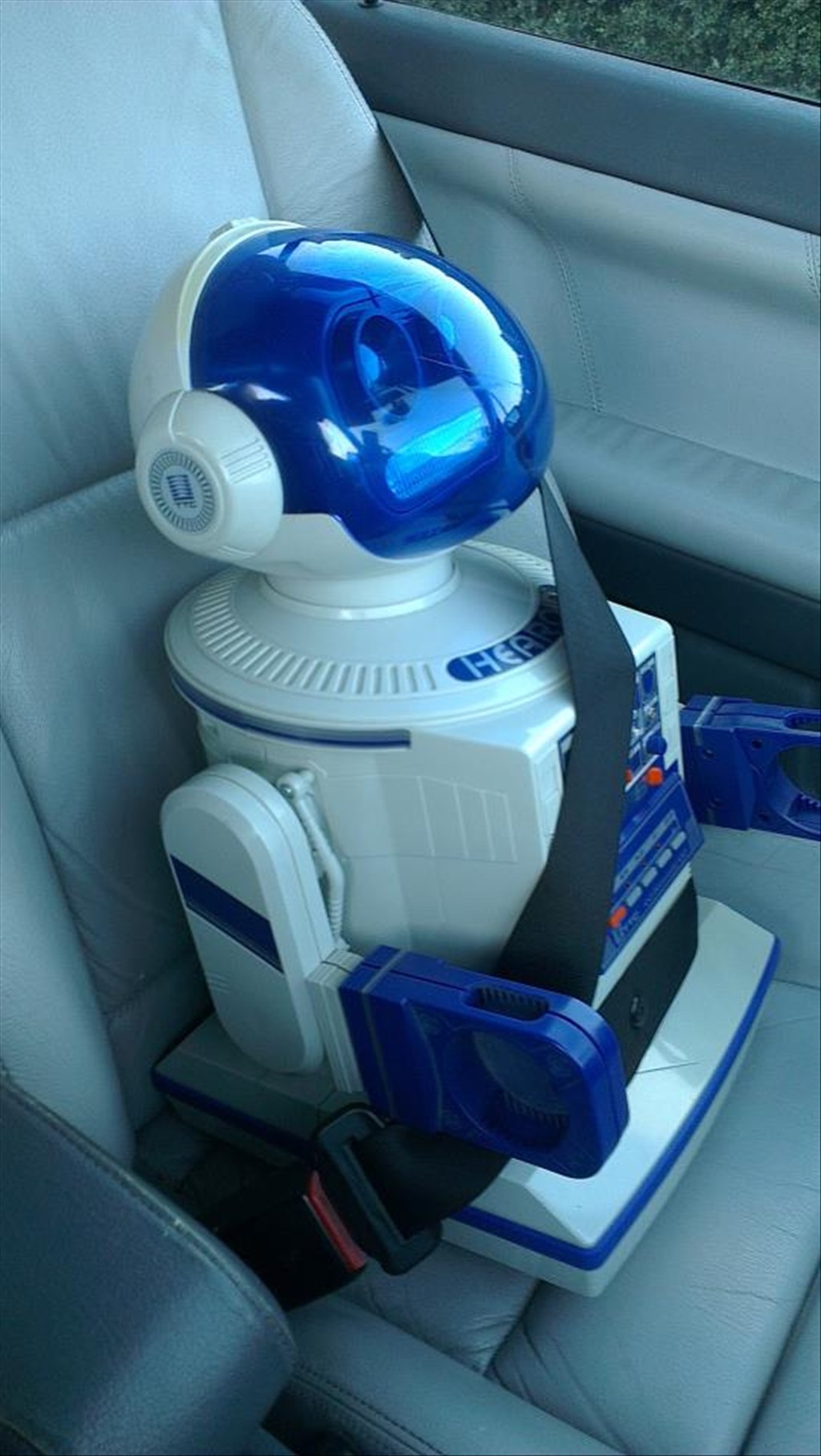
I won this robot on ebay weeks ago, for the past 2 weeks he has been waiting for me to collect him...
Today was the day, a road trip to pick him up and bring him back to his new home...
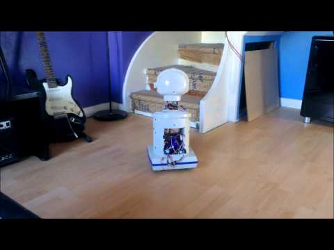
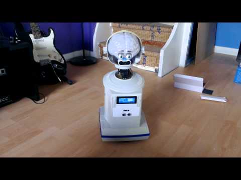
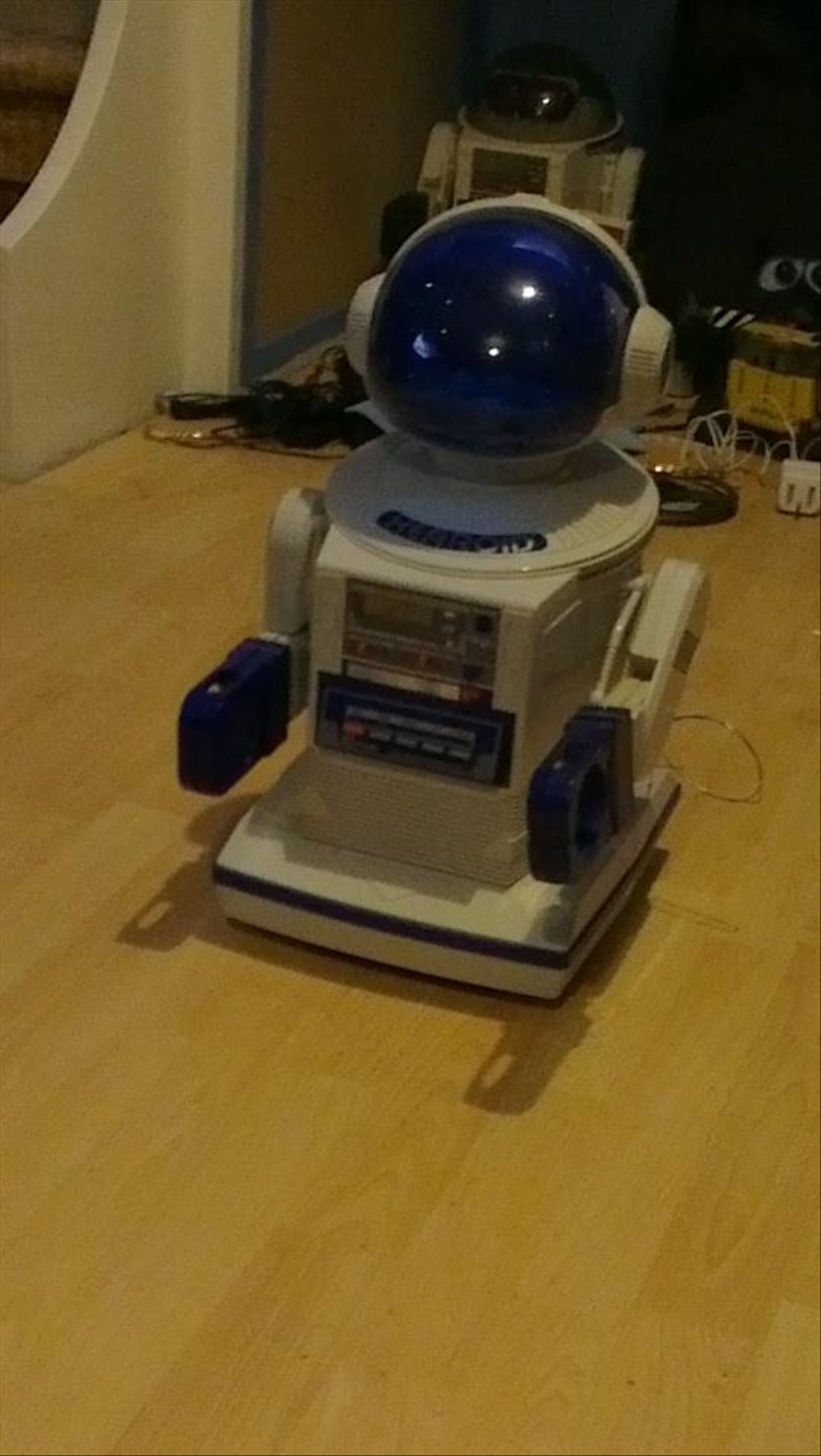
In his new home (with Omnibot and Wall-e in the background totally unaware they are next in line to be opened up)
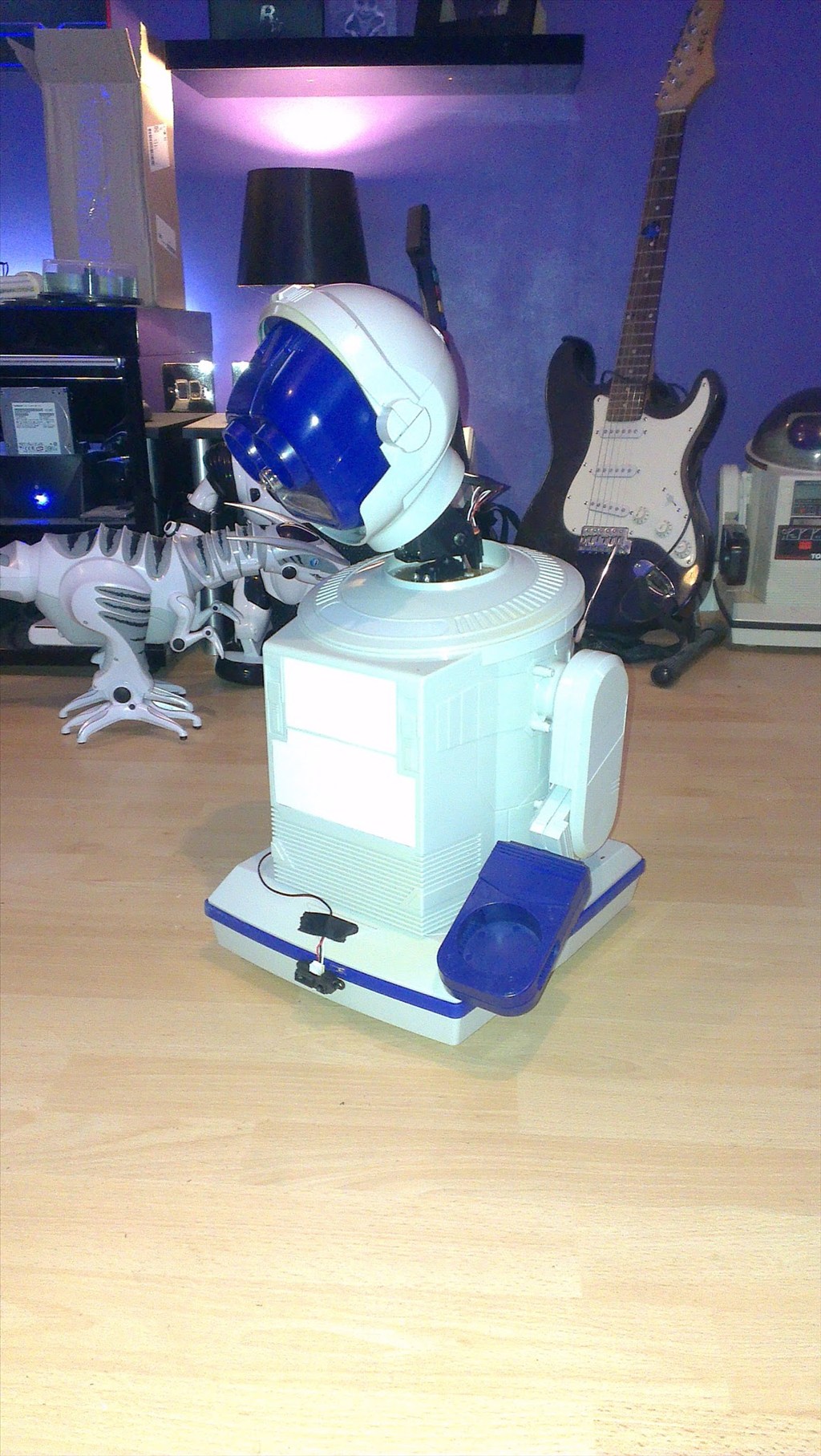
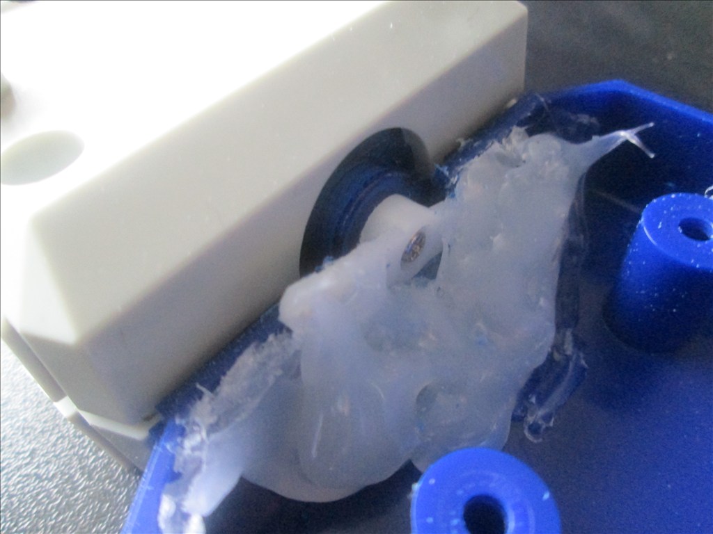
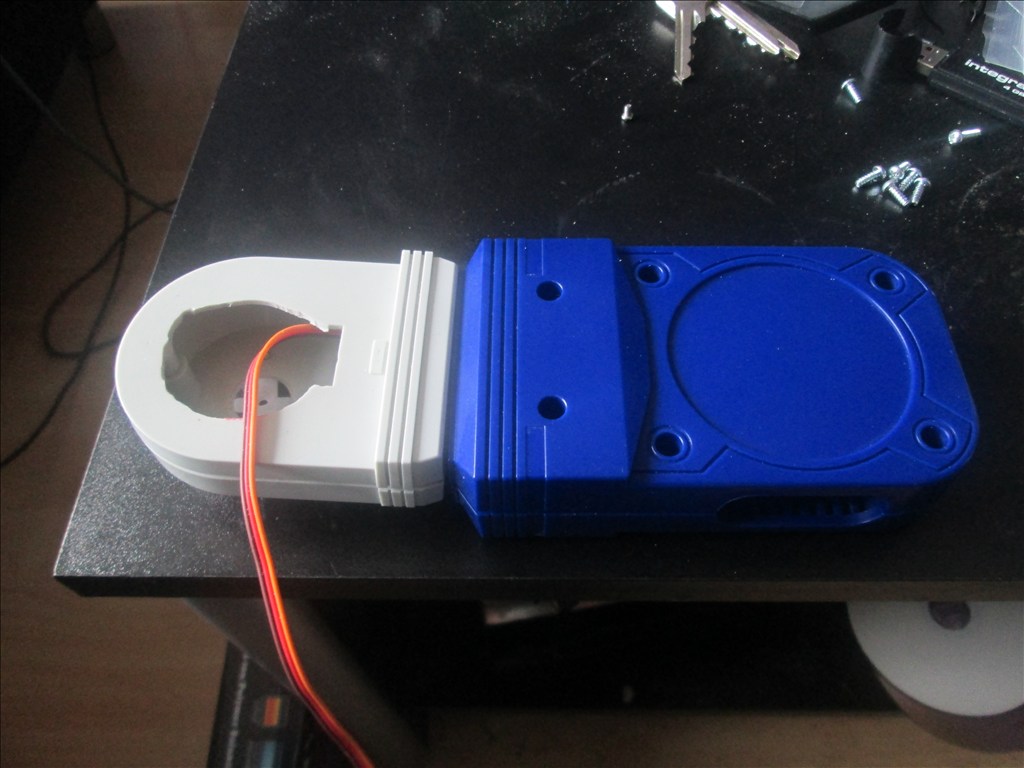
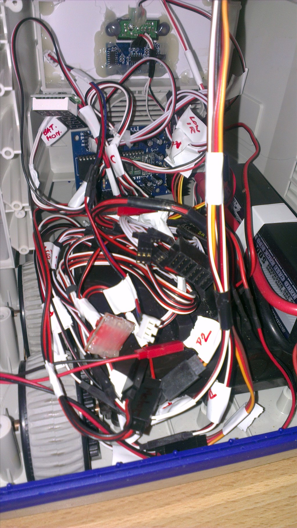
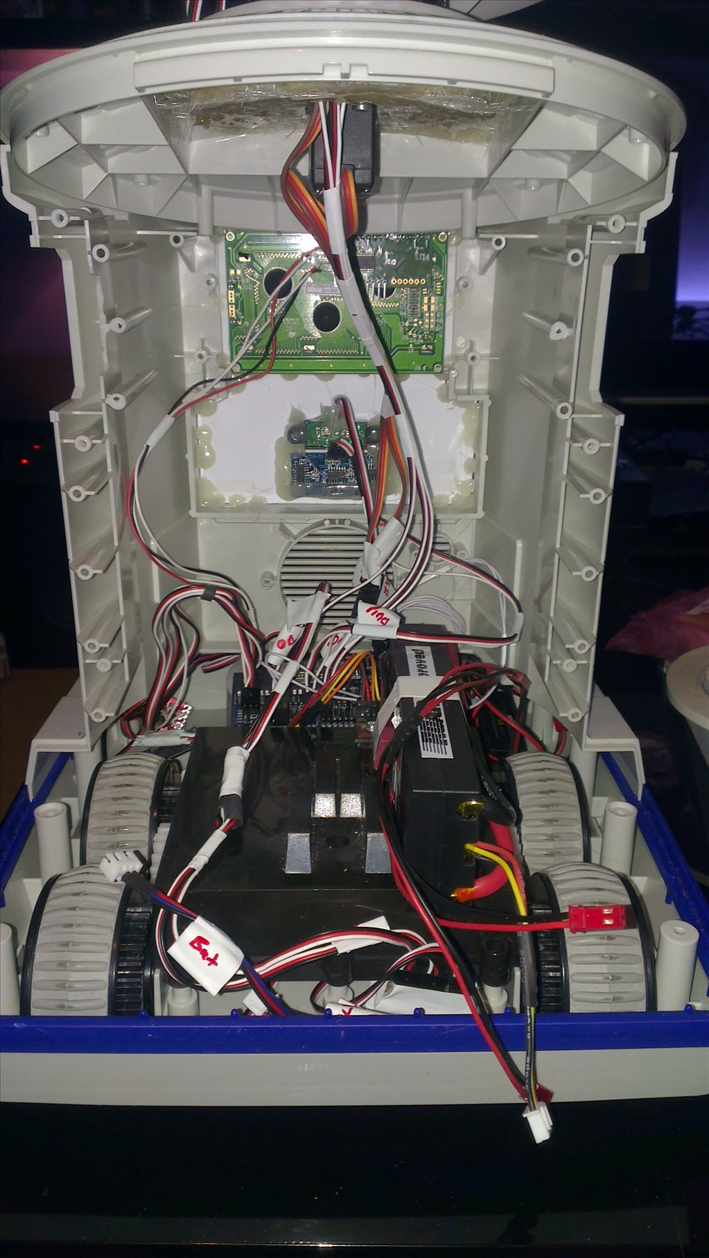
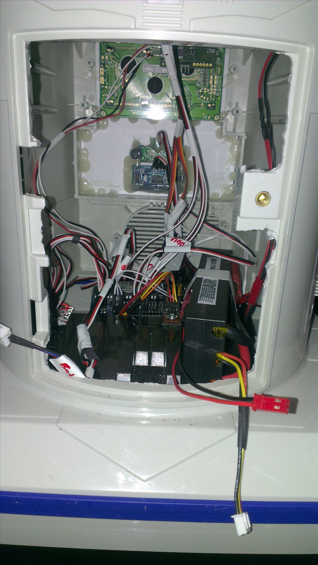
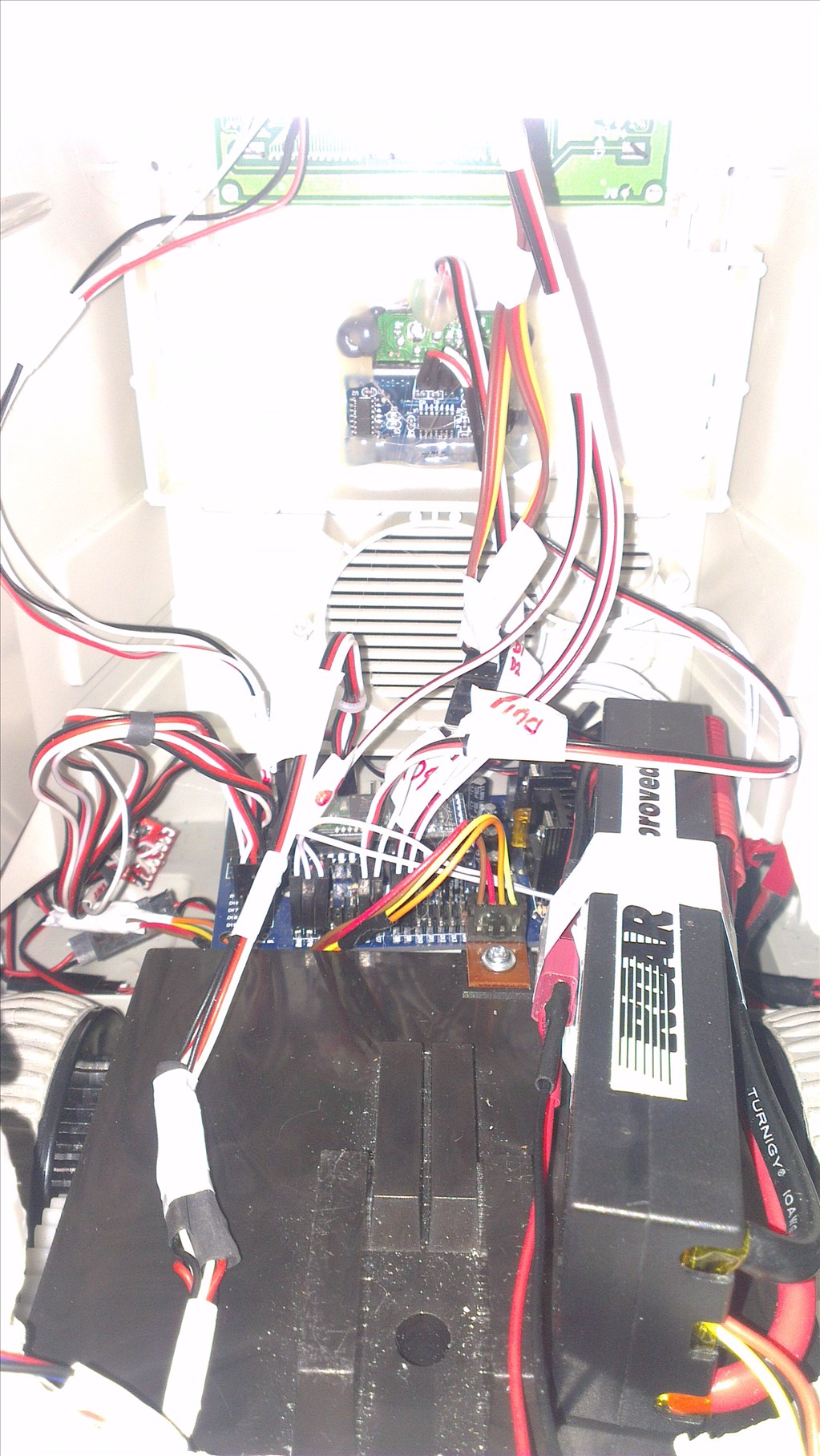
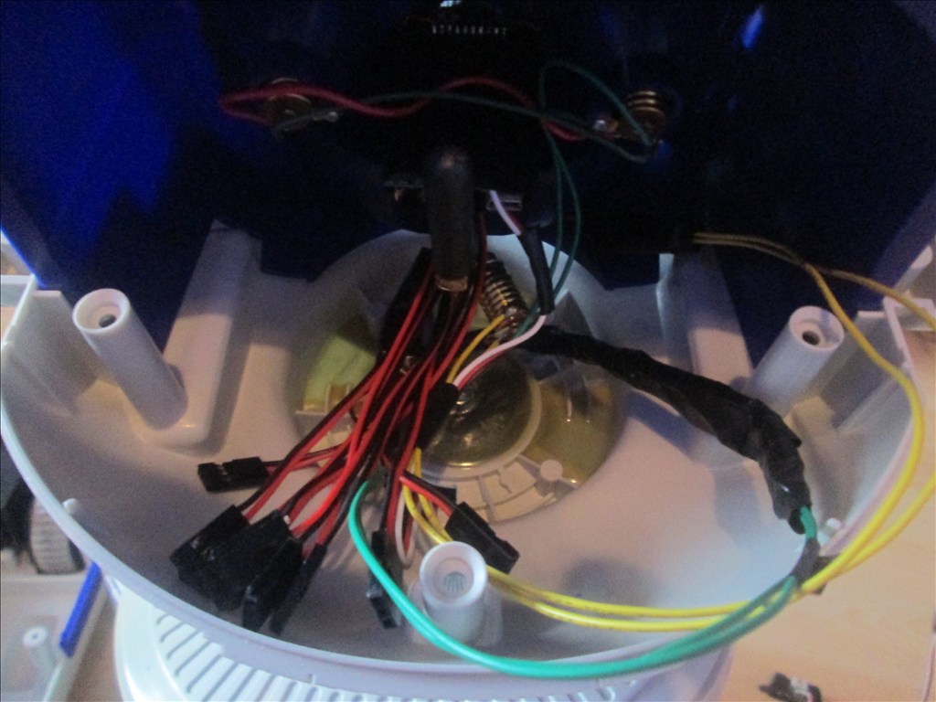
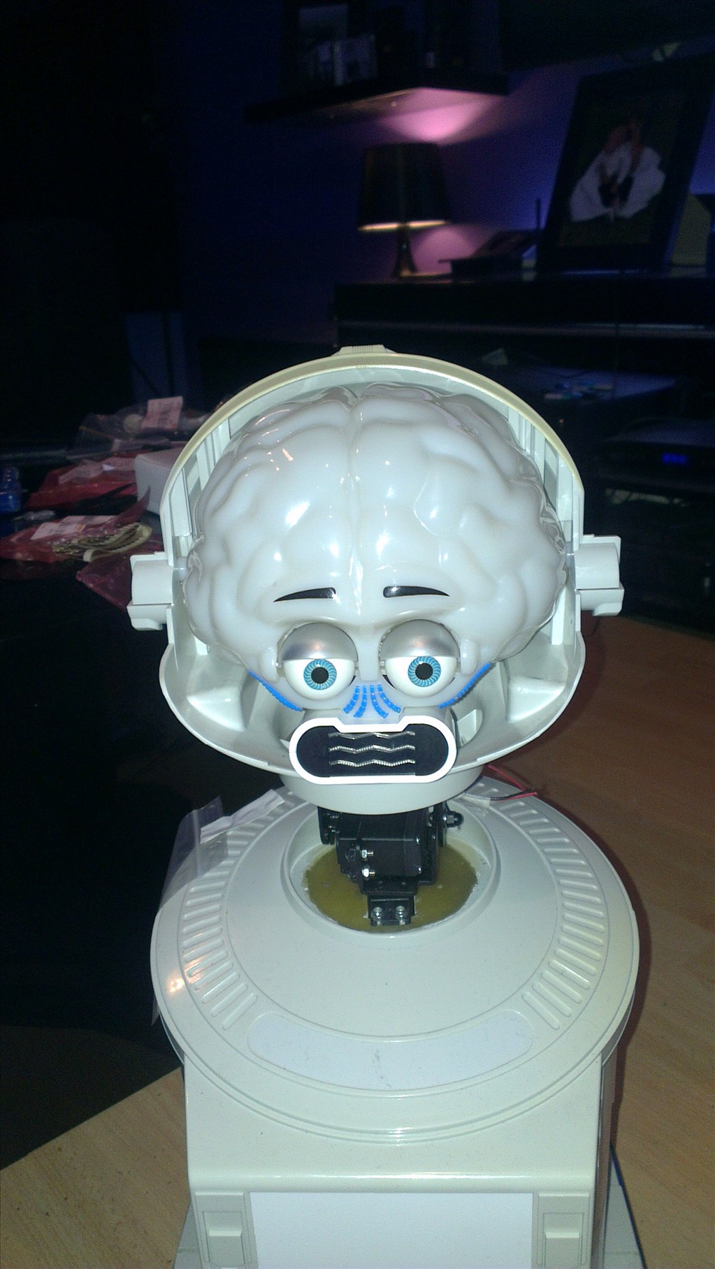
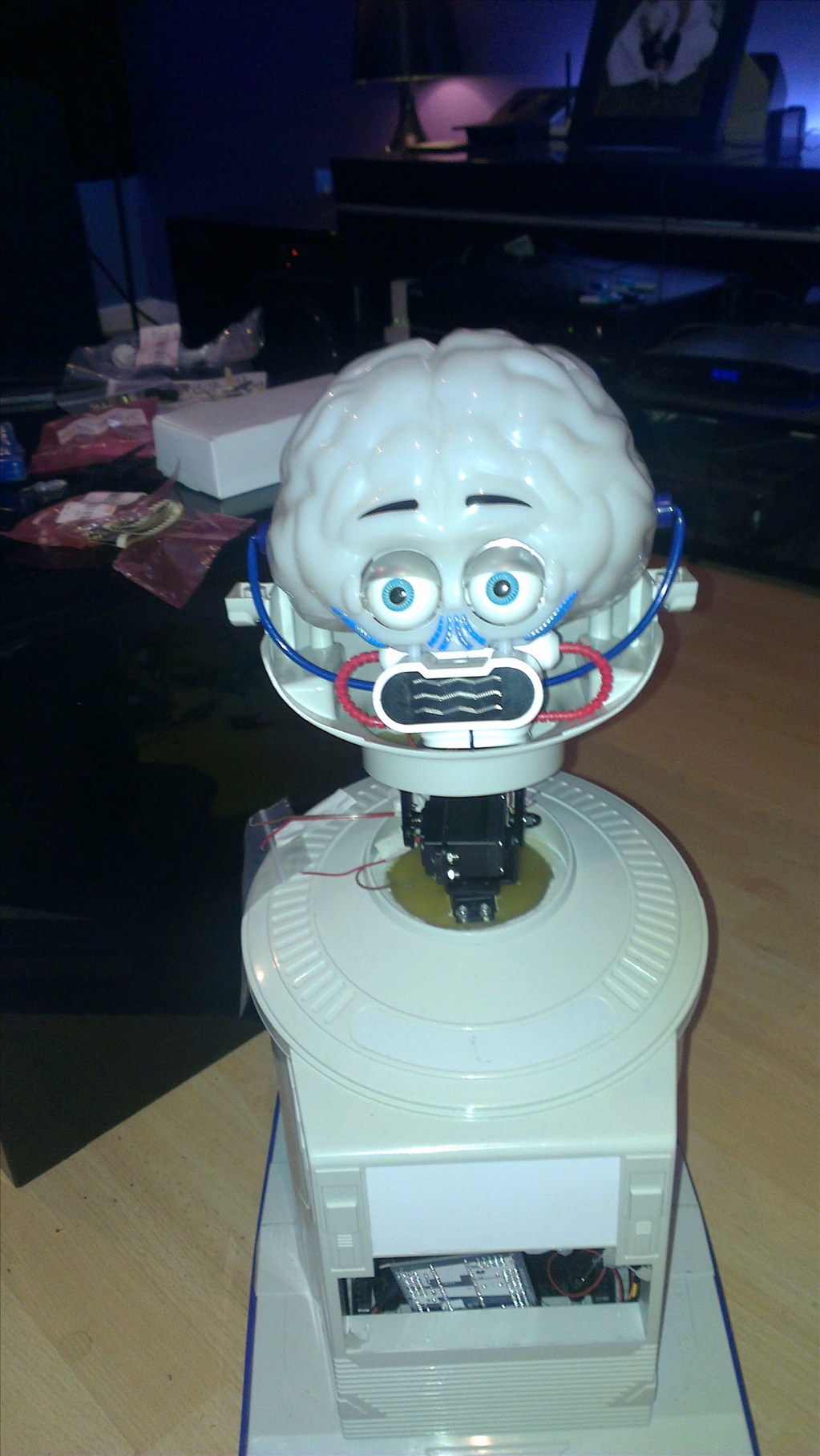
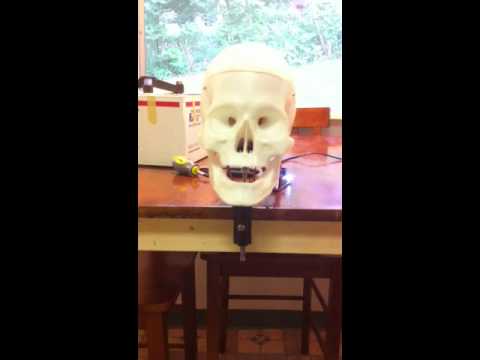
It wasn't long before this happened...
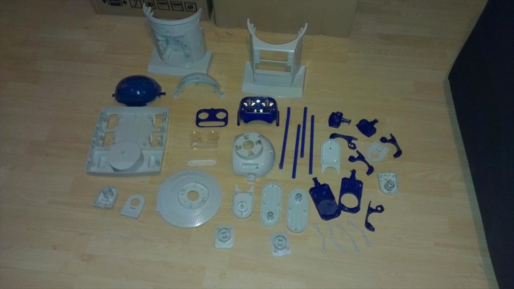
Now waiting to go in the dishwasher to get nice and clean.
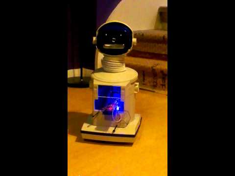
The plan is to make him autonomous, running 24/7 (except for when he knows to go charge himself up) but will also be adding in the various image tracking options.
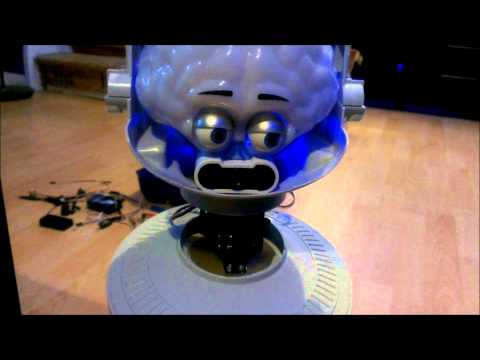
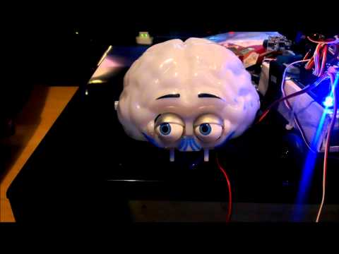
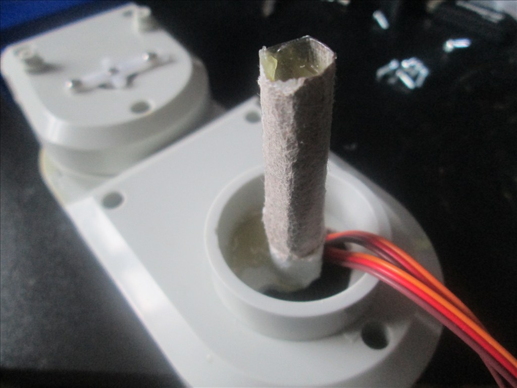
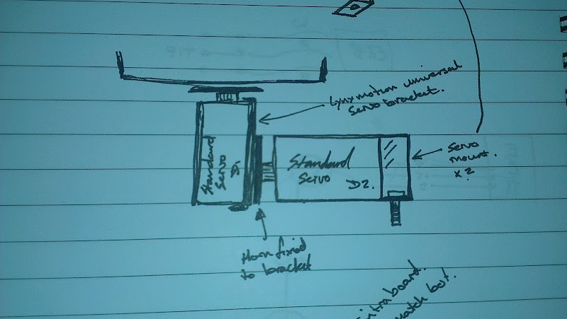
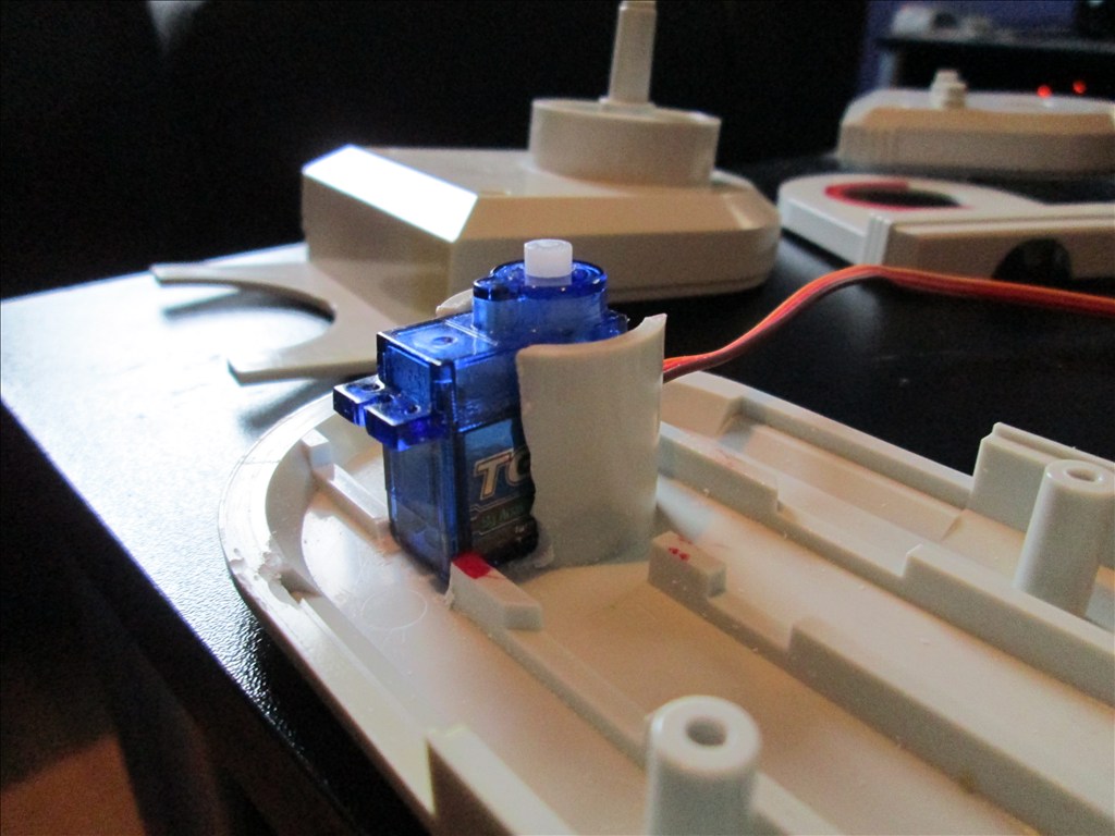
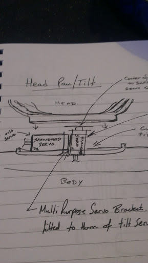
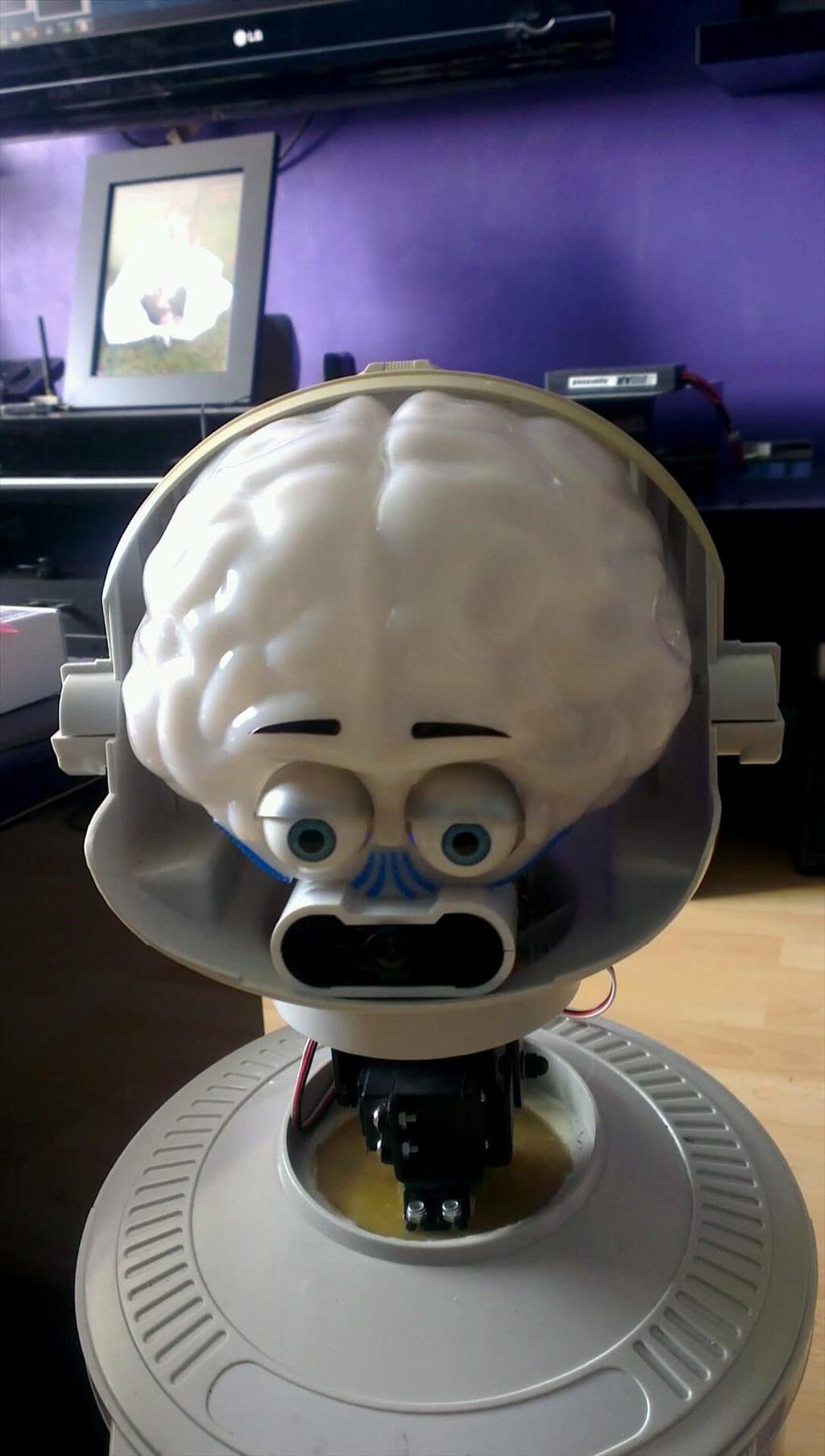
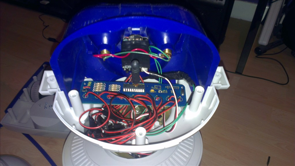
The only other slight modifications to be made to him are to convert the head to tilt & pan which will involve having to give him a small neck.
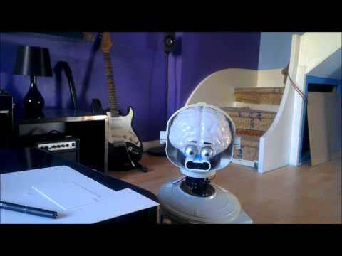
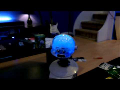
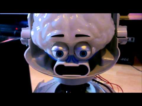
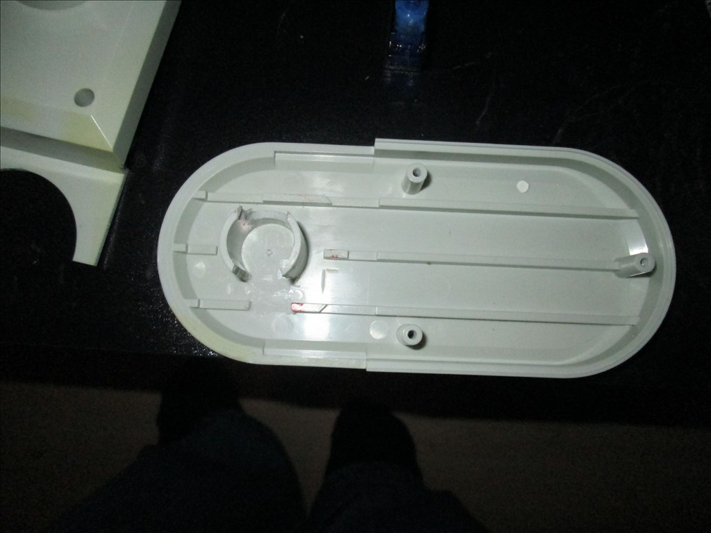
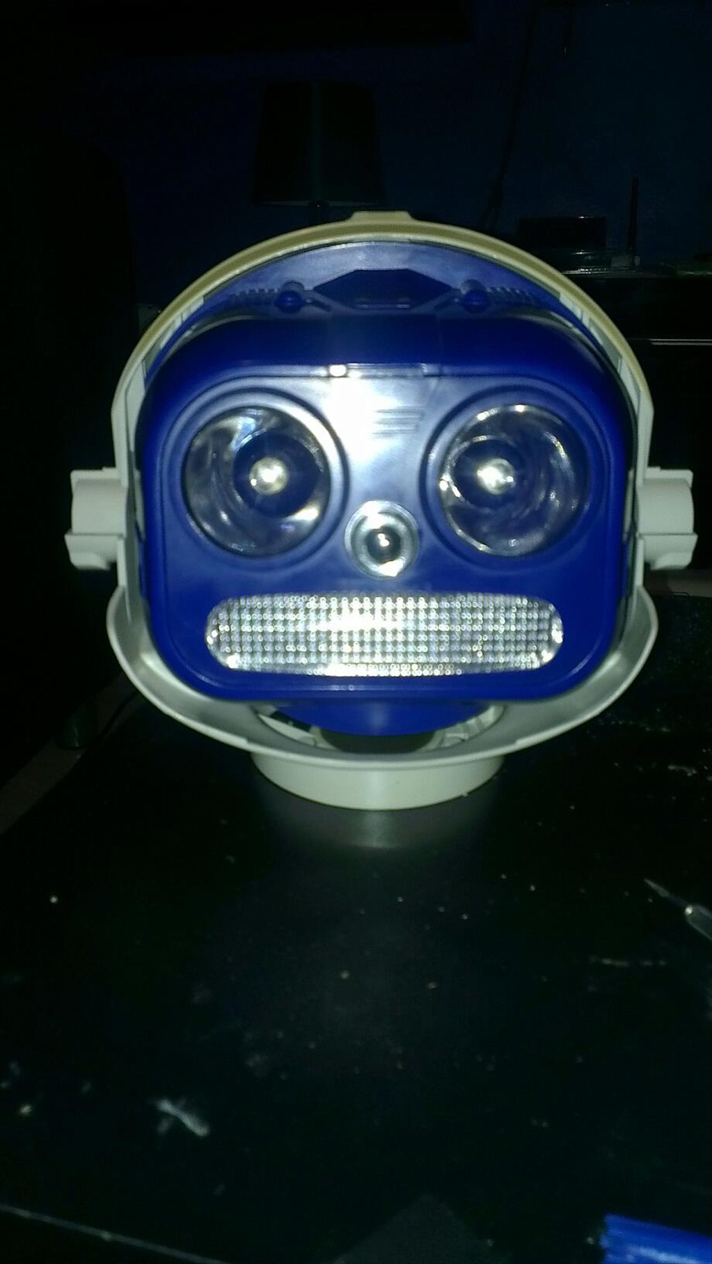
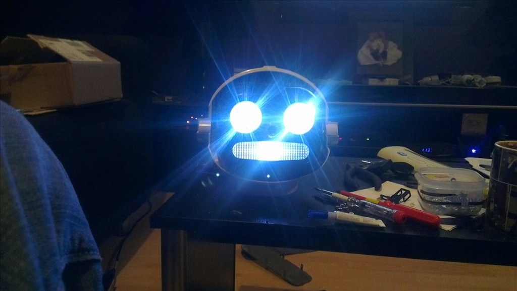
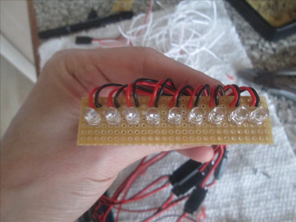
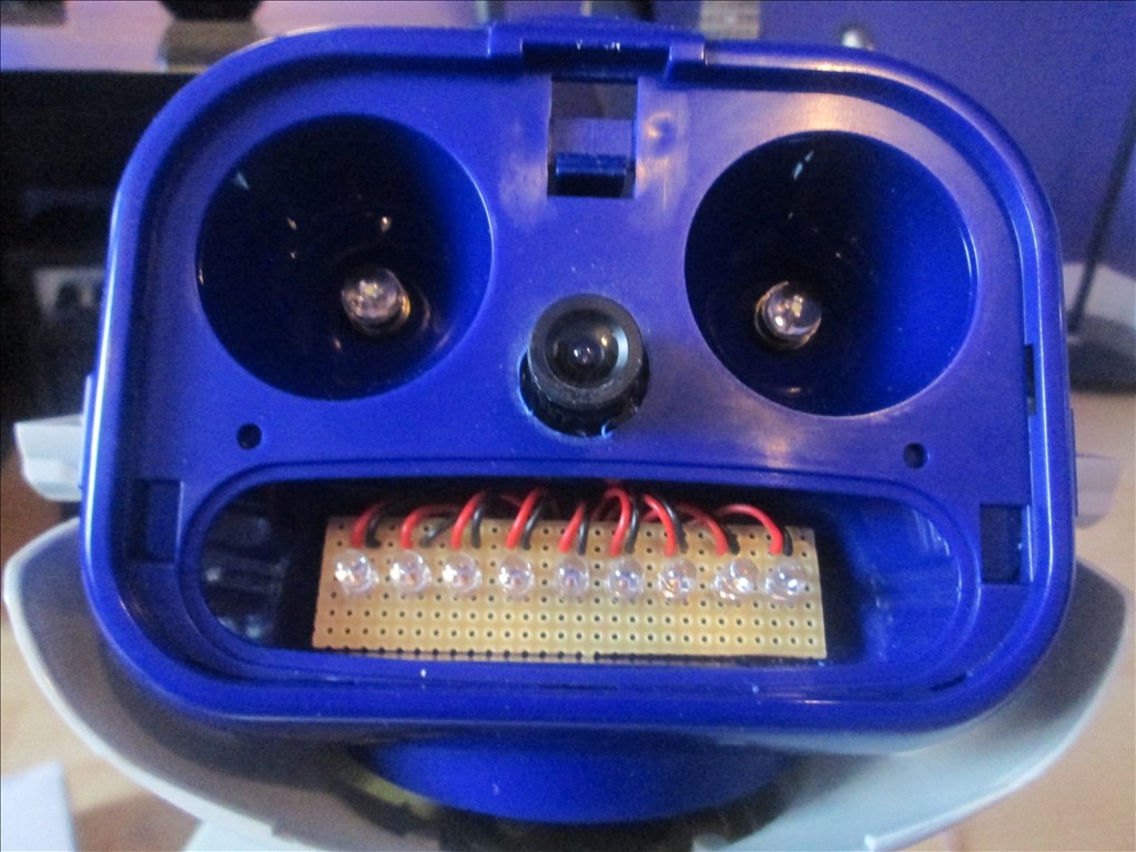
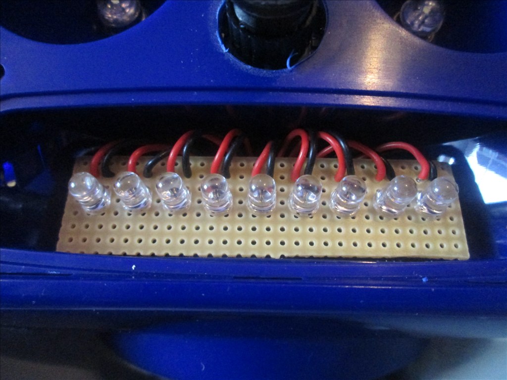
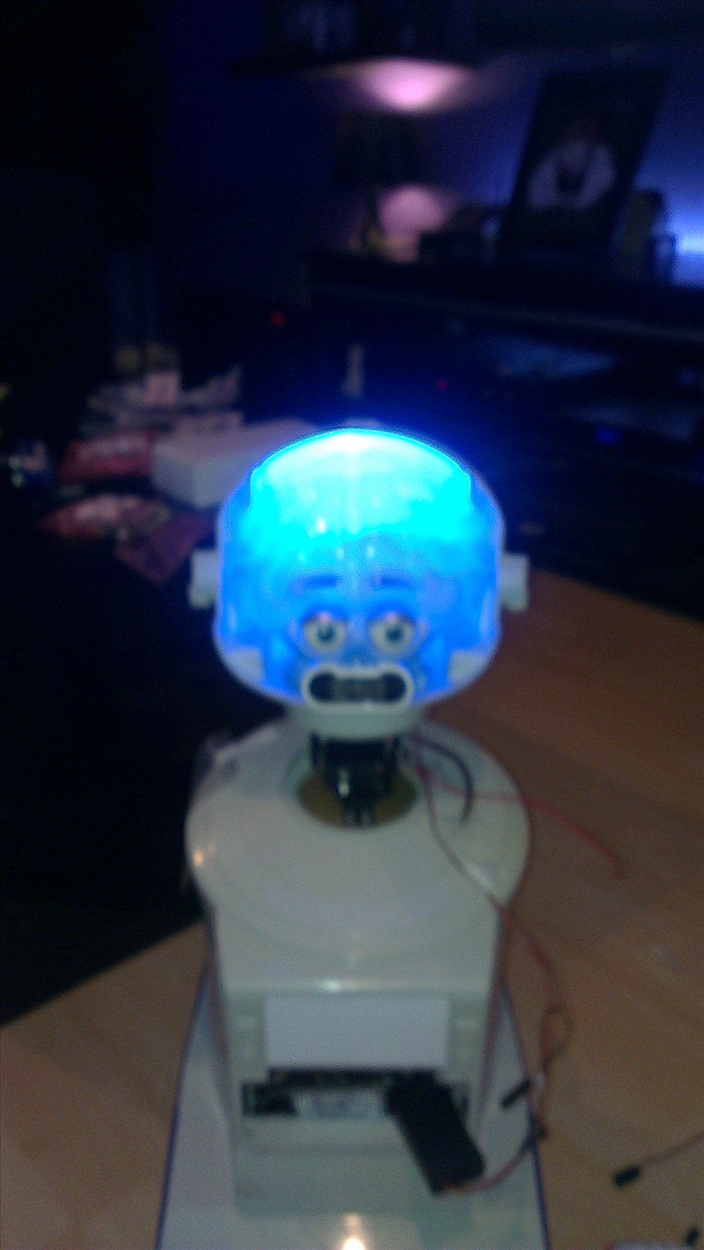
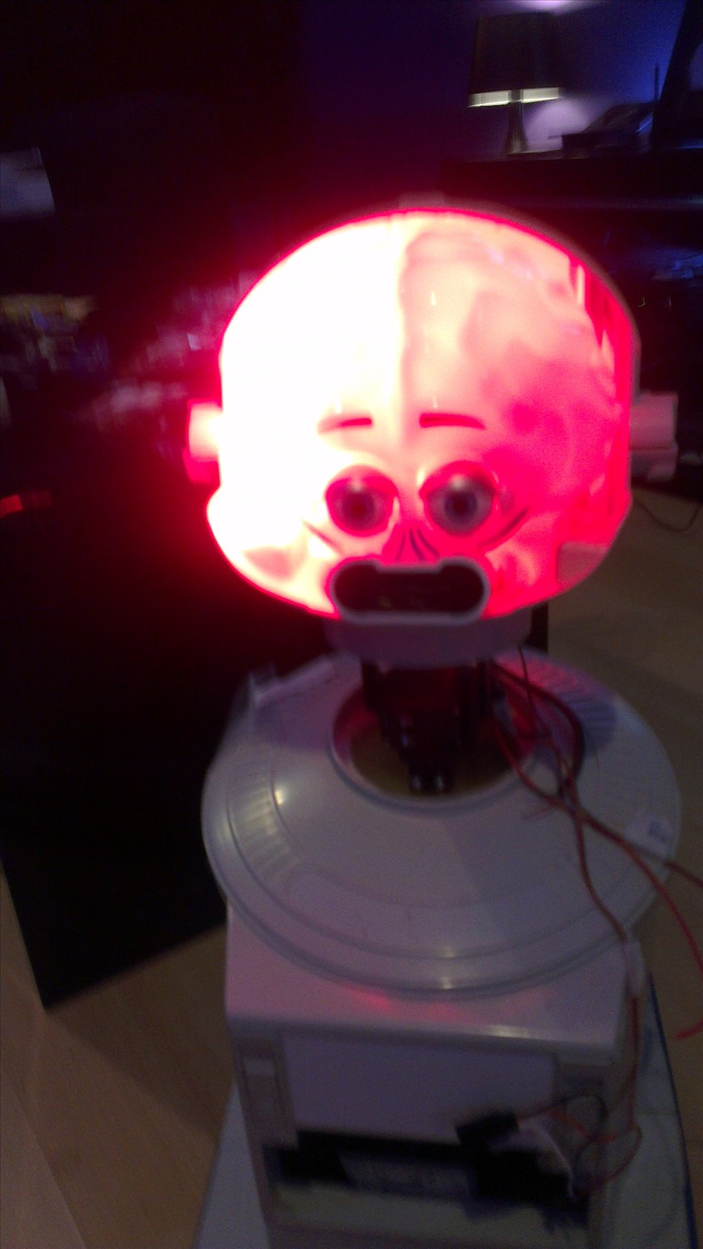
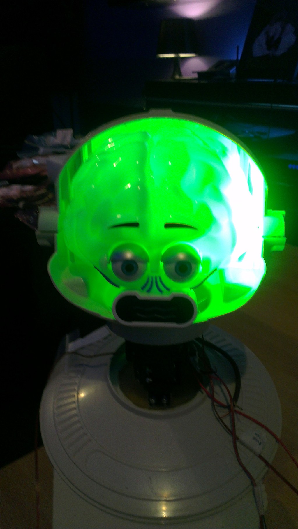
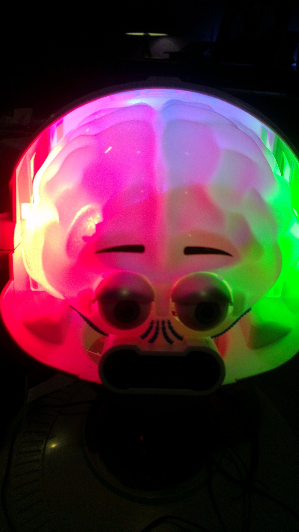
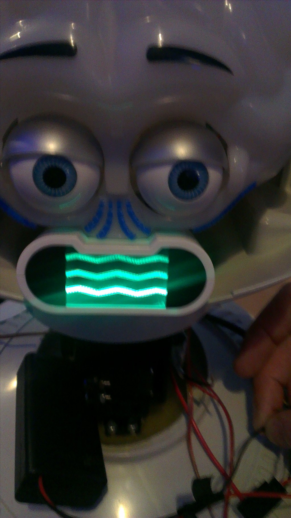
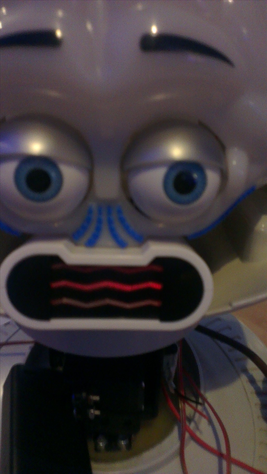
The head will include the camera. I haven't yet decided to fit it in one of his eyes or to make it his nose. The issue to overcome with this is the blue tint on the bubble head. The mouth will have a light or some lights in which flicker when he speaks.
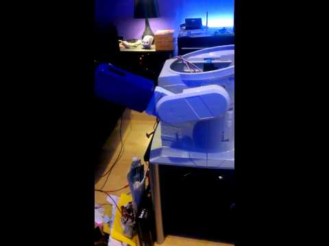
The arms will be given some life with servos at the shoulder joints and the elbows provided I can get them to fit in there nicely.
Ultrasonic sensor will be in his chest, probably on a servo to give a wider view.
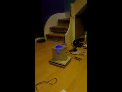
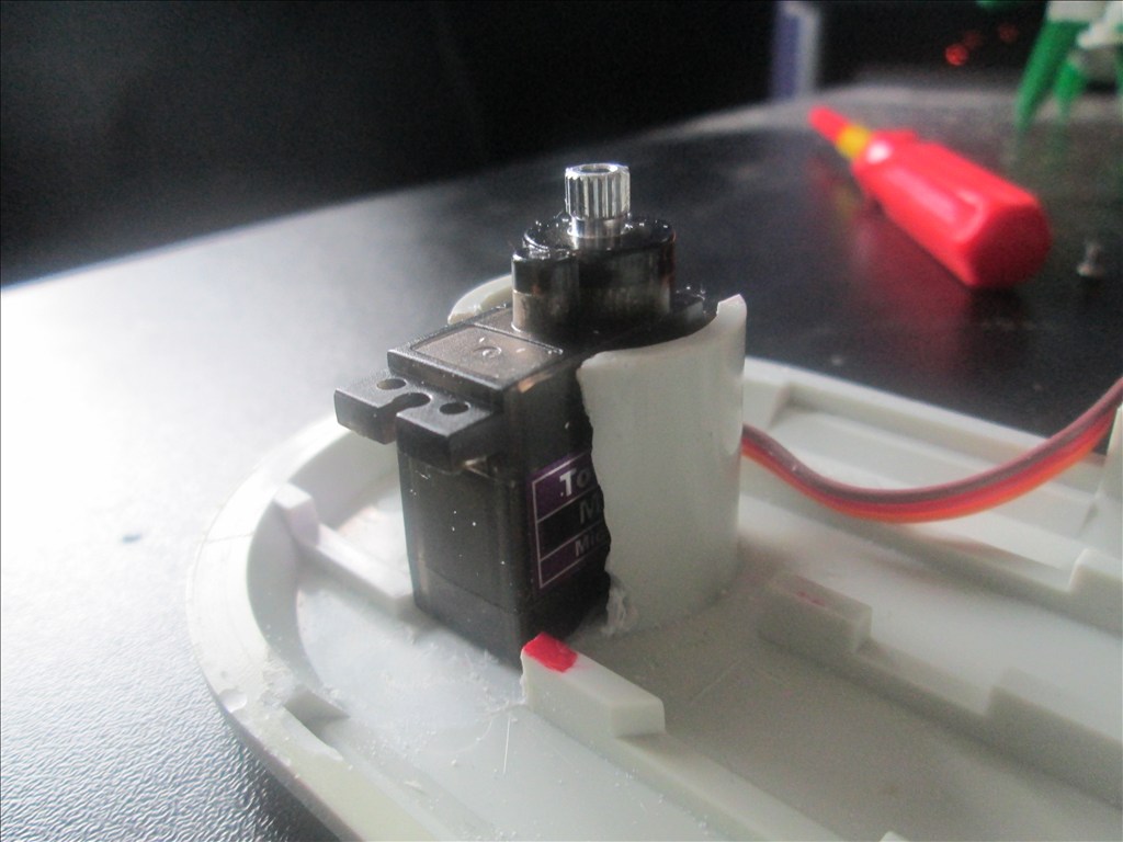
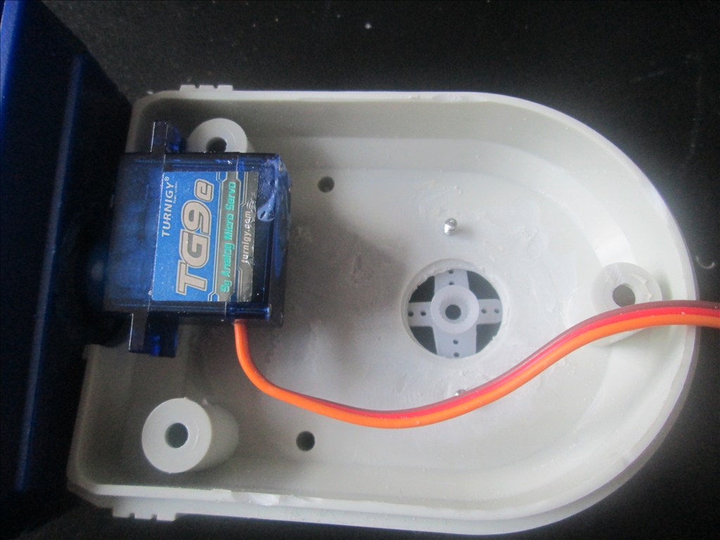
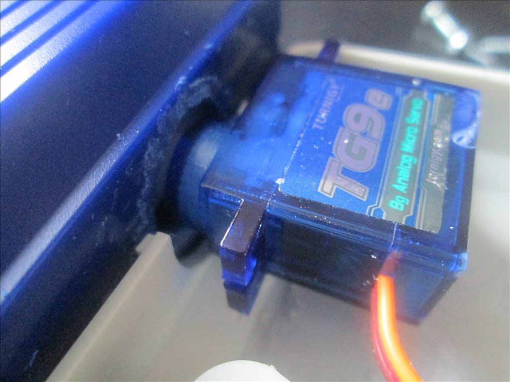
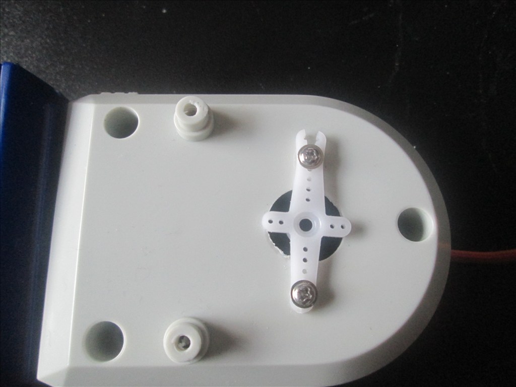
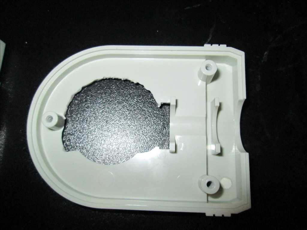
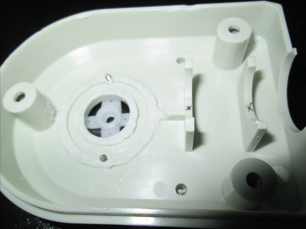
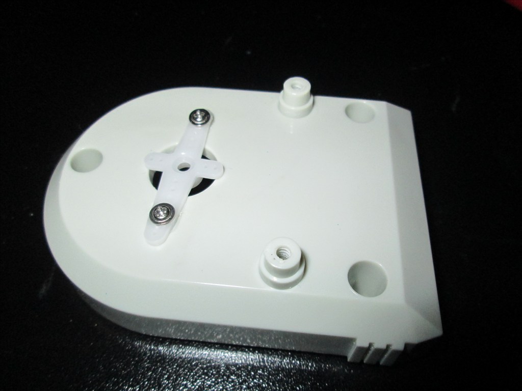
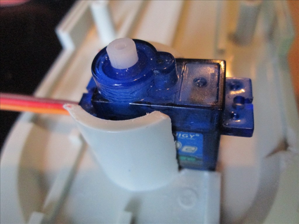
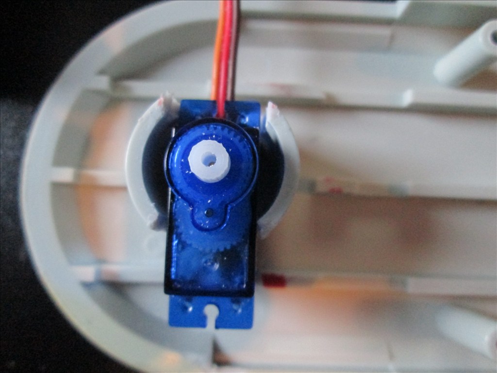
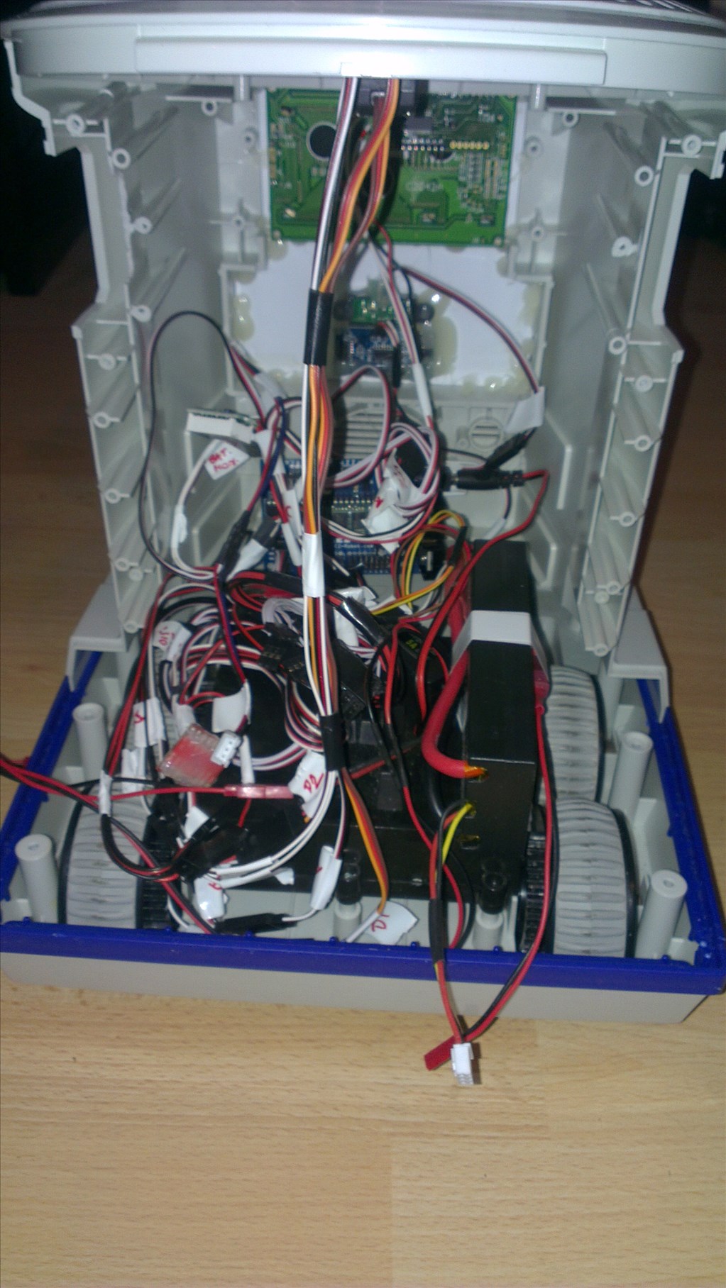
Original drive wheels and gearbox seem to be in very good shape so will plan to reuse those and just replace the existing motors for the modified servos if they can manage the task.
Speaker and microphone will be in the original positions - if it's not broke why fix it?
Not too big a project but enough to give me a test, help me learn and bring an old robot back to life.
Discover more robots

Peterfrisch's It's Yellow, It's Boxy, It's .... No Wall-E...
Markthebotbldr's R2D2 Interactive Hacked!

thats what i am too perfectionist too,everything has to be well tested ,one reason my projects take much longer then everyone else same in my hose ,my wall must be perfect condition and no GlYPHS or anyother making or stuff like beacon on my walls
LOOKS like RICH we have something both in common
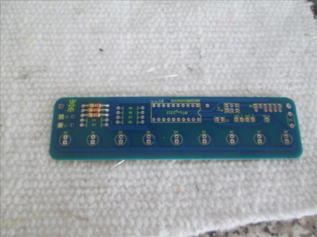
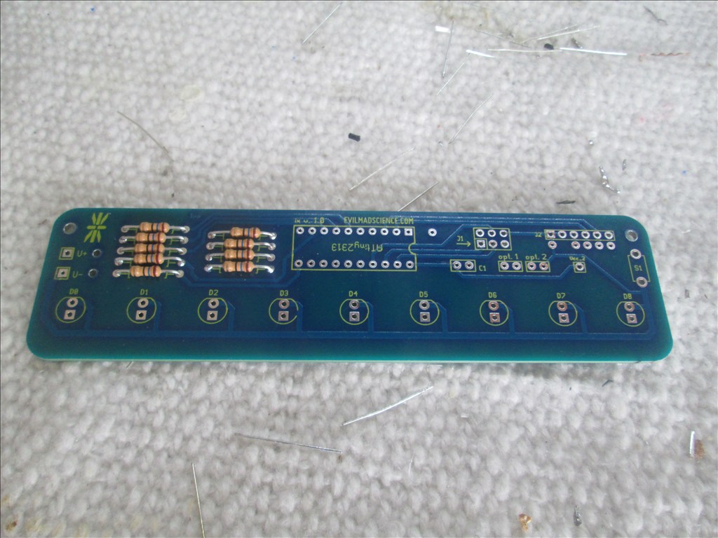
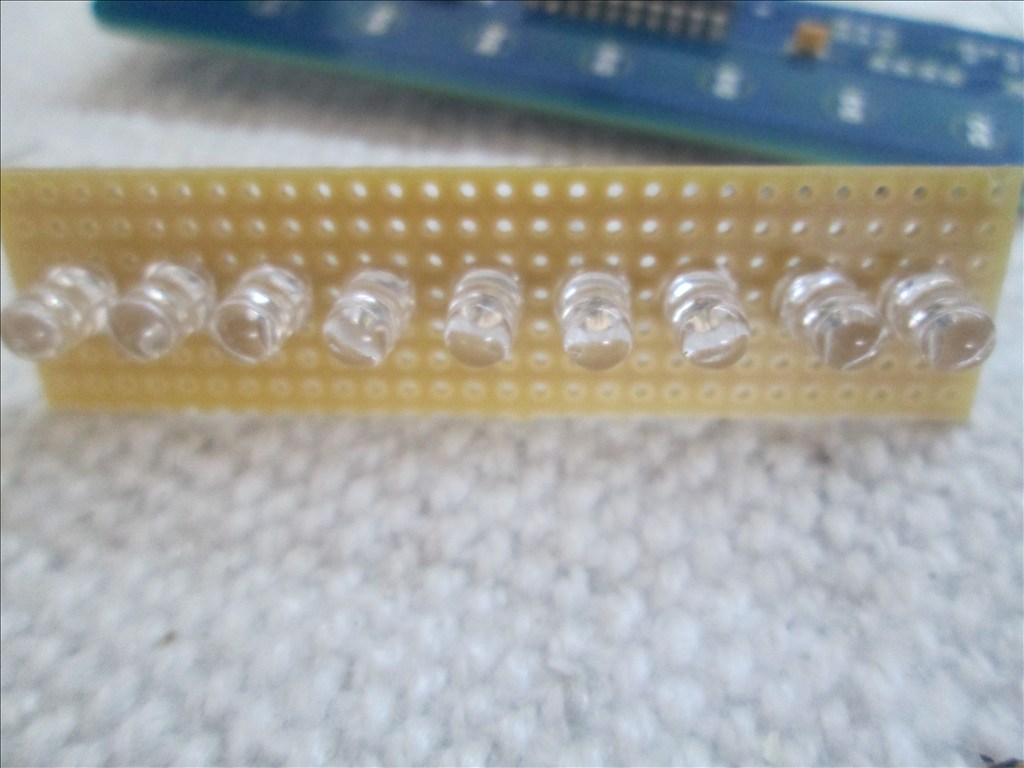
ON larson scanner it looks good i bought one for a test,but circuit is too simple ,i like making my own from scratch
hope to see more on the mouth design like the cover plate for the mouth
MOTHERS day in UK WOW,in usa its in may,anyway happy mothers day (not you rich) your mom we mostly take our mom out for a big dinner party,and she does no work for that day
Useless post removed
i though maybe you may make your own lens,no TALKING ROBOT
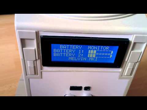
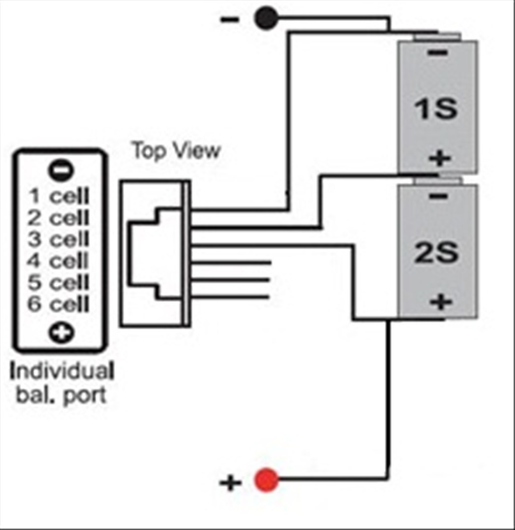
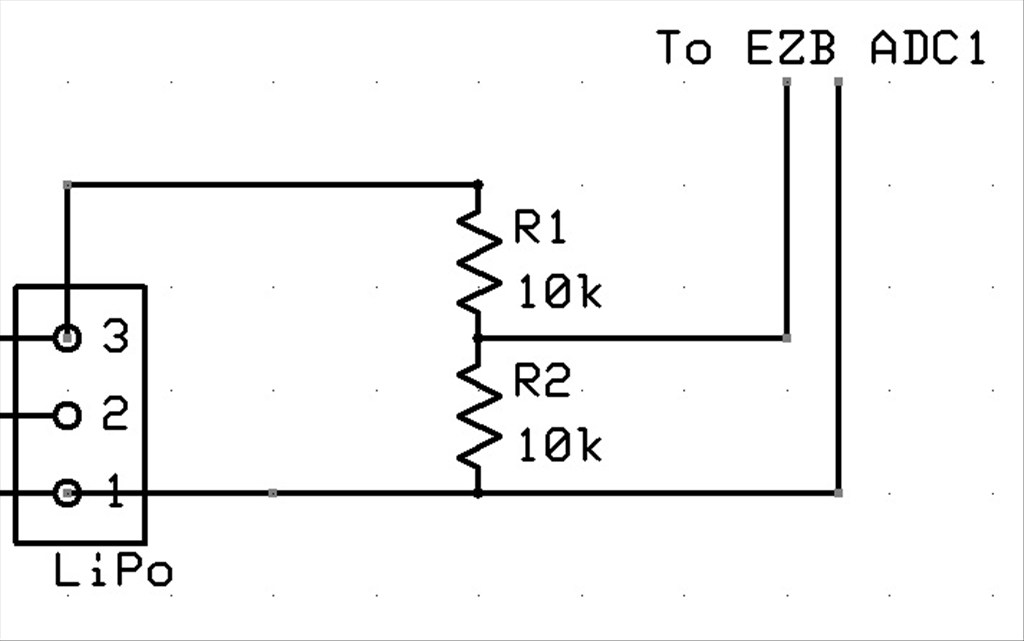
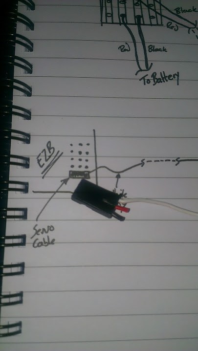
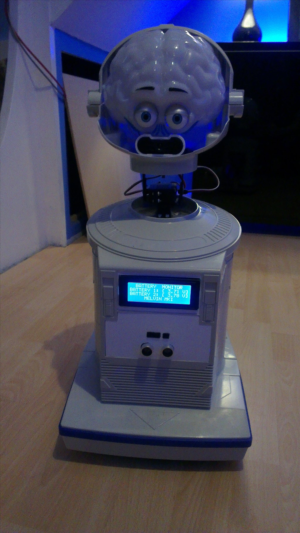
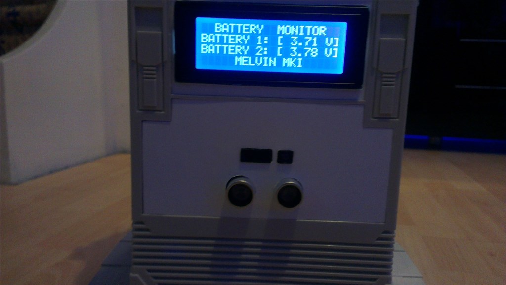
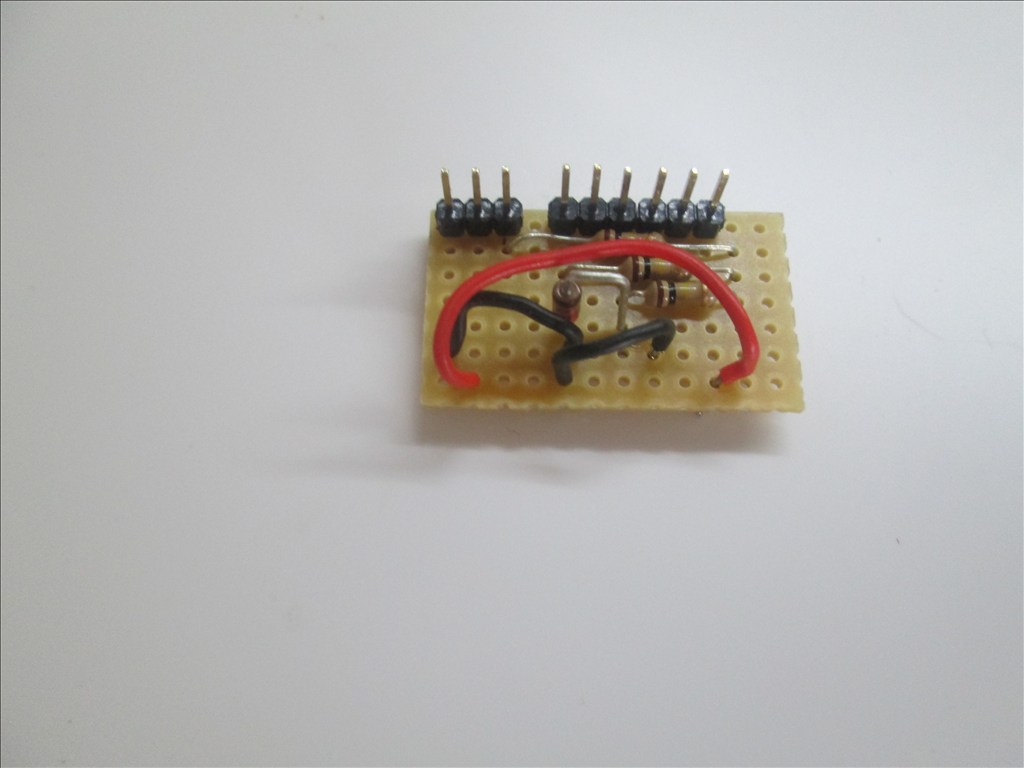
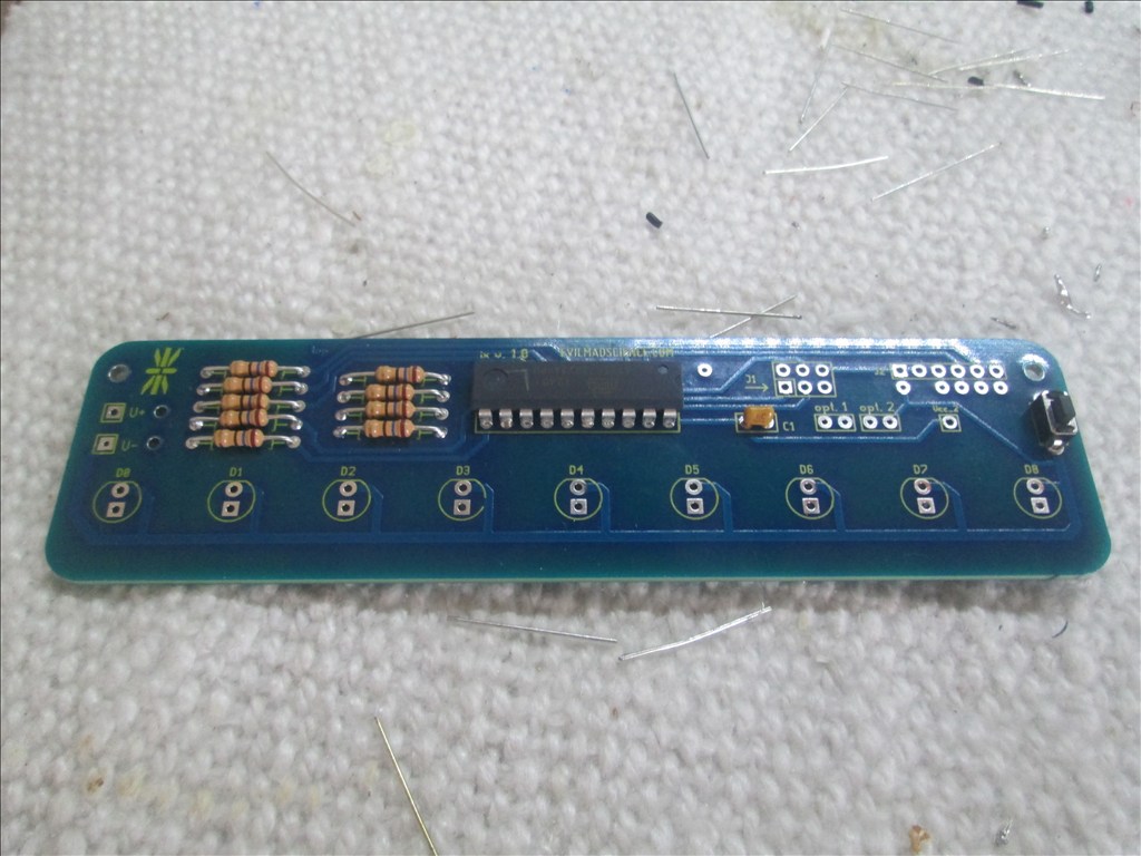
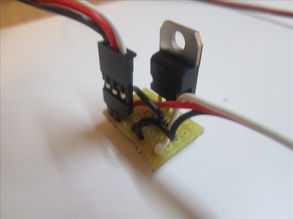
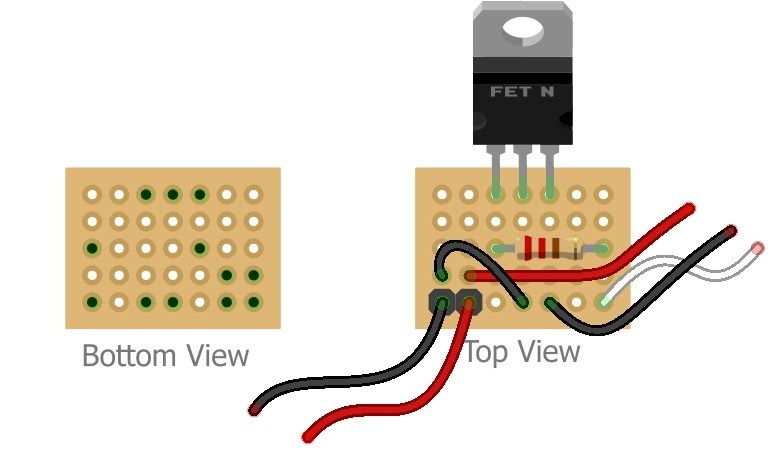
If my calculations are correct this should be at the top of page 27, so a perfect place for another detailed tutorial... the LiPo monitor
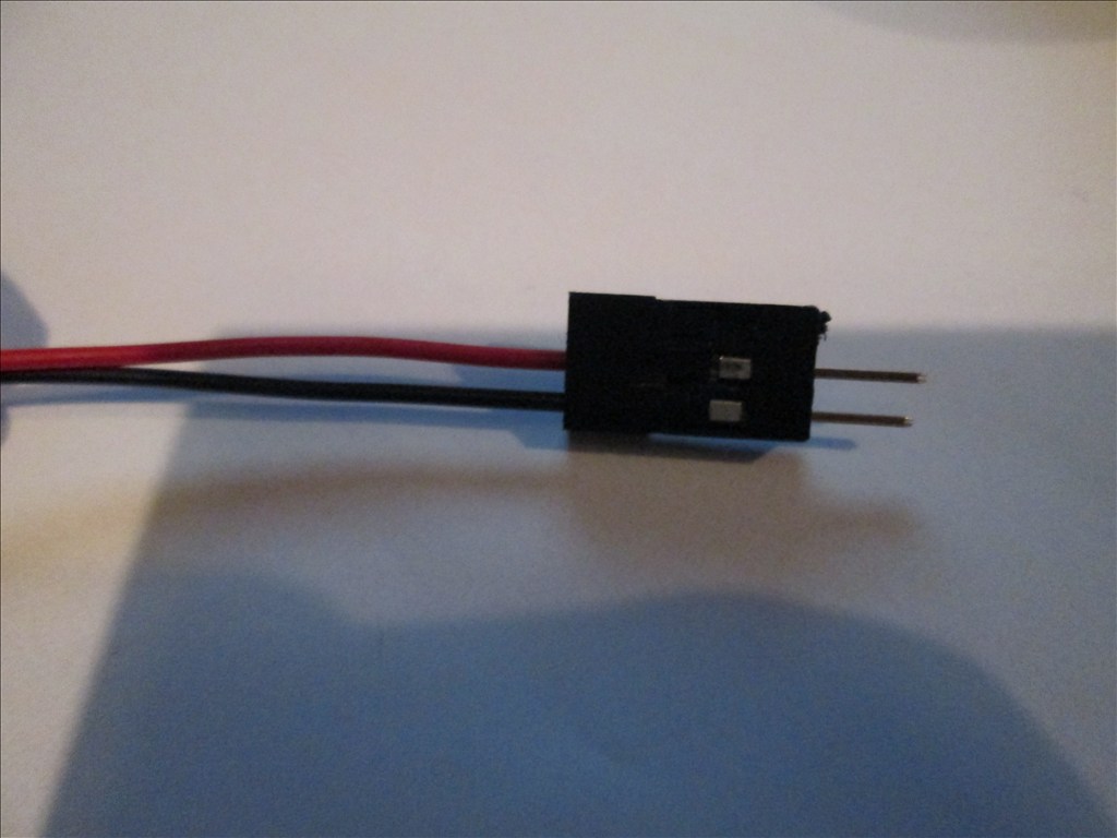
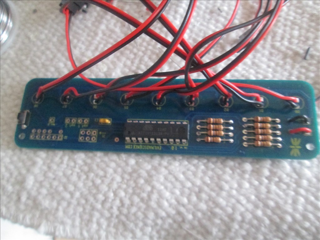
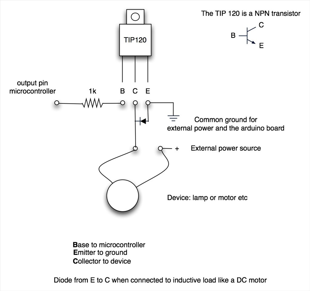
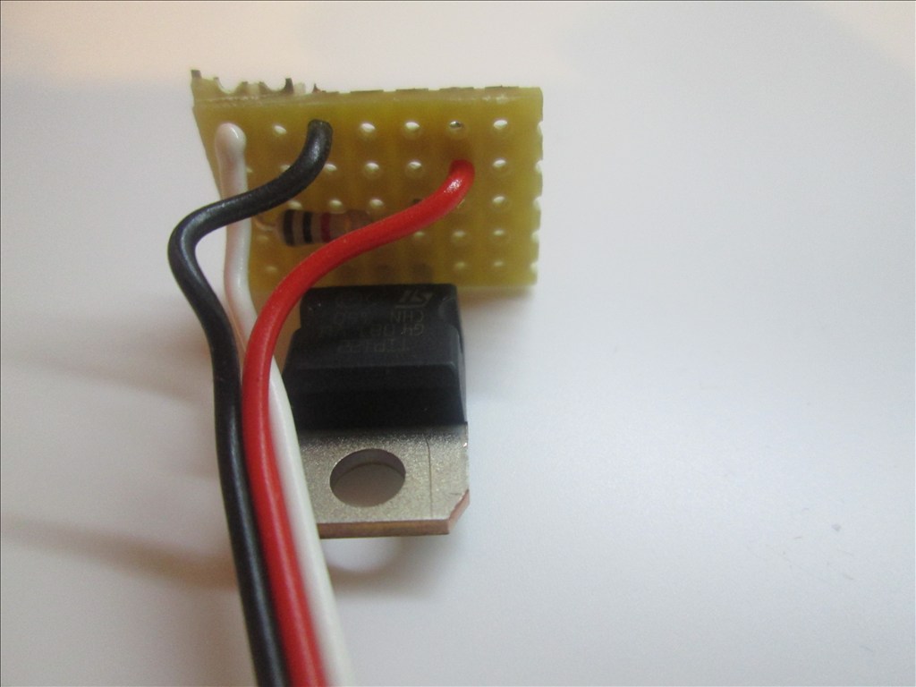
Parts needed: 1 x Zener Diode 5.1v 500mA (Farnell ref 1861447) 3 x 100k ohm Resistors (Farnell ref 9339078) 1 x Small Piece of Strip Board (12 strips x 7 rows) 3 x Pin Header (1x3) or 1 x Pin Header (1x3) and 1 x Pin Header (1x6) 1 x servo Extensions (male to male) Solder Soldering Iron Cutters
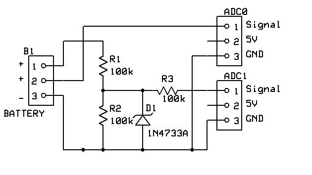
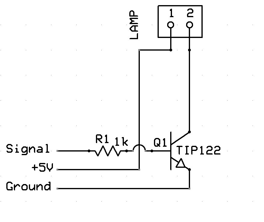
The Schematic:
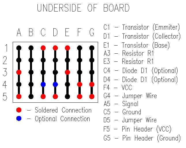
Method:
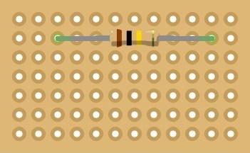
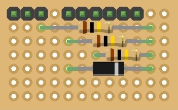
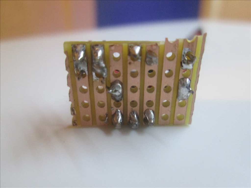
Solder R1 - 100k resistor from Row 2 Column 3 to Row 2 Column 11
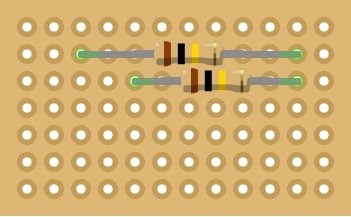
Solder R2 - 100k resistor from Row 3 Column 5 to Row 3 Column 11
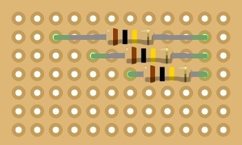
Solder R2 - 100k resistor from Row 4 Column 7 to Row 4 Column 11
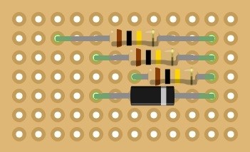
Solder D1 - Zener Diode from Row 5 Column 5 to Row 5 Column 11 (Band to the right)
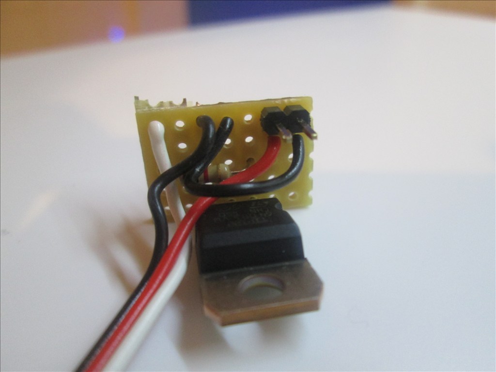
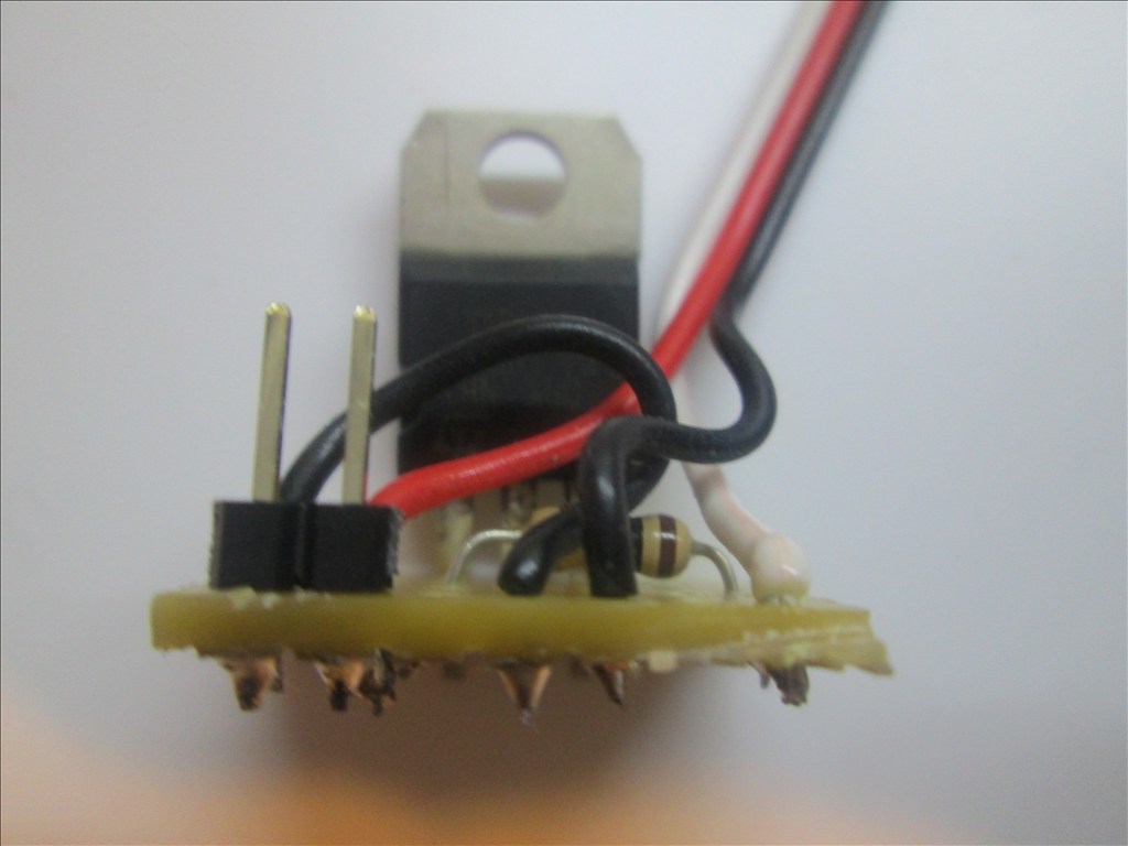
Solder the pin headers on Row 1 Columns 1, 2, 3, 5, 6, 7, 8, 9 & 10
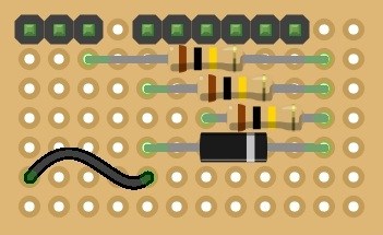
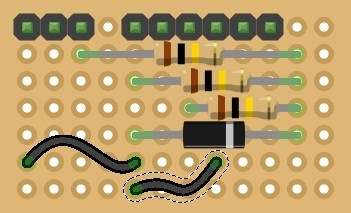
Solder some black off cuts of wire from Row 6 Column 1 to Row 6 Column 5 and from Row 7 Column 5 to Row 6 Column 8
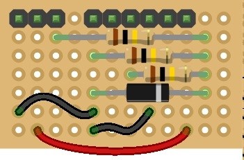
Solder an off cut of red wire from Row 7 Column 2 to Row 7 Column 10
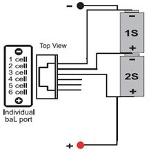
You're all done. Plug the balance port connector in to the 3 pin header on Row 1 Columns 1 to 3 (Ground to the left) and plug in some servo extensions (male to male) or 3 pin JST to servo on the two other headers (Ground on left on both), connect the other ends to ADC0 and ADC1 (or any other two ports if those are taken but you will need to adjust the script below if you do).
Now, to use the information in ARC...
The EZ Script
Note: The should be just a normal closed bracket ) but the forums tend to think otherwise.
EZ-Cloud Download
You should copy n paste this separately in its own thread and label it as a tutorial rich.
I will when it's done, it's not complete enough for that yet though
Thanks for this work Rich. We're lucky to have you on this forum.
I know They should commission a marble statue of me at EZ-Robot HQ lol. But seriously, it means a lot to hear that.
I'm glad to be able to contribute. If it helps one person then that's great, if it helps more then even better