


Now I have the EZ-B kit and the Hearoid it's time to start my Showcase thread.
I still haven't decided on a name for him yet, all suggestions are welcome.
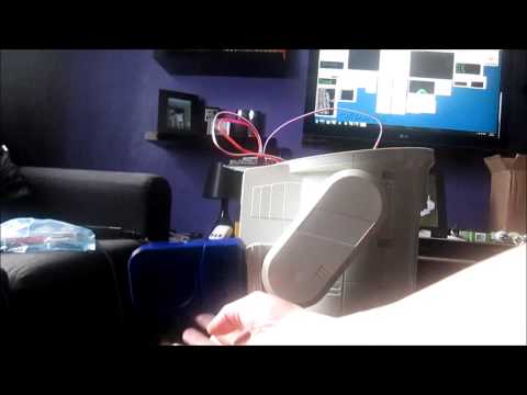
I won this robot on ebay weeks ago, for the past 2 weeks he has been waiting for me to collect him...
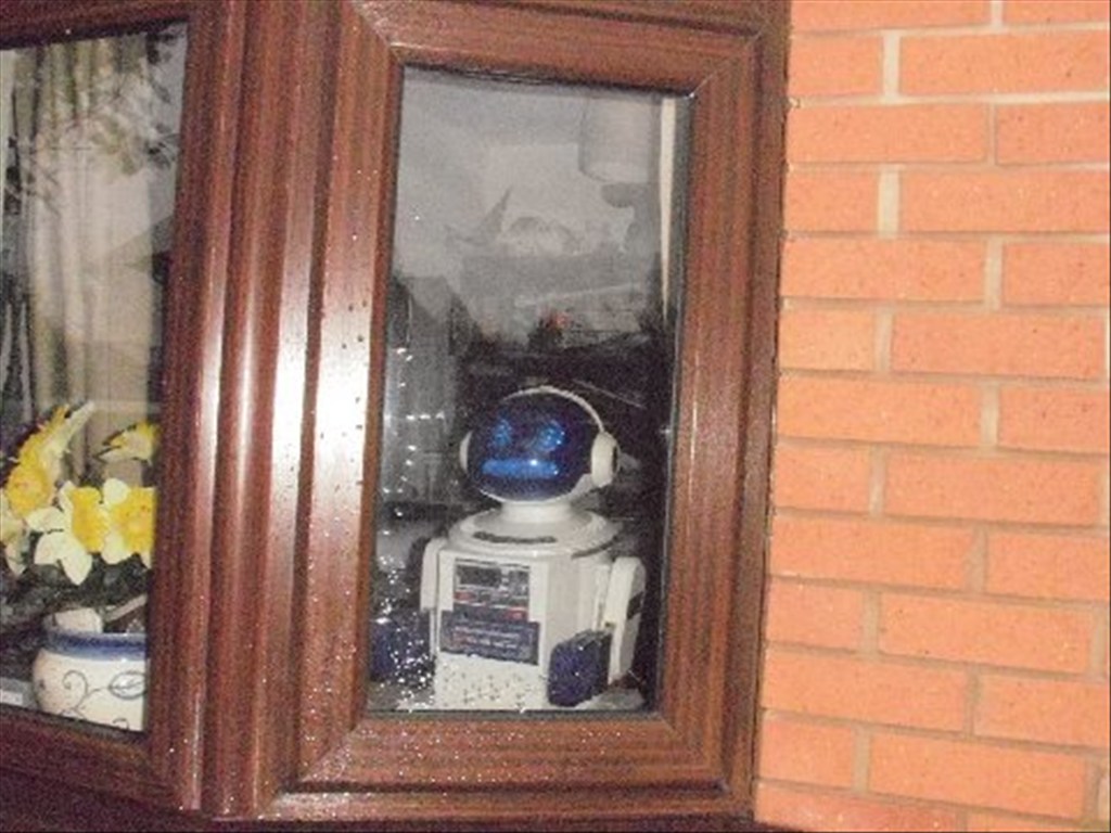
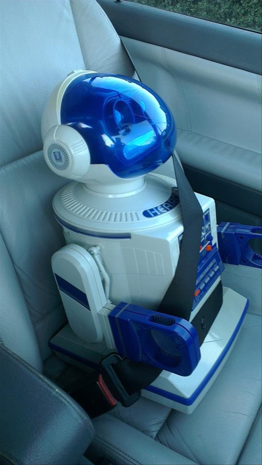
Today was the day, a road trip to pick him up and bring him back to his new home...
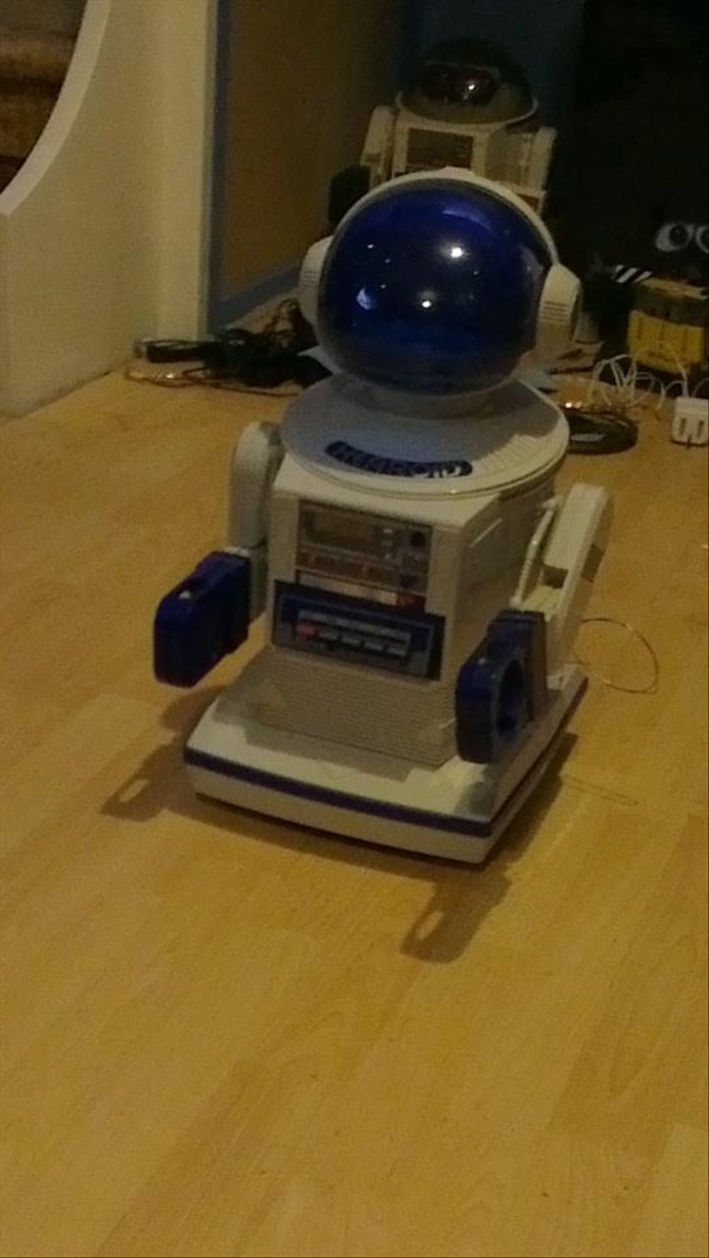
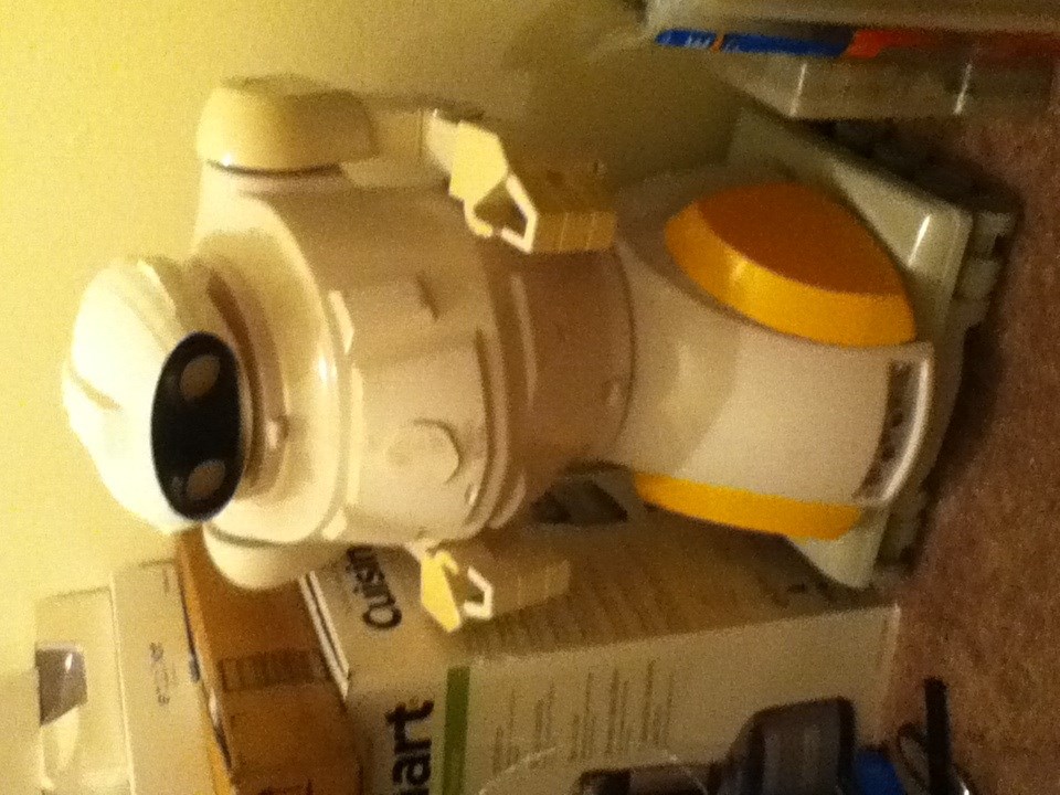
In his new home (with Omnibot and Wall-e in the background totally unaware they are next in line to be opened up)
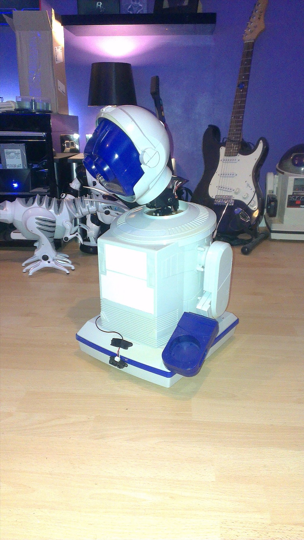
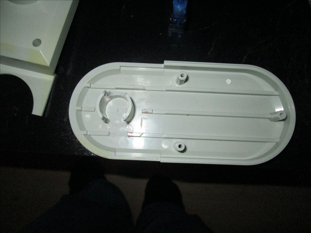
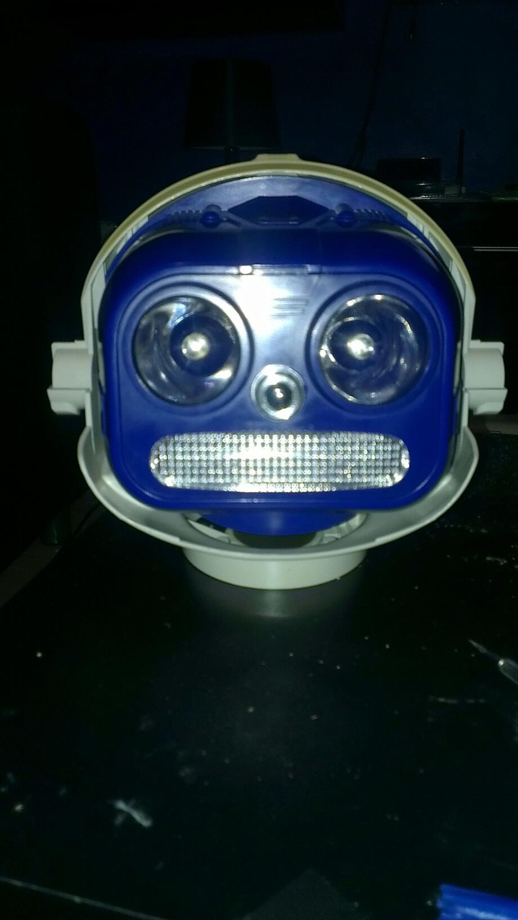
It wasn't long before this happened...
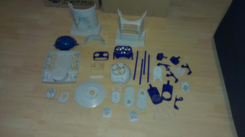
Now waiting to go in the dishwasher to get nice and clean.
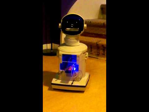
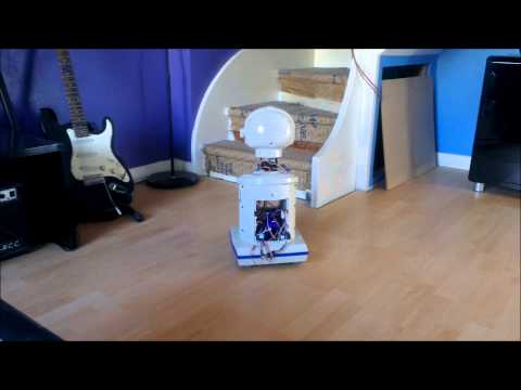
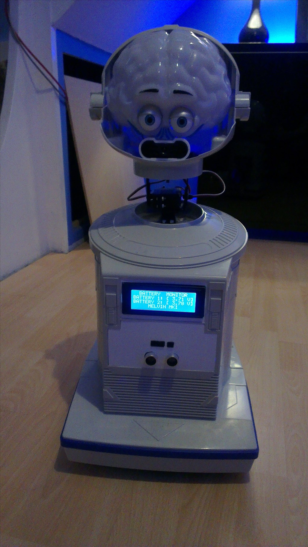
The plan is to make him autonomous, running 24/7 (except for when he knows to go charge himself up) but will also be adding in the various image tracking options.
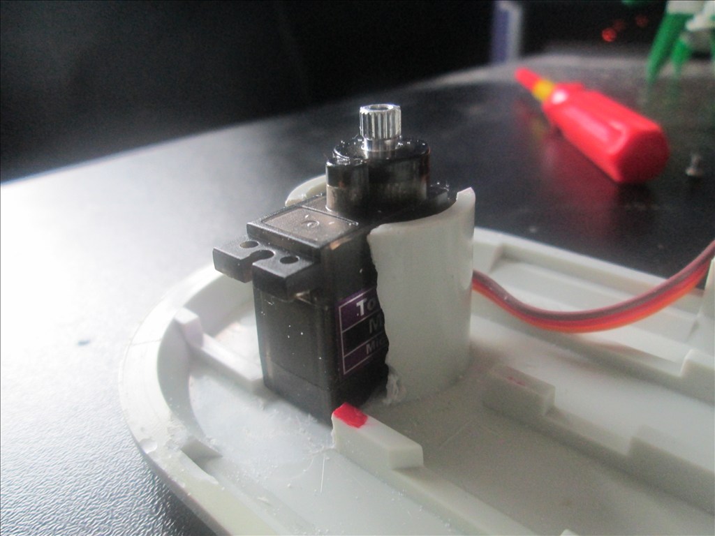
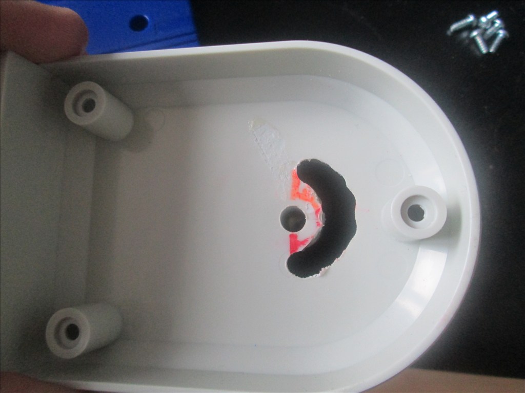
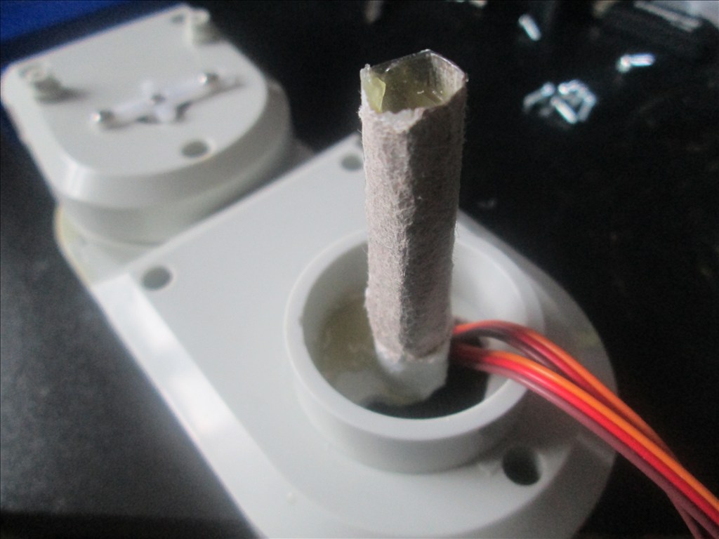
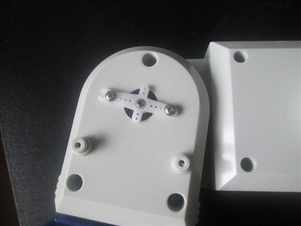
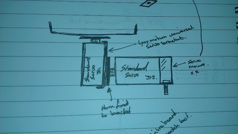
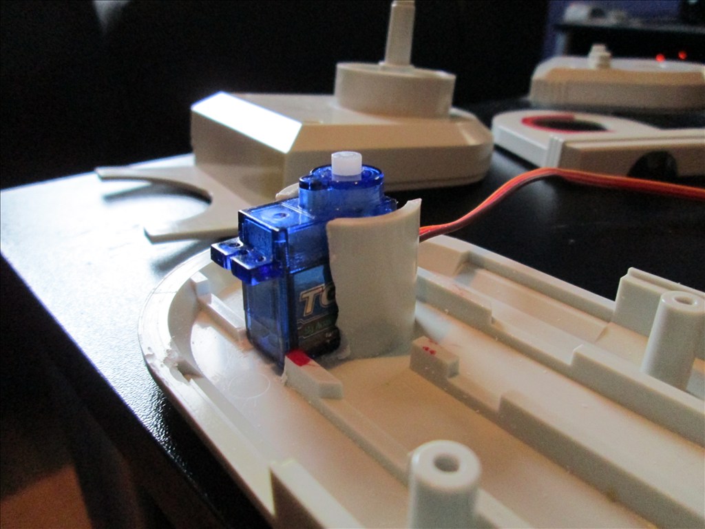
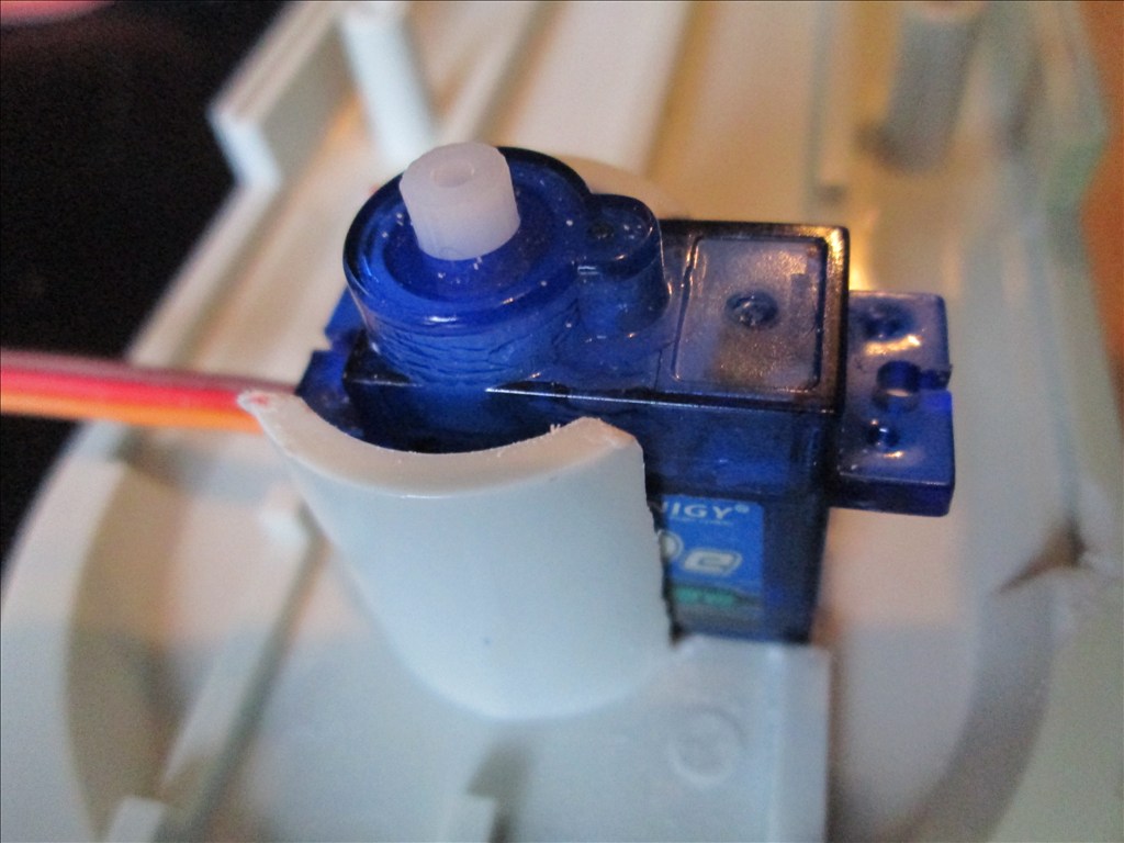
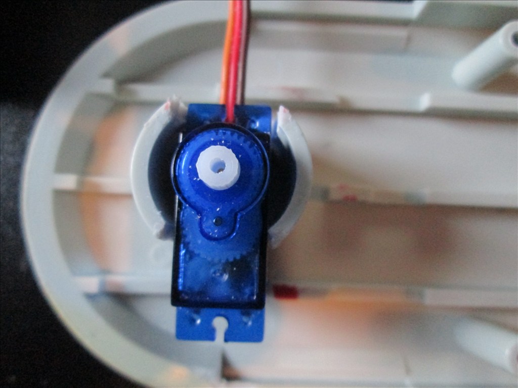
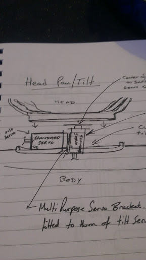
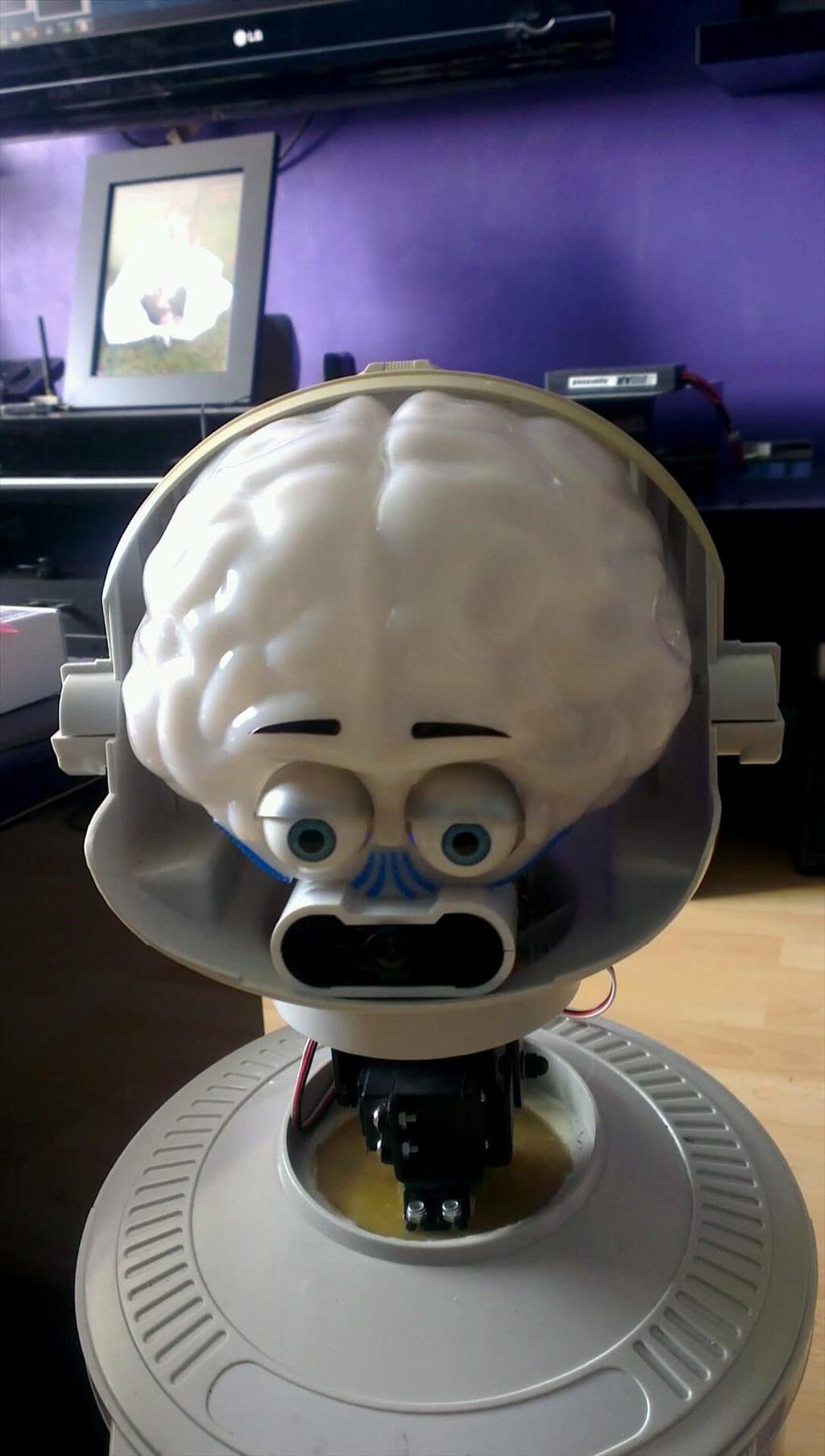
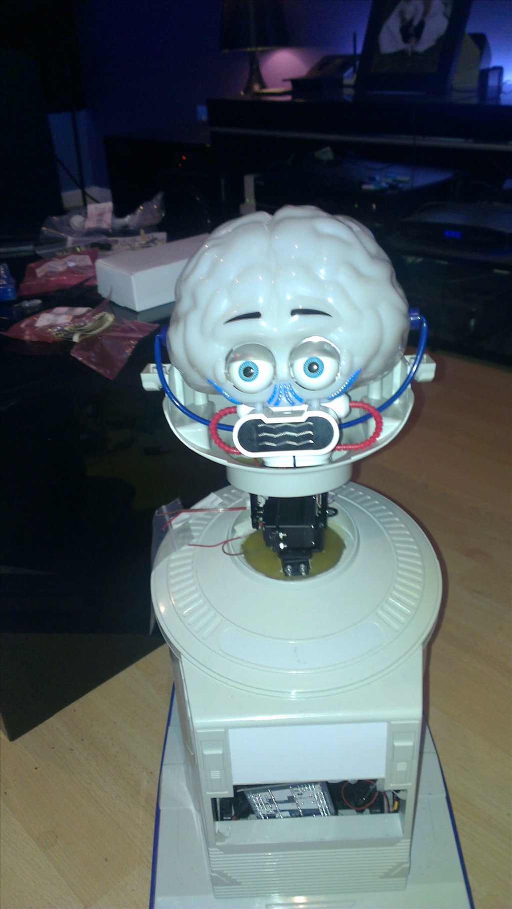
The only other slight modifications to be made to him are to convert the head to tilt & pan which will involve having to give him a small neck.
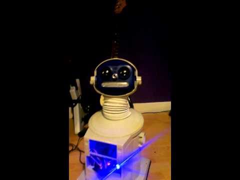
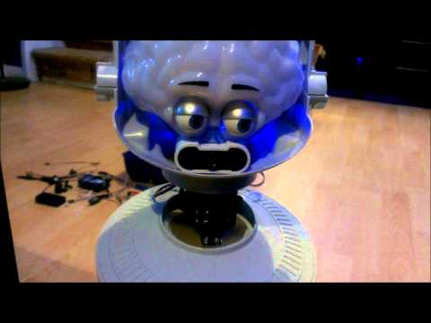
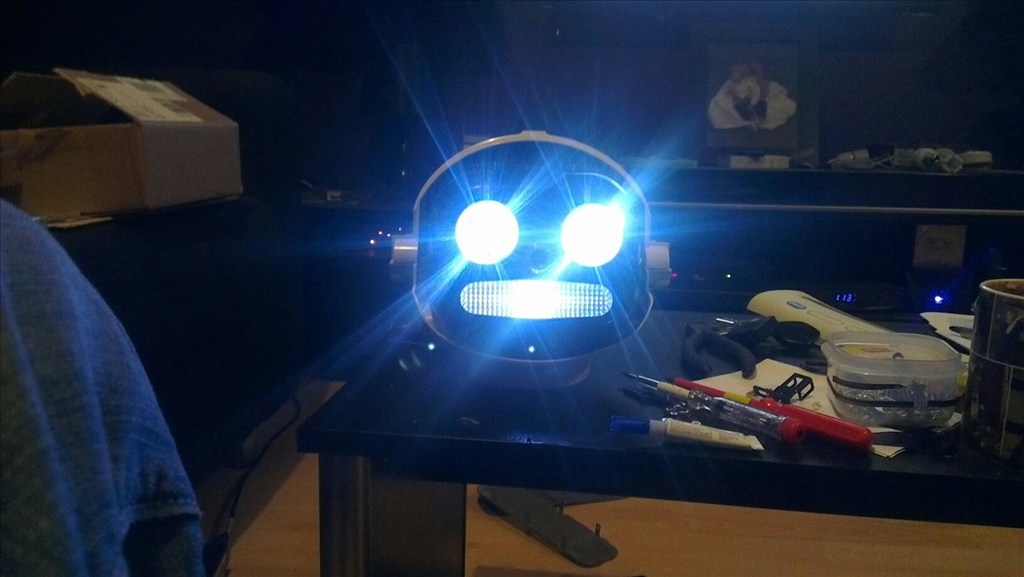
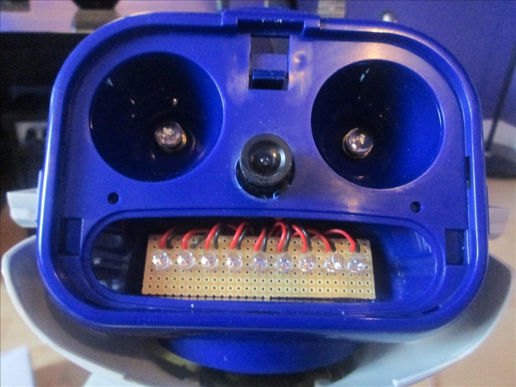
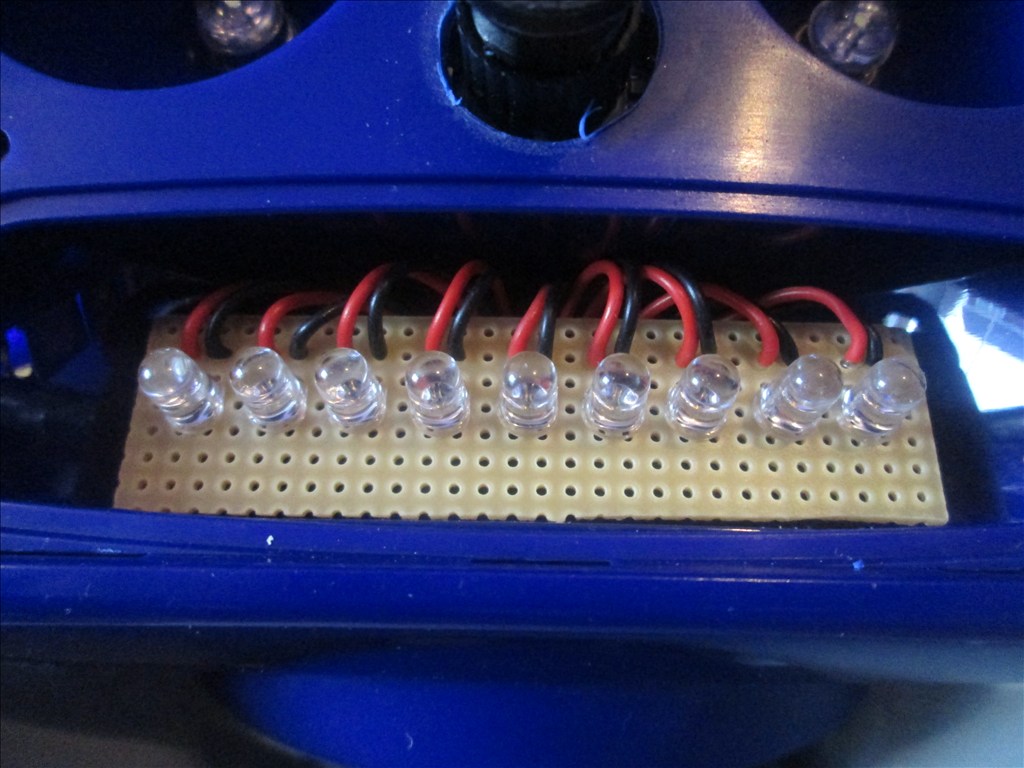
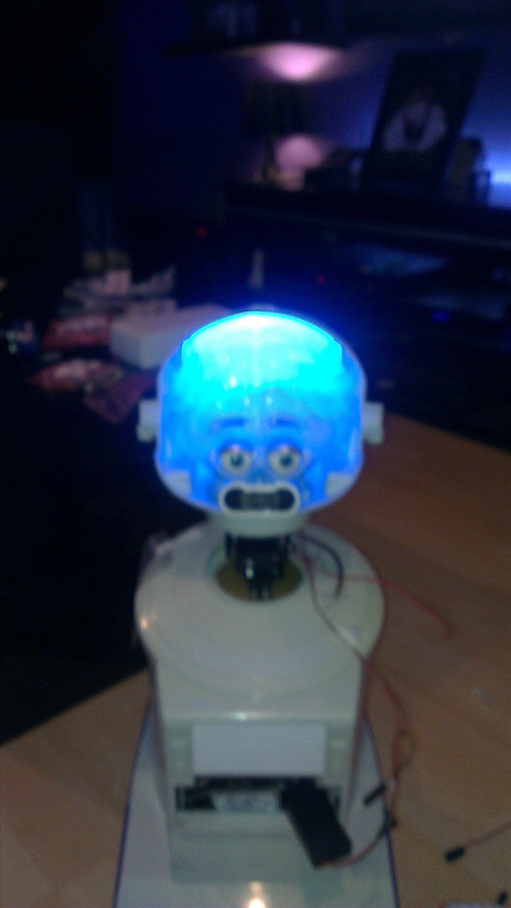
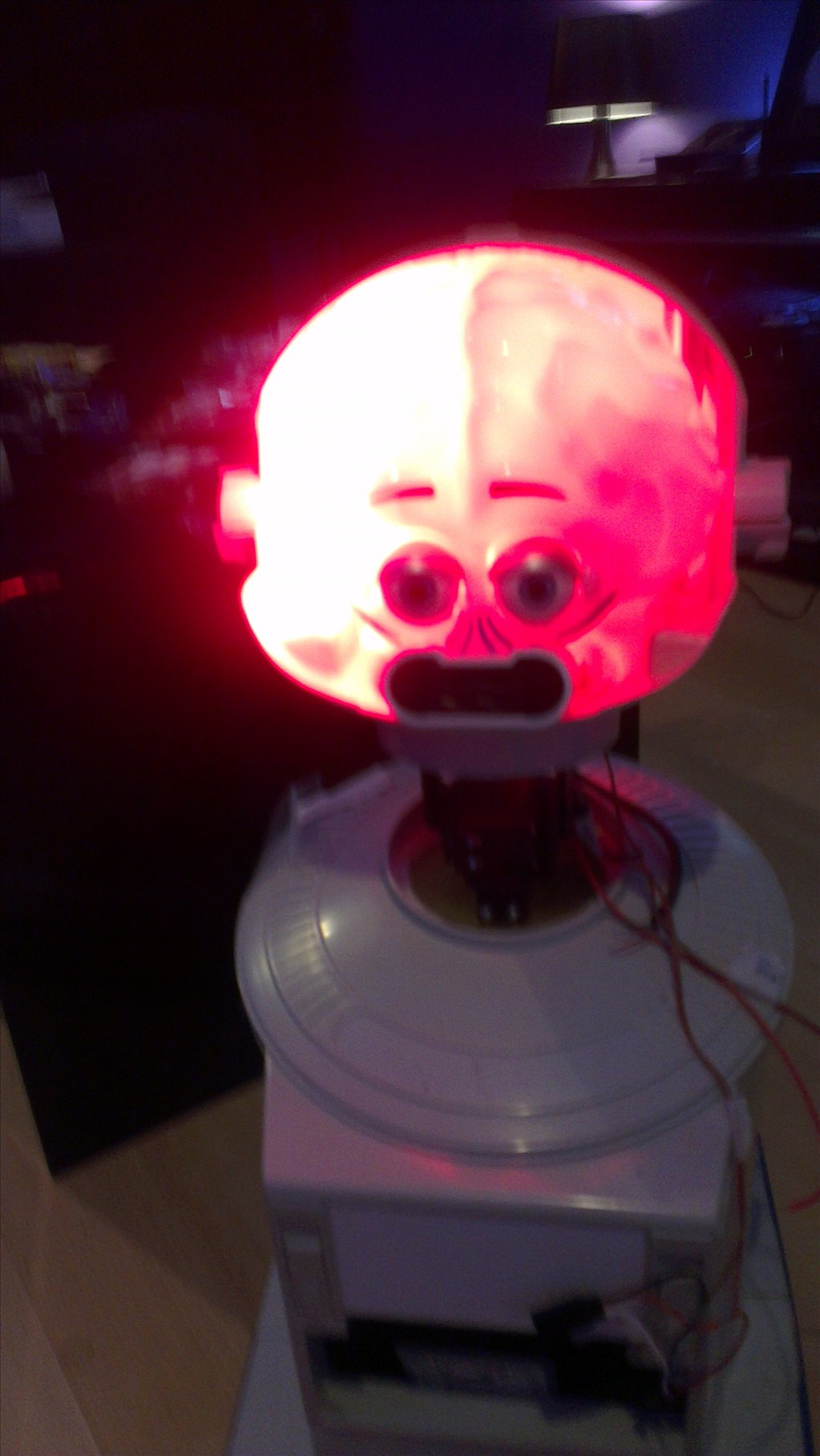
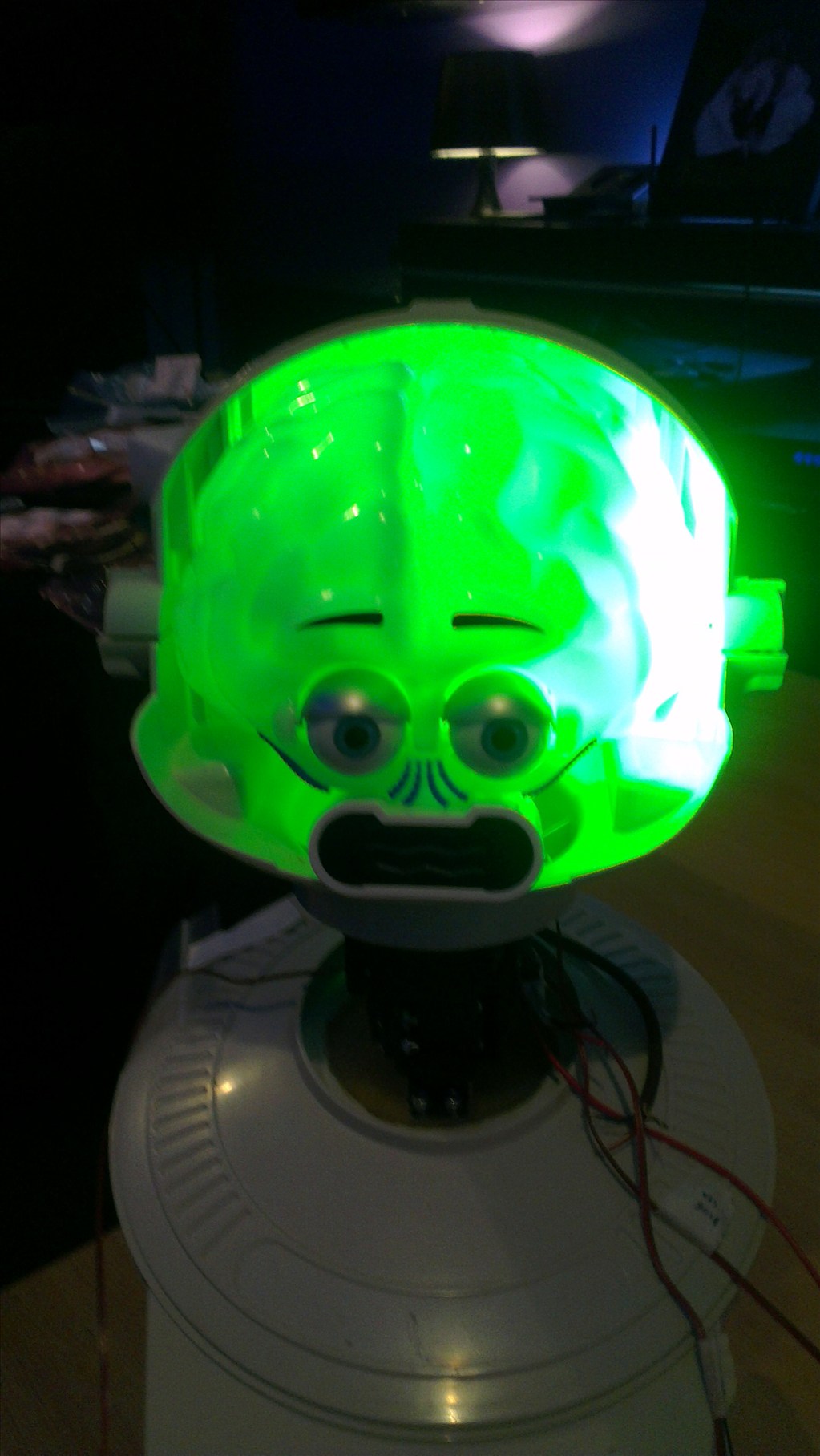
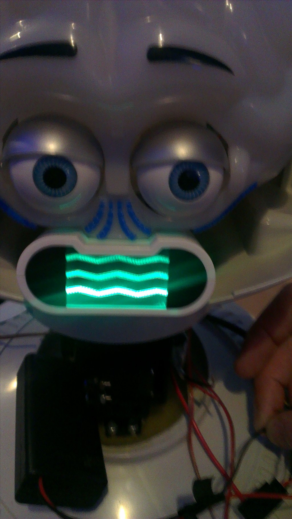
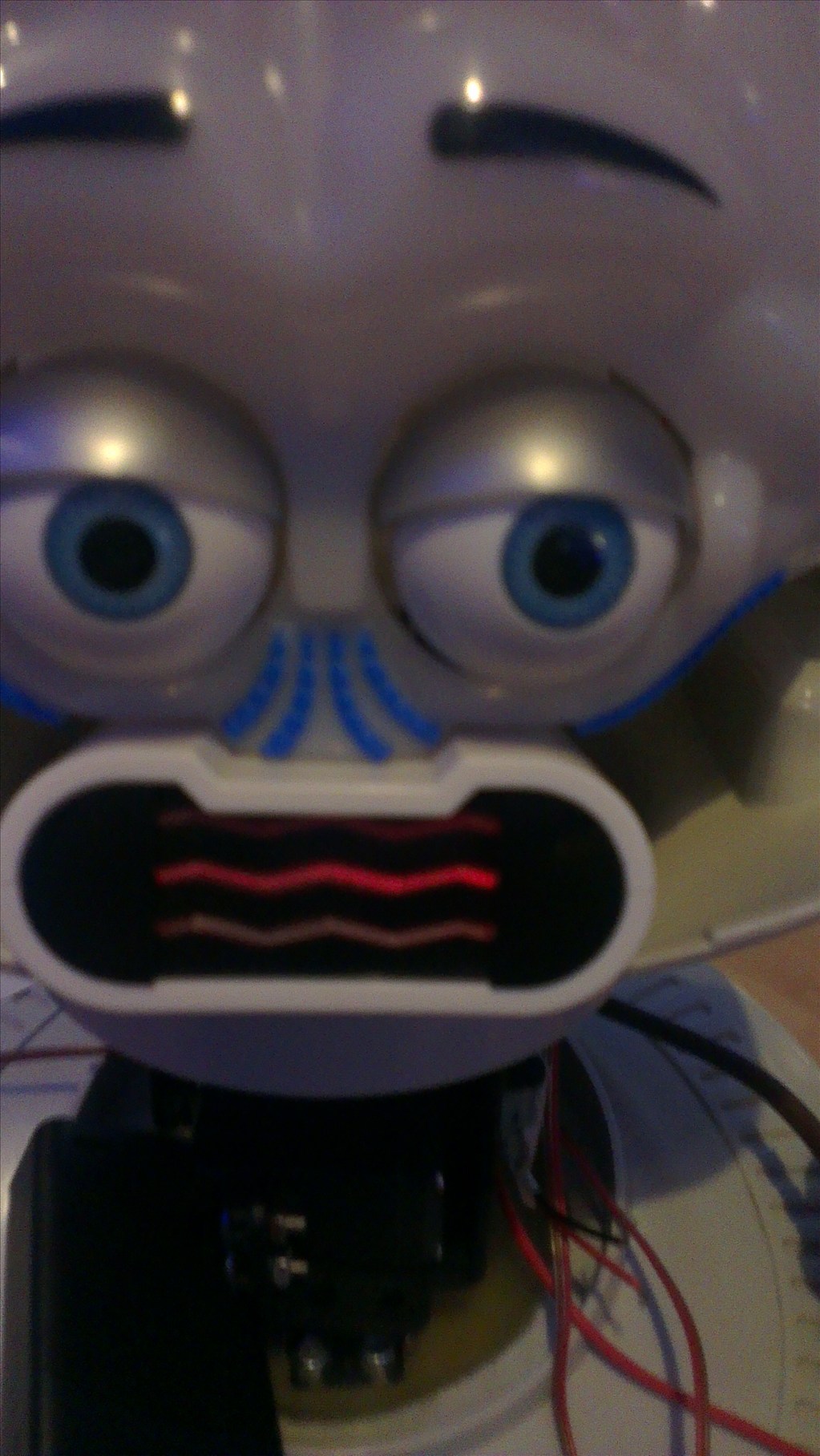
The head will include the camera. I haven't yet decided to fit it in one of his eyes or to make it his nose. The issue to overcome with this is the blue tint on the bubble head. The mouth will have a light or some lights in which flicker when he speaks.
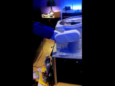
The arms will be given some life with servos at the shoulder joints and the elbows provided I can get them to fit in there nicely.
Ultrasonic sensor will be in his chest, probably on a servo to give a wider view.
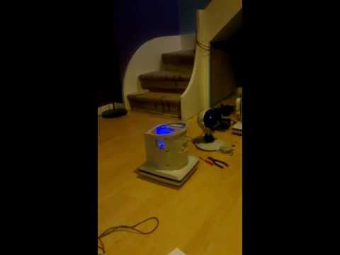
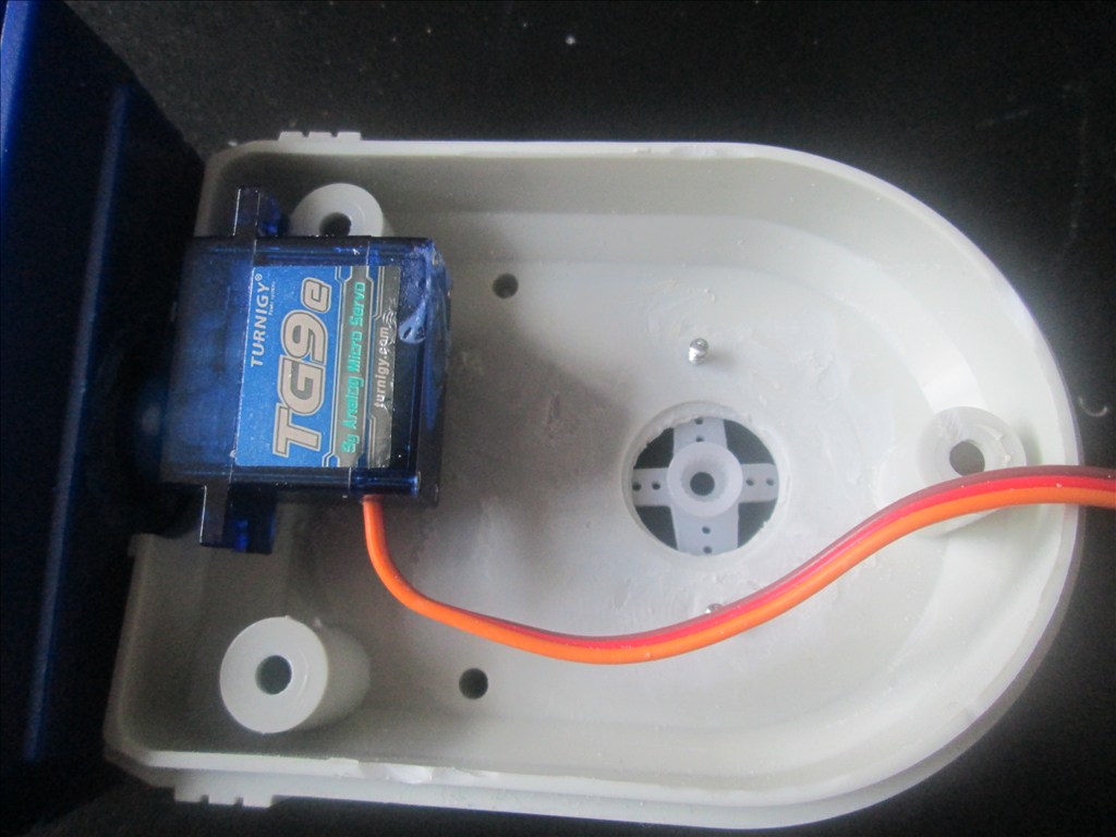
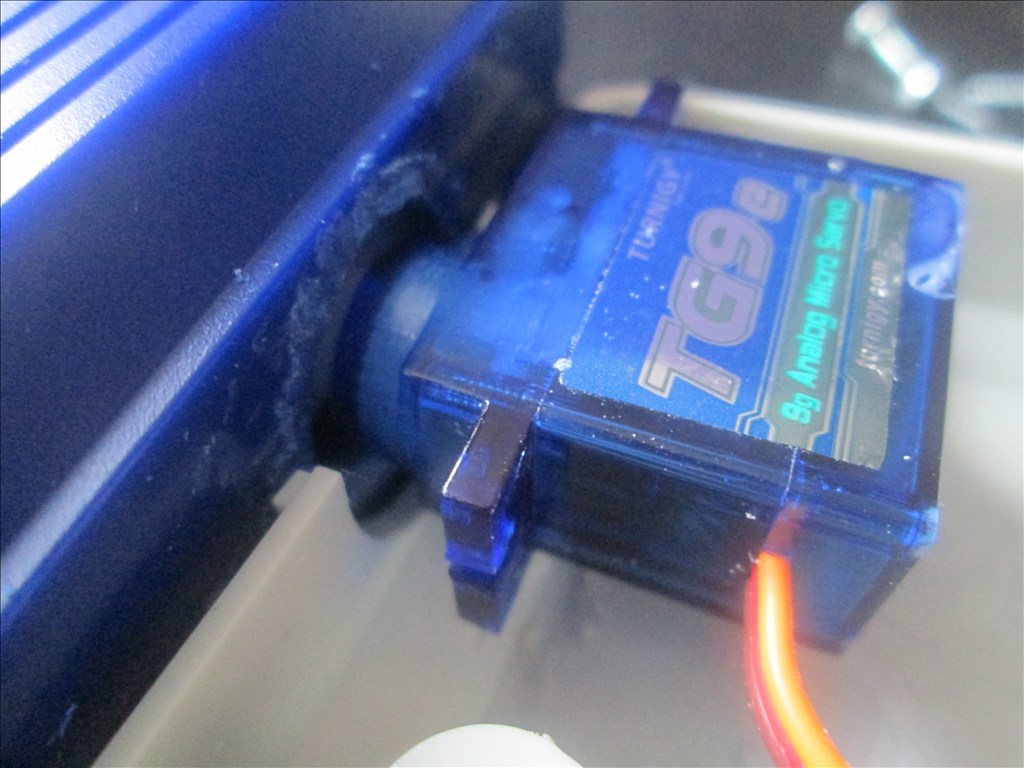
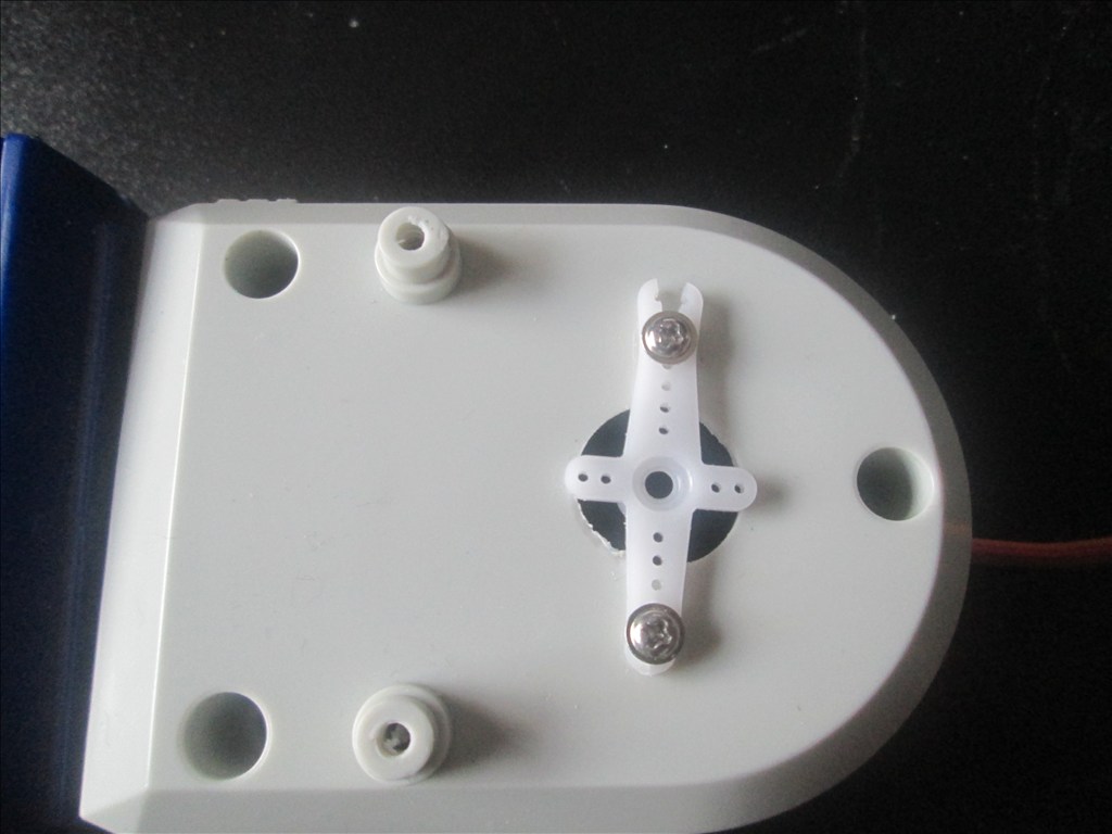
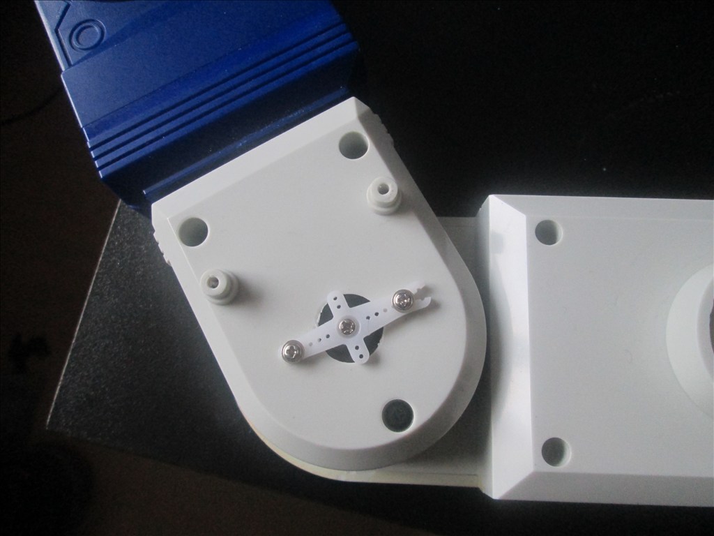
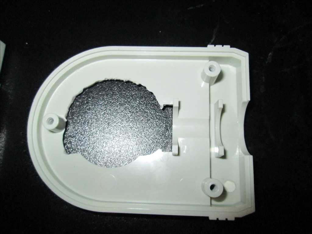
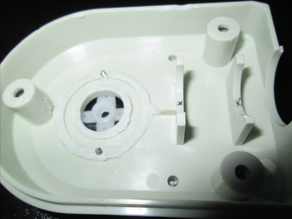
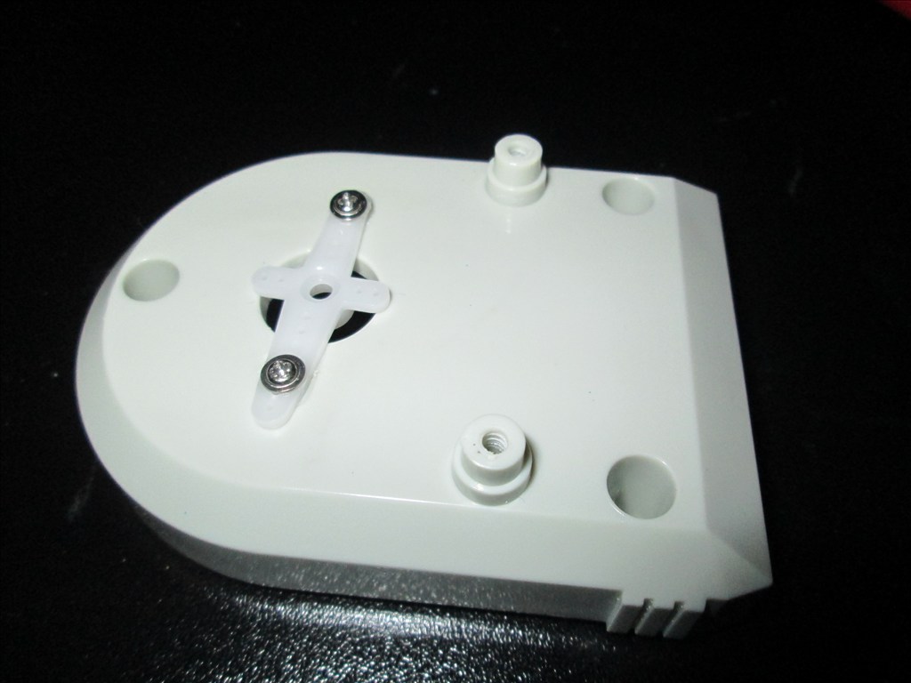
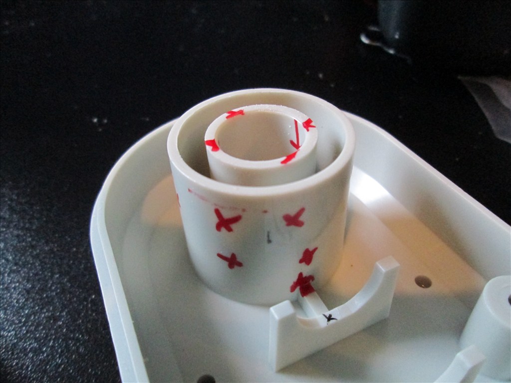
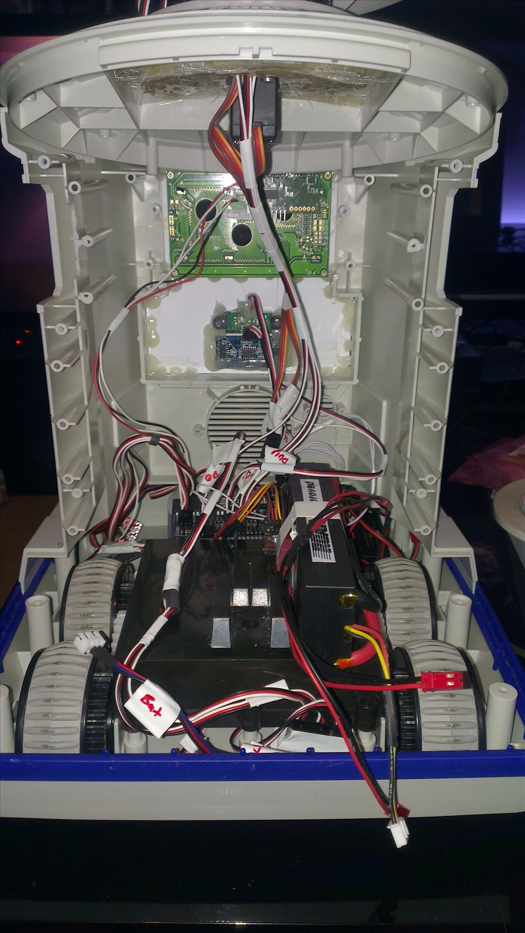
Original drive wheels and gearbox seem to be in very good shape so will plan to reuse those and just replace the existing motors for the modified servos if they can manage the task.
Speaker and microphone will be in the original positions - if it's not broke why fix it?
Not too big a project but enough to give me a test, help me learn and bring an old robot back to life.
Discover more robots
Linux's Project Omega Status
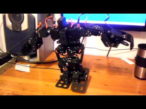
Kenny's Humanoid #2

Sometimes it decides it wants to move in circles. I think it's the HBridge not the EZB as it'll do it before the EZB is connected (in fact it was doing it when I last tried to use it with a battery that was screwed and only had 4v in it). But a little work around solves the problem.
It's the TB6612FNG Motor Controller which I don't read about often so no idea if it's a common issue or not...
Might try another motor controller ,guess to see if you still have the problem
Everything indicates that it is the motor controller but it's fine 4 out of 5 times, maybe even 9 out of 10 times so it's not worth the extra cost or the hassle of rewiring. If it cause that much of a problem I'd throw a switching circut in there to disable VM until connected then a quick and easy Set(D#) before the Forward command.
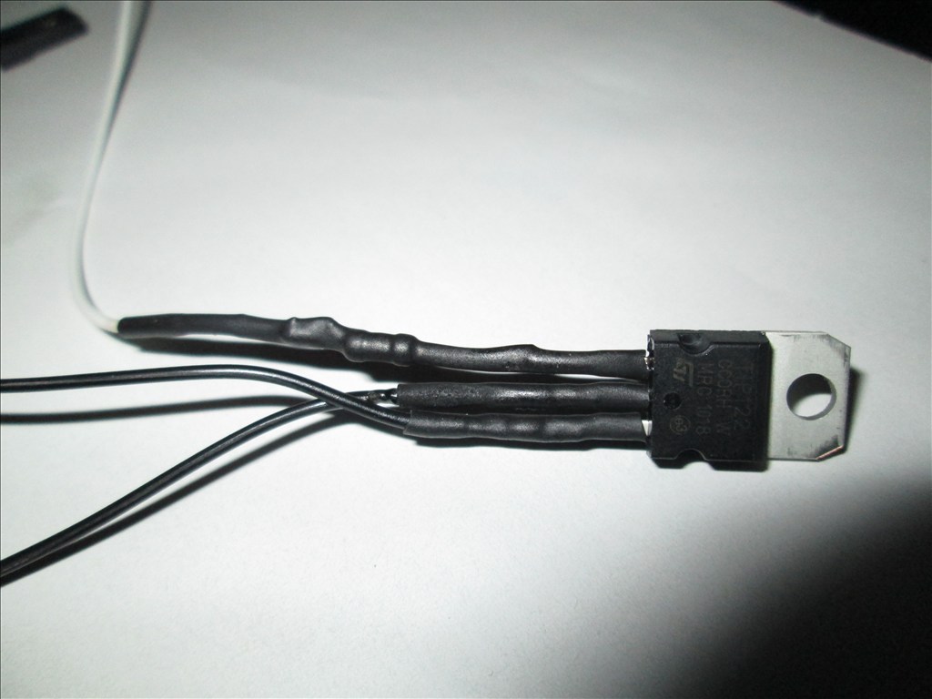
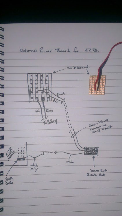
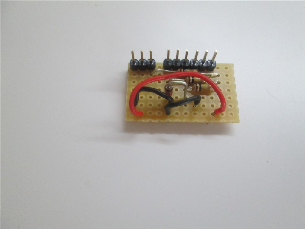
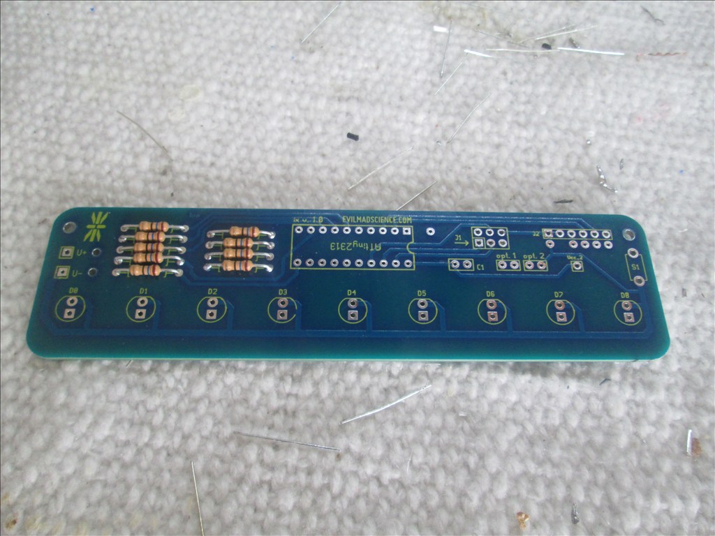
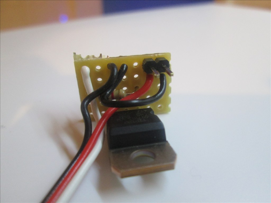
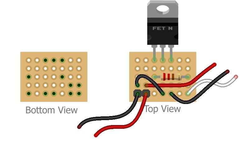
I just decided to redo one of my TIP122 Transistor Switching Circuits (mainly because I needed a break from working - there is nothing wrong with the 2 that are already in this bot). So now's as good a time as any to do a small tutorial
Parts needed: 1 x TIP120 or TIP122 Darlington Transistor 1 x 1k ohm Resistor 1 x Small Piece of Strip Board (7x5 holes) 1 x Pin Header (1x2) 1 x servo Extension Solder Soldering Iron Cutters
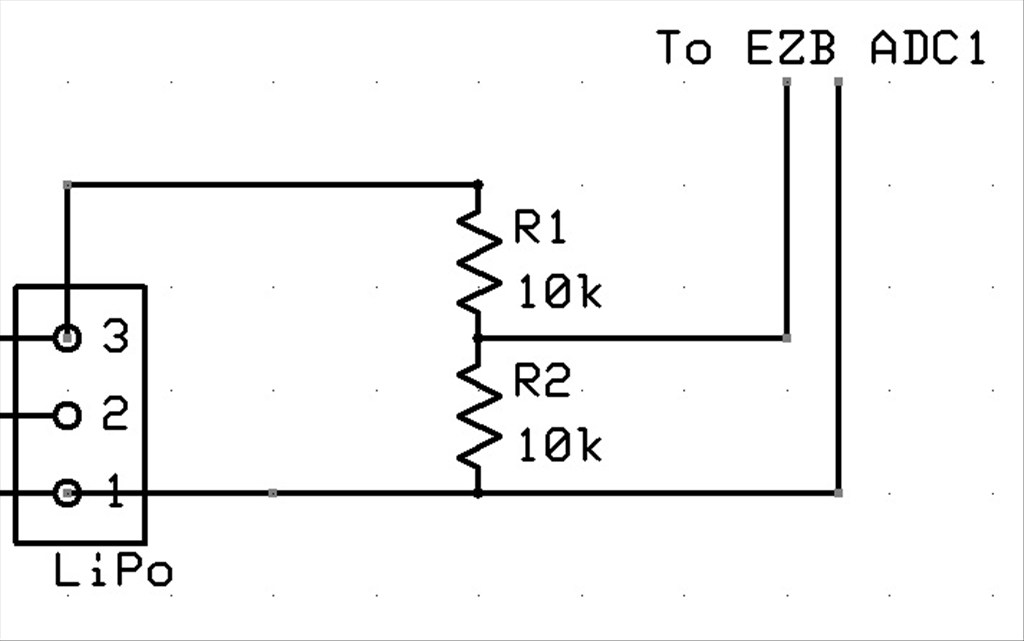
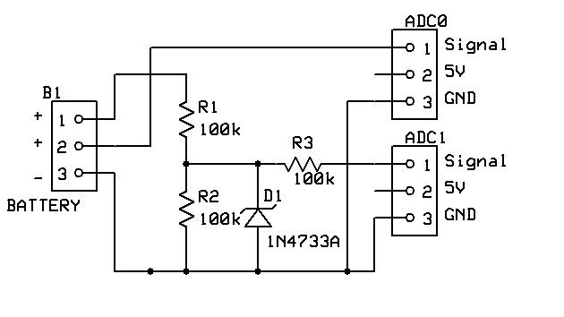
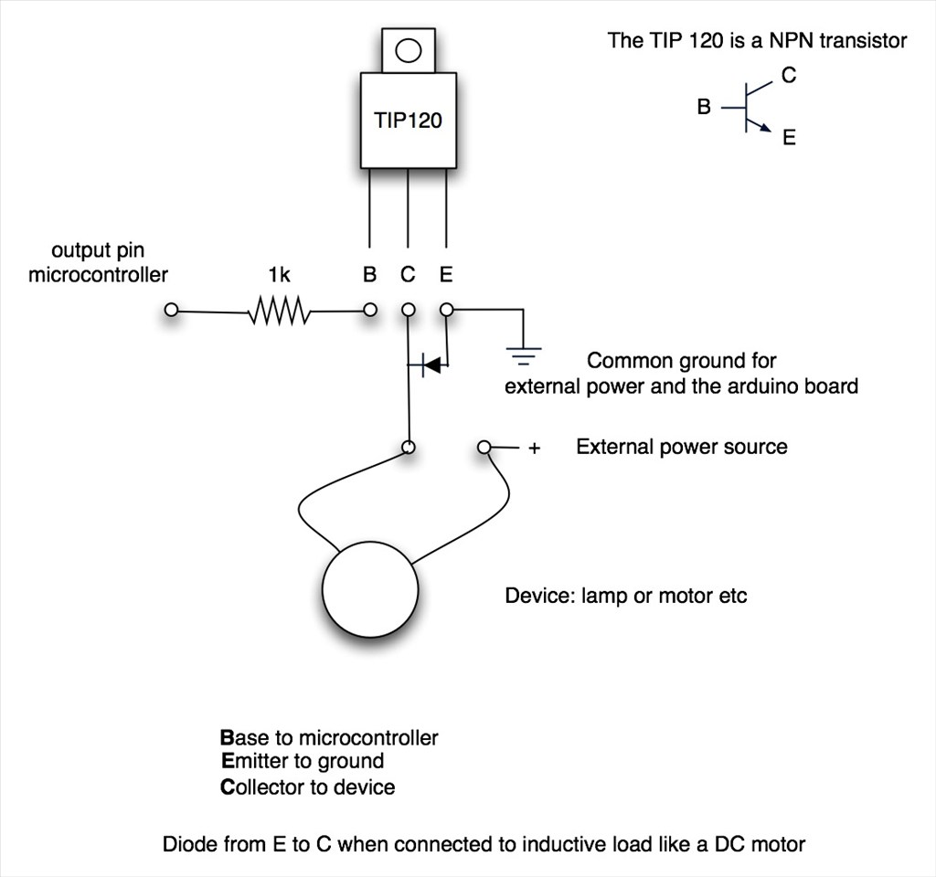
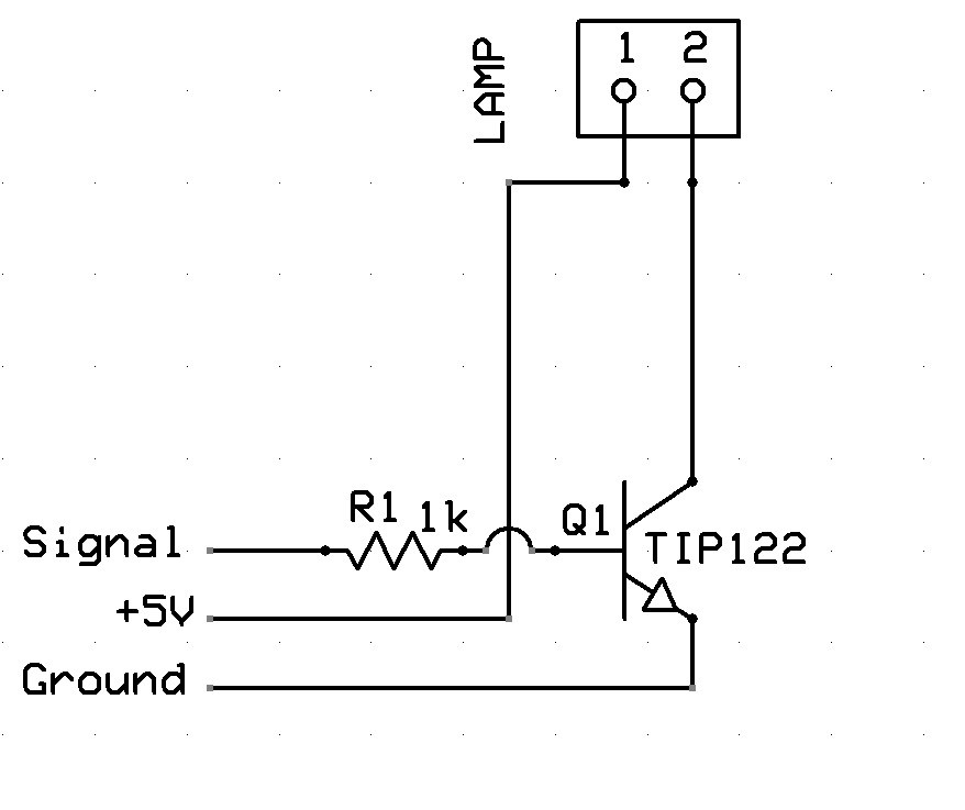
The Schematic:
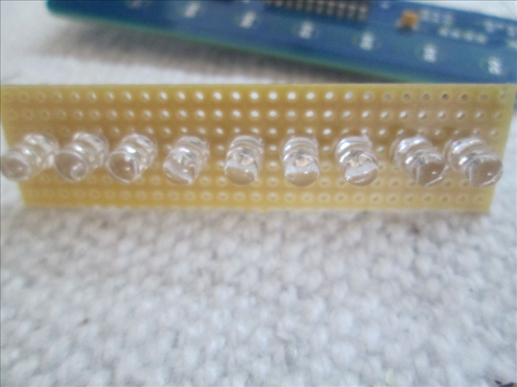
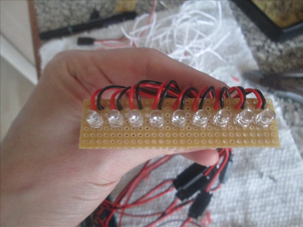
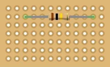
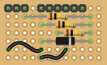
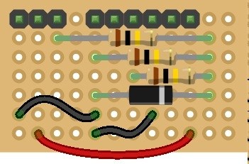
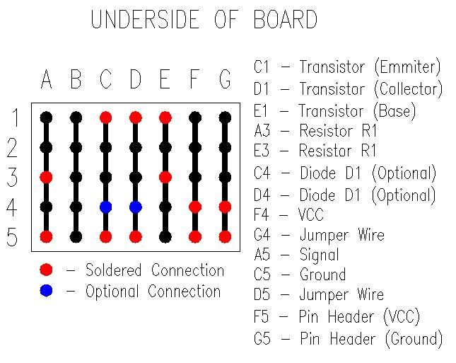
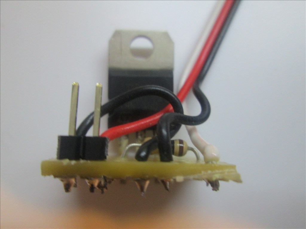
Underside of Board:

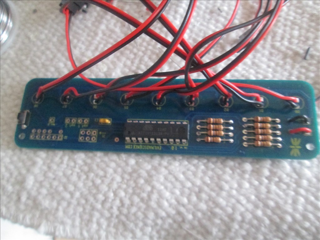
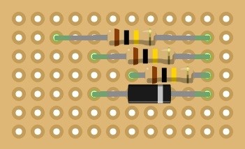
The optional connections are for Diode D1 which will be covered soon (see note at end).Method:
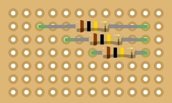
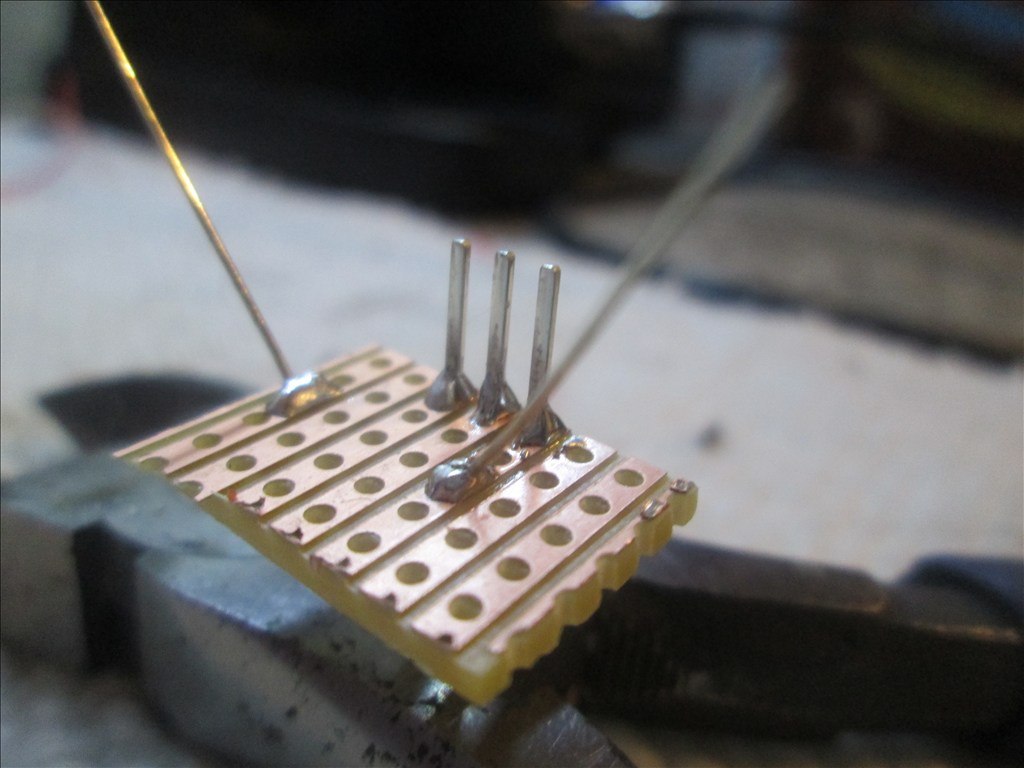
Solder the TIP transistor to the strip board so each pin is on a separate strip of copper
Solder the resistor from the Base of the transistor to a spare copper strip
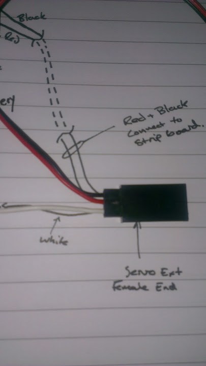
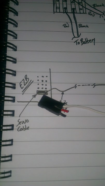
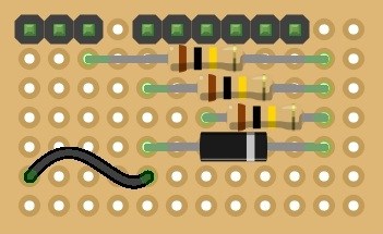
Cut off the end of a servo Extension and strip back the wires
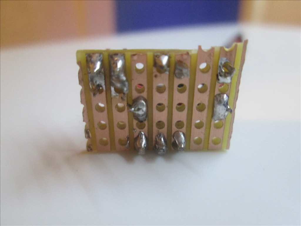
Solder the Black wire of the servo Extension to the strip connected to the Emitter of the transistor
Solder the White wire of the servo Extension to the strip connected to the end of the resistor (not the transistor end)
Solder the Red wire to a spare copper strip
Use a small off cut from the servo Extension and solder one end to the strip of the Collector of the transistor
Solder the other end of the off cut to a spare copper strip next to the Red wire.
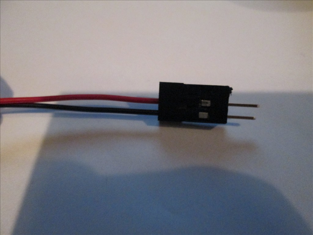
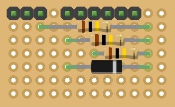
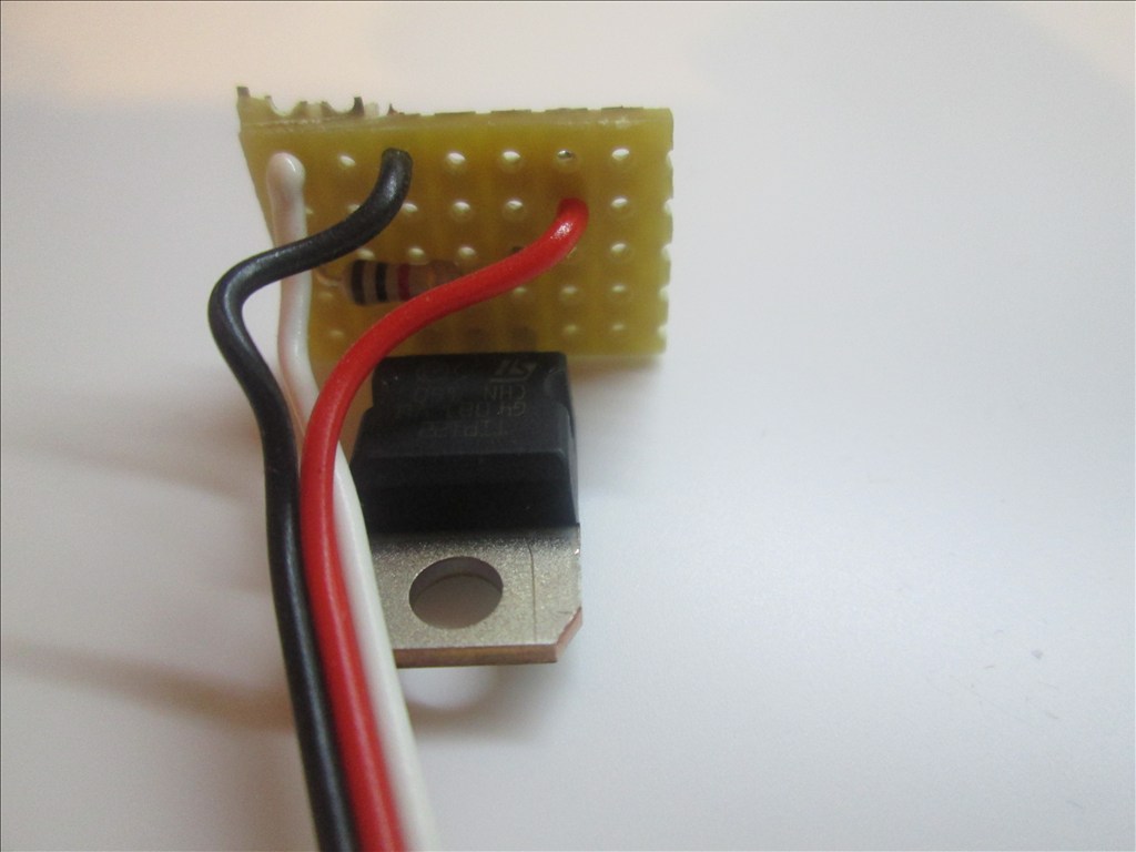
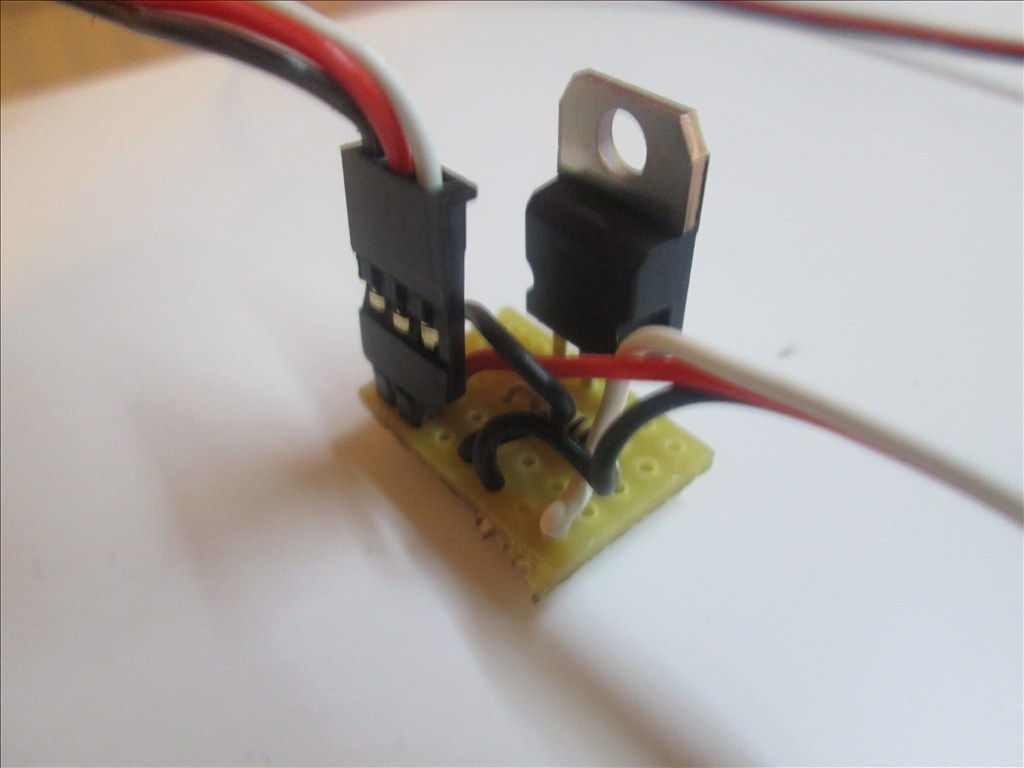
Solder the Pin Header to the copper strips with the red and black wires soldered
Job done. Plug the servo Extension in to a Digital port on the EZB and connect the circuit that needs switching to the Pin Header, I do this with another servo Extension (as I have hundreds of them)
Thank you Rich for your detailed closeups of construction! ALSO, your startup script is a solder(gold) mine of ideas and, it is like your closup pics, EZ to understand...Thanks so much...I too hope to contribute something one day to this forum to assist robot builders
There is a better topic for the switching circuit in the hardware section, which I've updated a few times to now include the diode that may sometimes be needed.
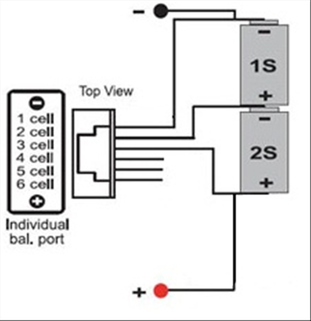
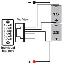
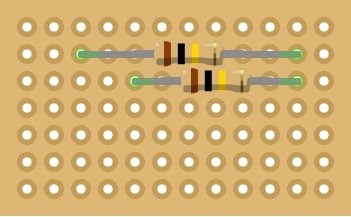
I did start a voltage divider tonight but got a little confused while putting it together and it went a little bit wrong... but it's one I need to make as this project uses one (and while it's apart and I'm still without battery I'm going to remake it).
Rich,
I've been looking over your project and I am very impressed. Thanks so much for posting your code. It gives me something to work from. I am close to being ready to dive in to writing script. This is really a big help to me.
If you ever want to email me, my email is rex.gordon61(at)gmail(dot)com
Rex
I'm all about showing others how to do things and offering as much clear information as possible. It helps that for 15 years part of my job has been writing the technical documentation for post building construction and CDM regulations are a bitch I haven't posted anything close to the amount of documentation I have on this build (a lot would be pretty pointless).
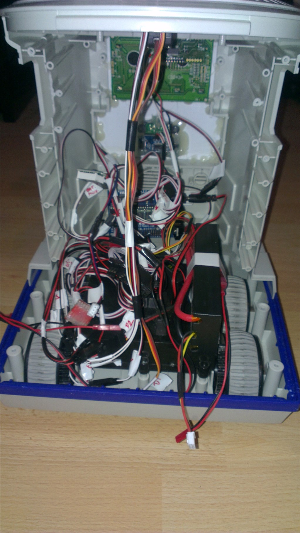
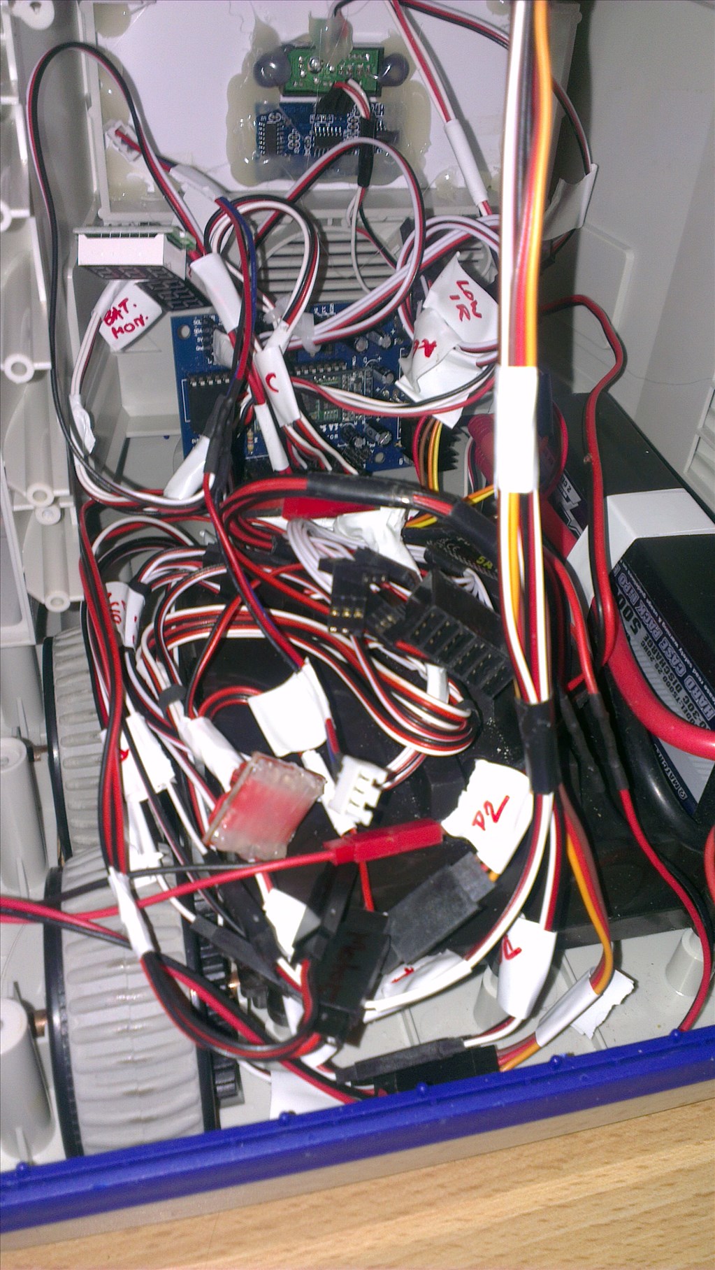
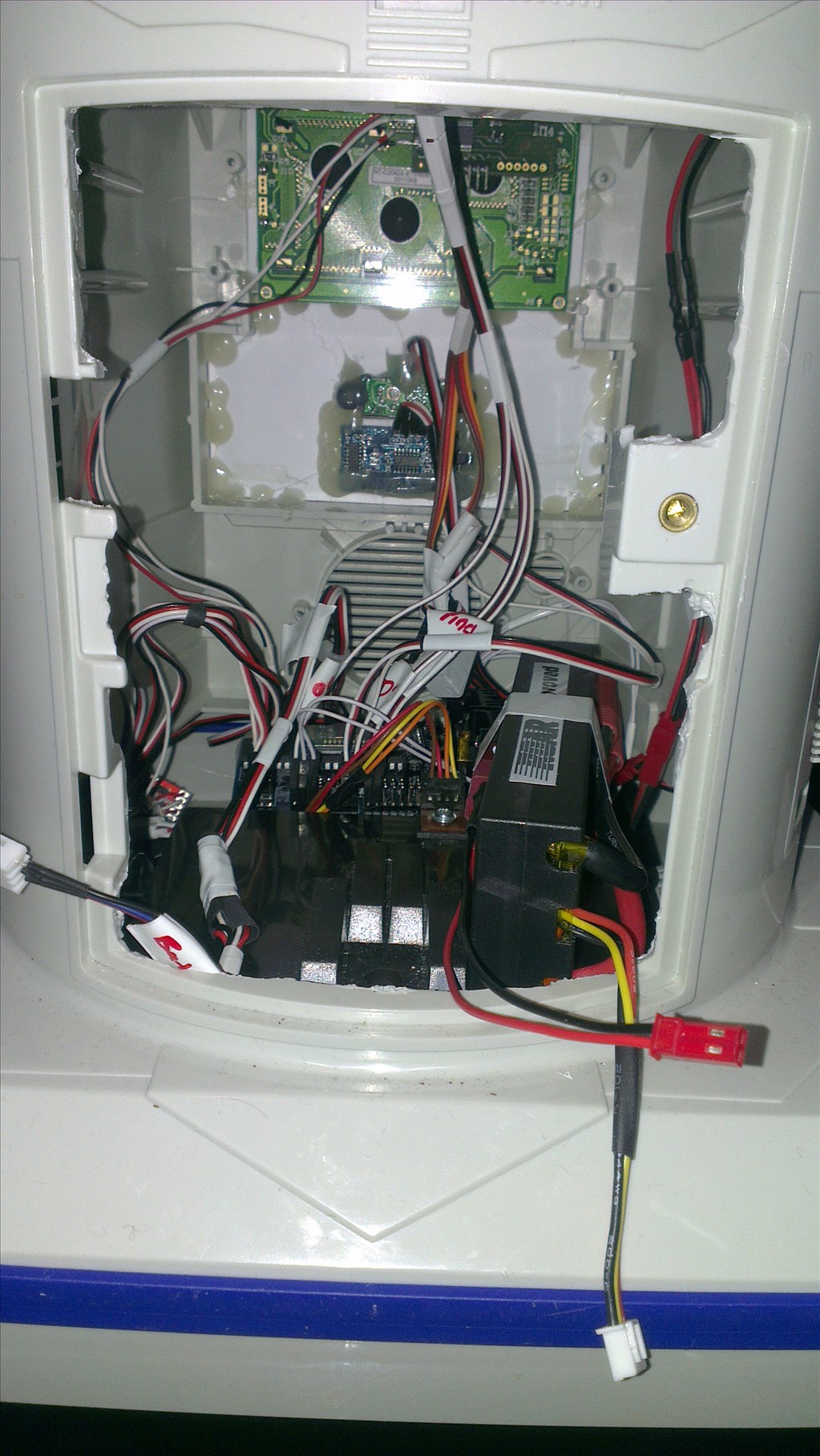
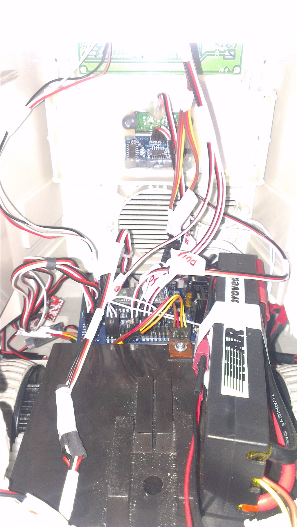
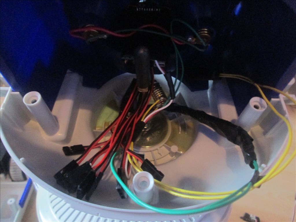
Recently, since draining the LiPo to under voltage I've not been able to do much with the robot so been taking the time to re-write scripts, remake circuits, document it all, label wires and sort out the cable management.
I'm glad people find it useful and hope it helps them build their robot and program their robot.
And, as always if people need to ask things or discuss things off of the forums for any reason my email is [email protected] (I get enough spam so I don't bother with the (at) and (dot) malarkey )
)