


Now I have the EZ-B kit and the Hearoid it's time to start my Showcase thread.
I still haven't decided on a name for him yet, all suggestions are welcome.
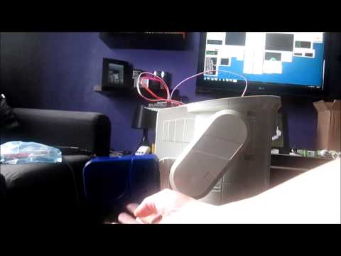
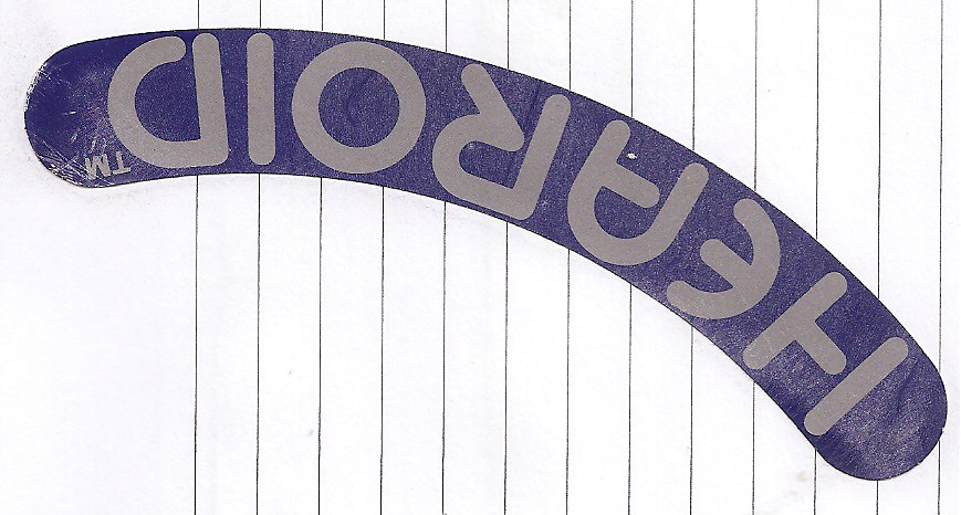
I won this robot on ebay weeks ago, for the past 2 weeks he has been waiting for me to collect him...
Today was the day, a road trip to pick him up and bring him back to his new home...
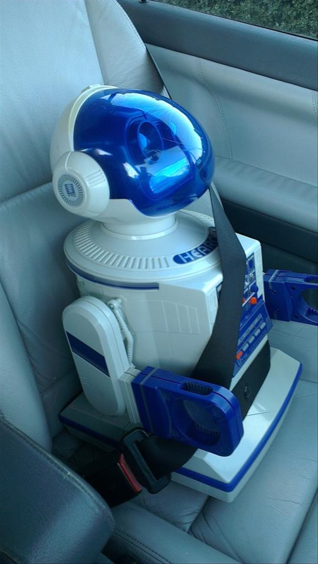
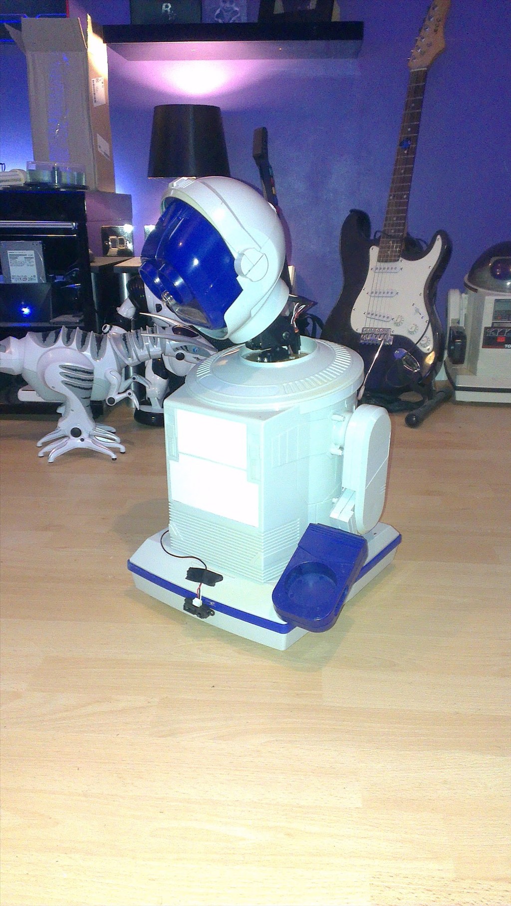
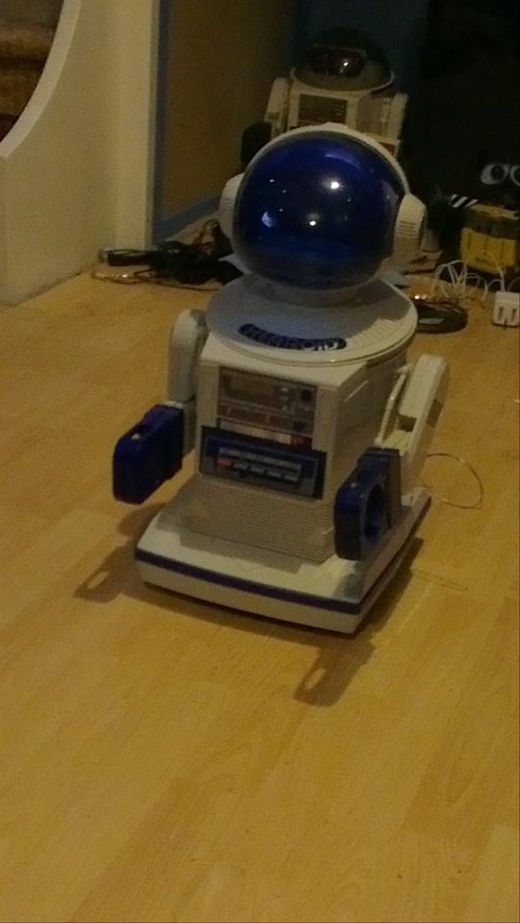
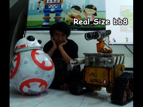
In his new home (with Omnibot and Wall-e in the background totally unaware they are next in line to be opened up)
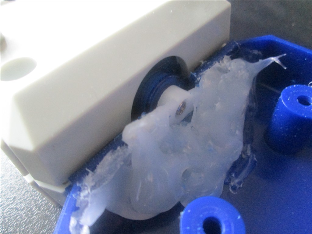
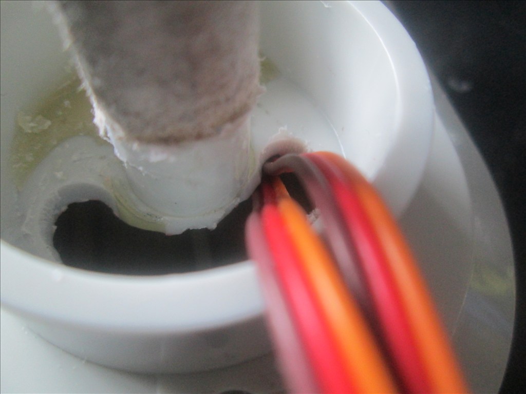
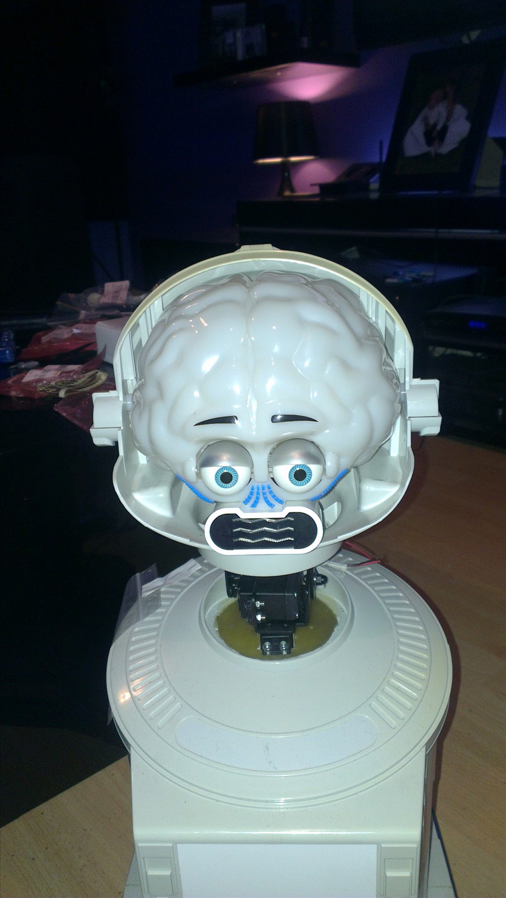
It wasn't long before this happened...
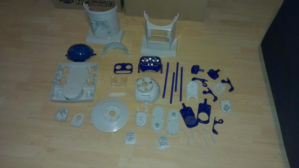
Now waiting to go in the dishwasher to get nice and clean.
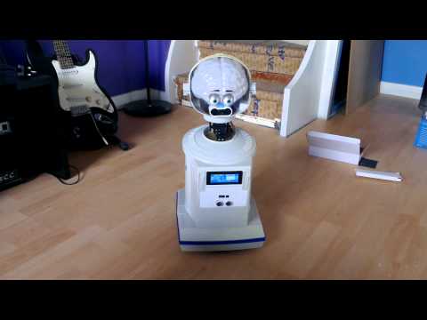
The plan is to make him autonomous, running 24/7 (except for when he knows to go charge himself up) but will also be adding in the various image tracking options.
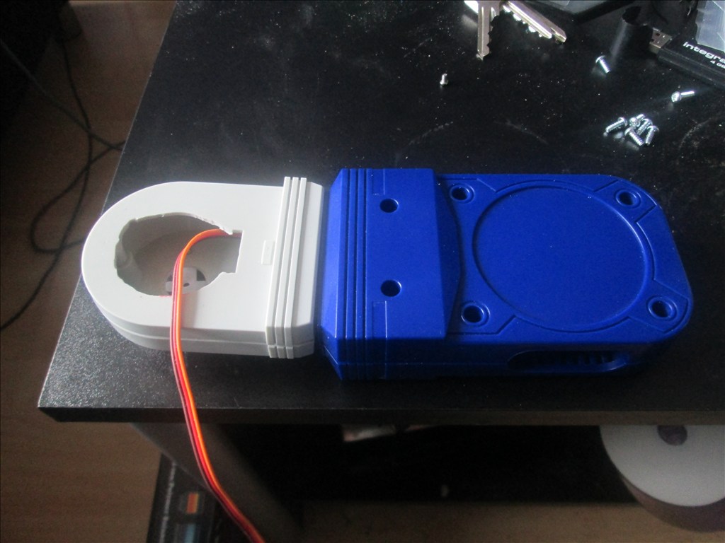
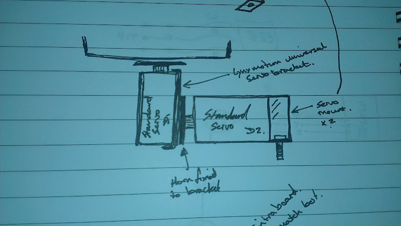
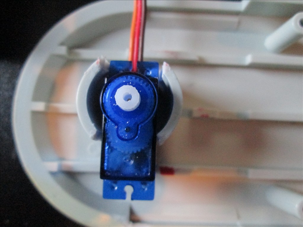
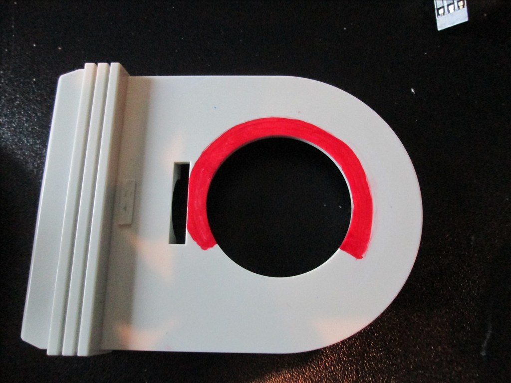
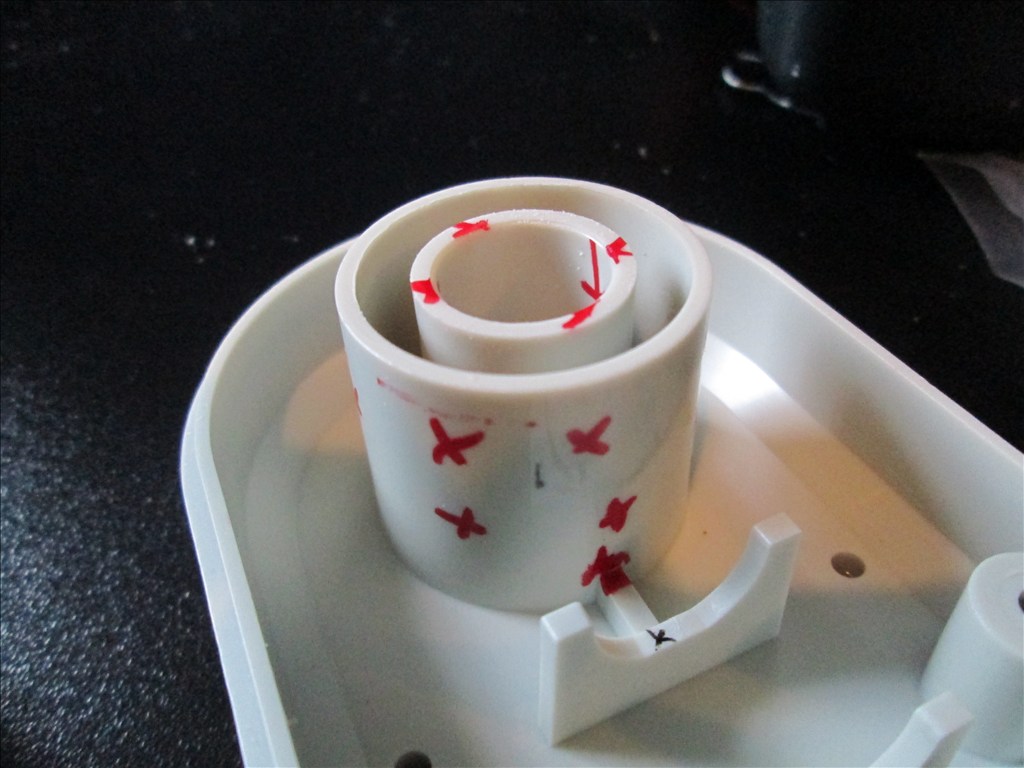
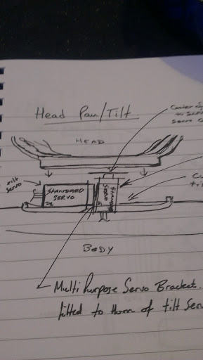
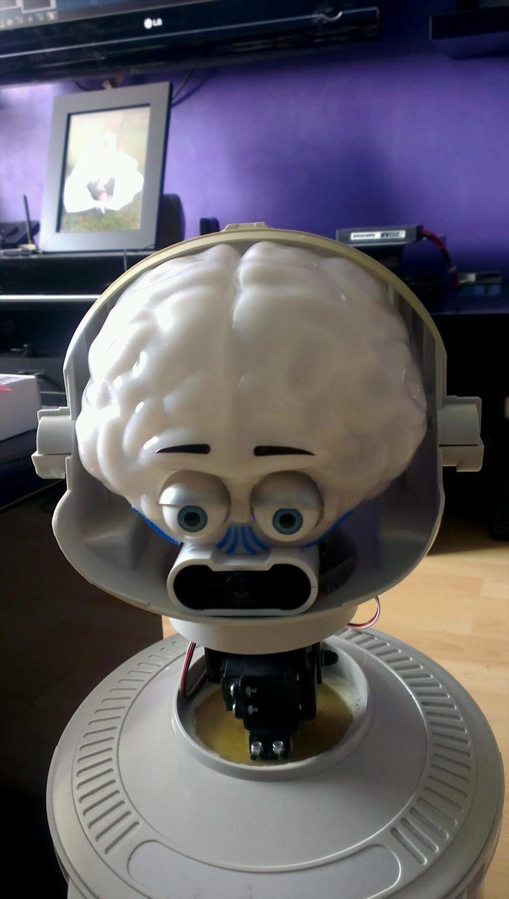
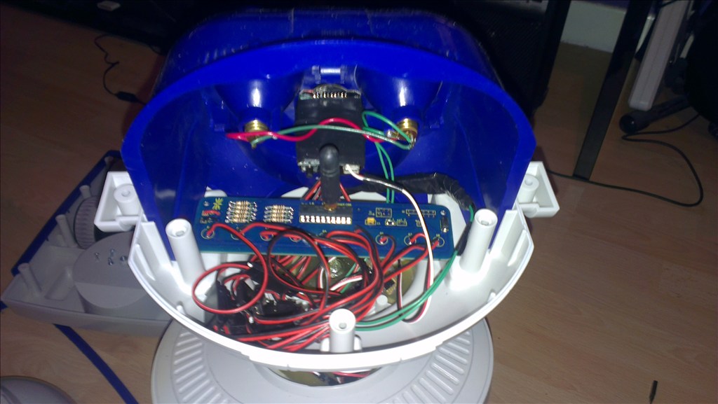
The only other slight modifications to be made to him are to convert the head to tilt & pan which will involve having to give him a small neck.
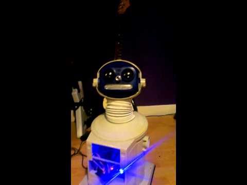
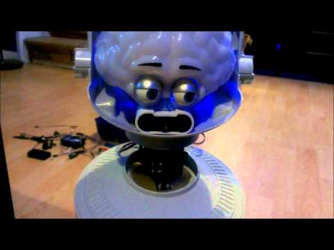
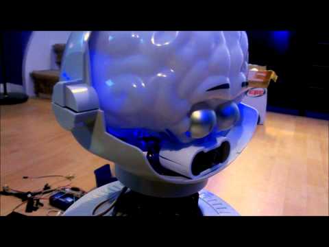
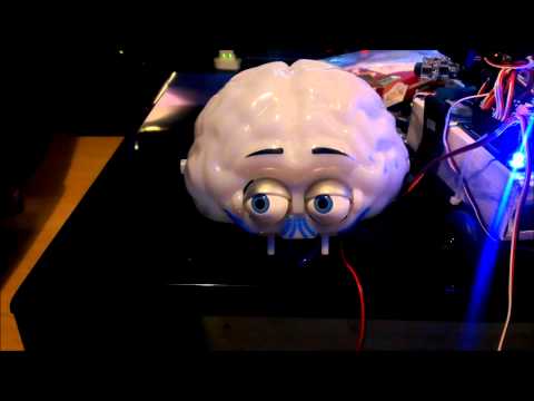
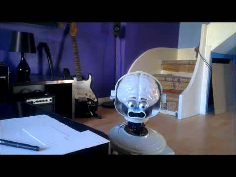
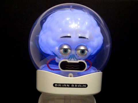
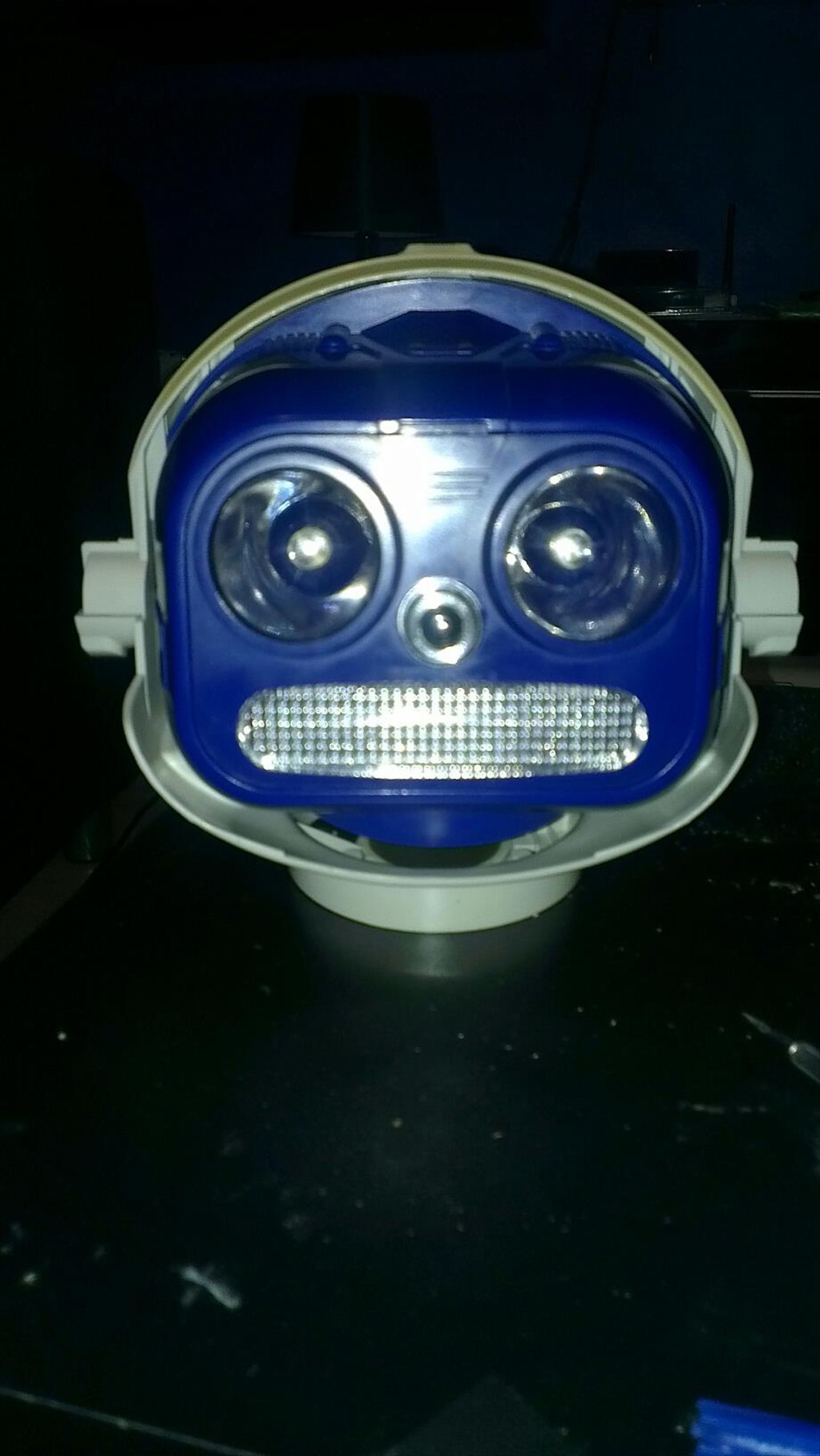
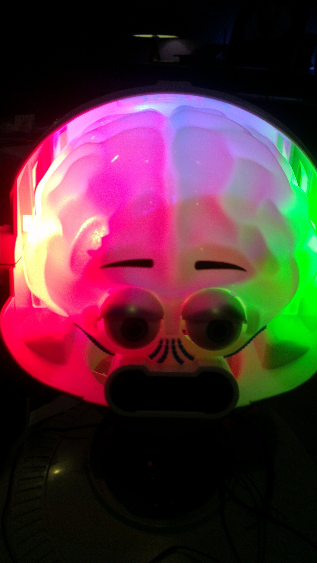
The head will include the camera. I haven't yet decided to fit it in one of his eyes or to make it his nose. The issue to overcome with this is the blue tint on the bubble head. The mouth will have a light or some lights in which flicker when he speaks.
The arms will be given some life with servos at the shoulder joints and the elbows provided I can get them to fit in there nicely.
Ultrasonic sensor will be in his chest, probably on a servo to give a wider view.
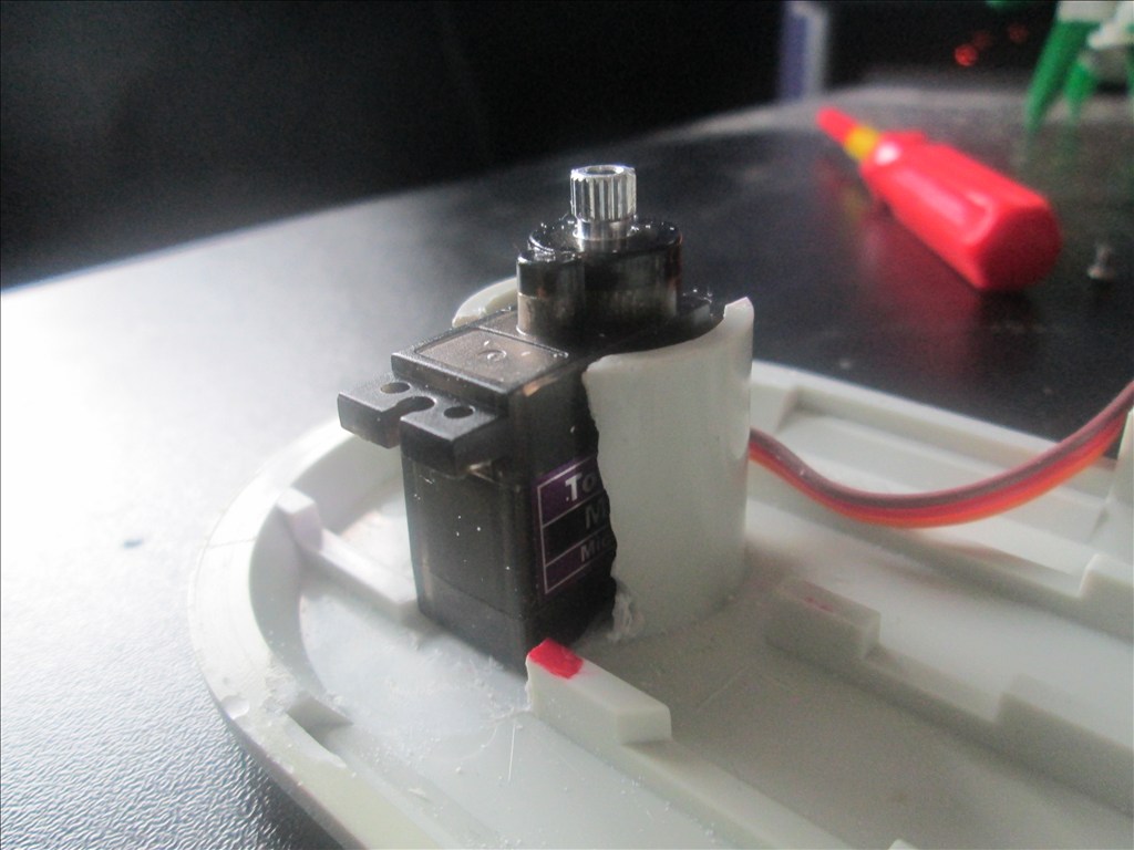
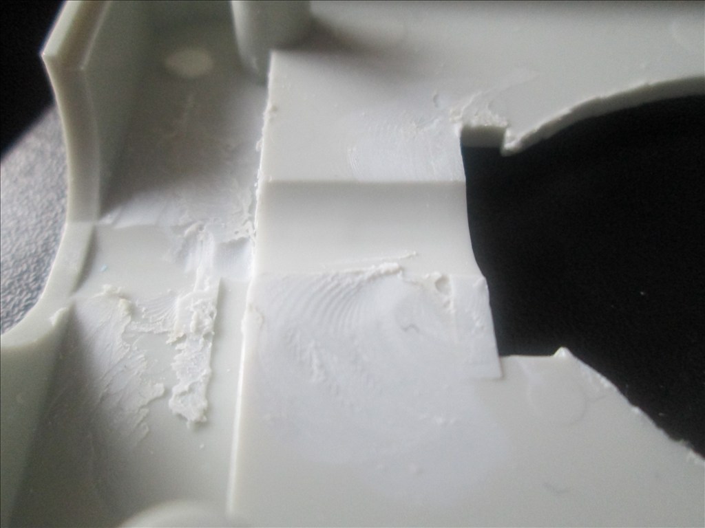
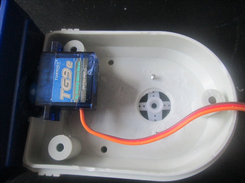
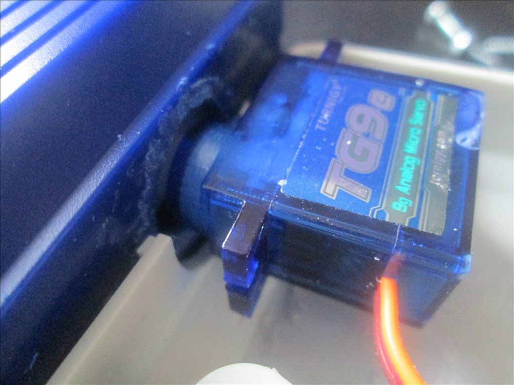
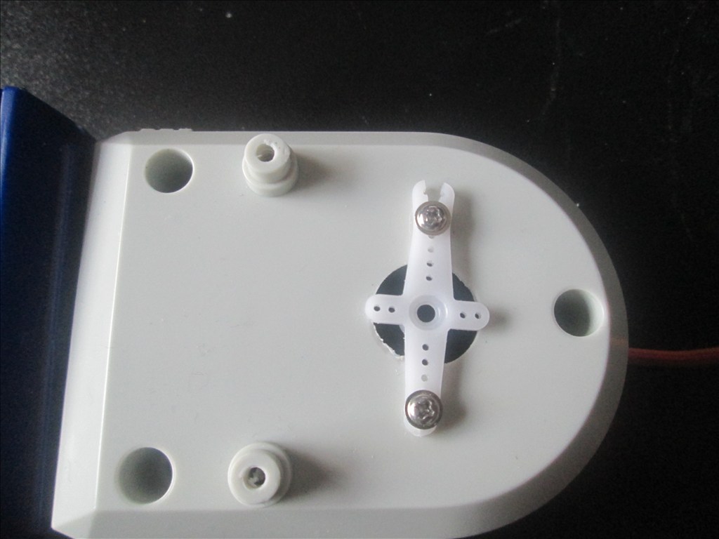
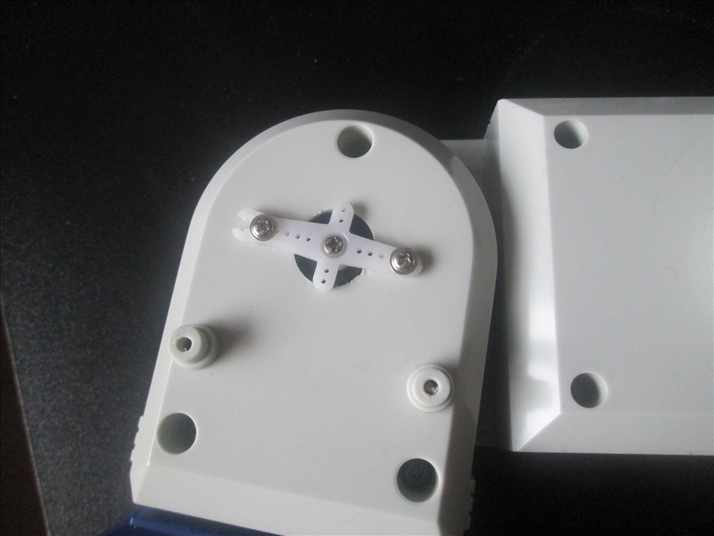
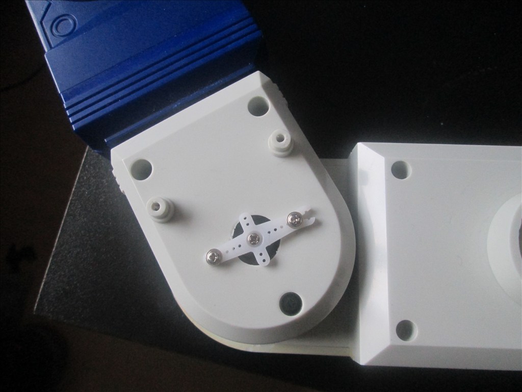
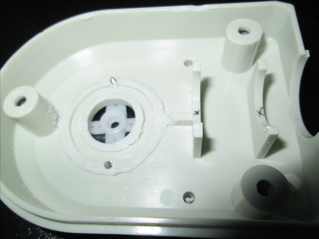
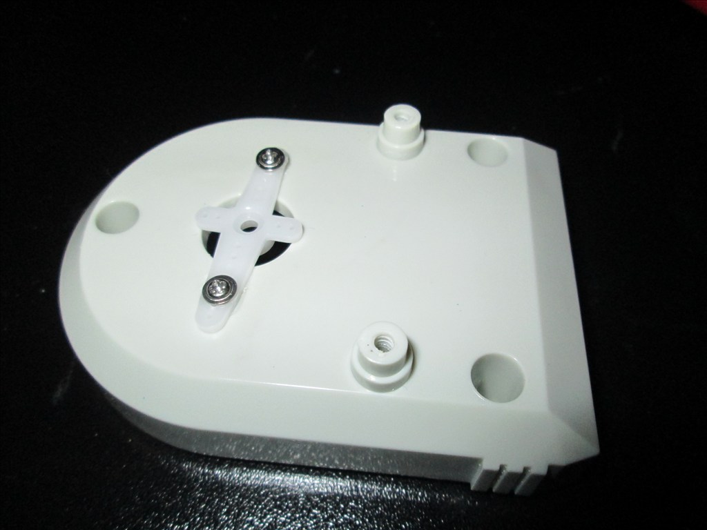
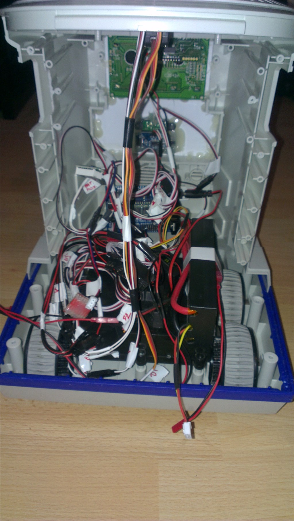
Original drive wheels and gearbox seem to be in very good shape so will plan to reuse those and just replace the existing motors for the modified servos if they can manage the task.
Speaker and microphone will be in the original positions - if it's not broke why fix it?
Not too big a project but enough to give me a test, help me learn and bring an old robot back to life.
Discover more robots
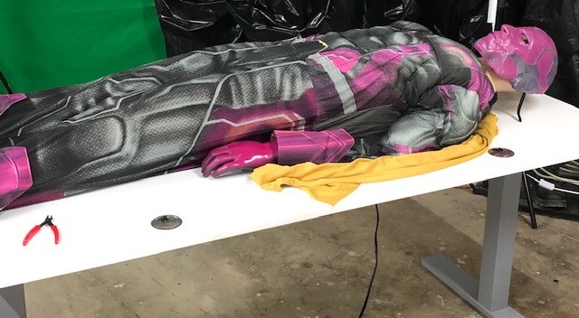
Tmesserschmidt's The Vision (Marvel) Robot Replica
Ericez's Droid For Theater Robot Contest

When I actually scrounge enough money, with has been quite slow to be honest, would you be down if I emailed you any questions I have when I get it? I do understand you basically just said yes in your last post, I just feel obligated to ask for personal allowance, just how I am.
Yep, an open invite to all. Although if its something that may benefit the community its always best in the forum (I tend to check here a few hundred times a day).
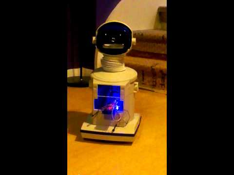
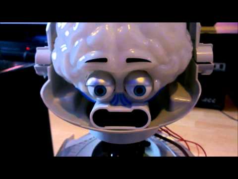
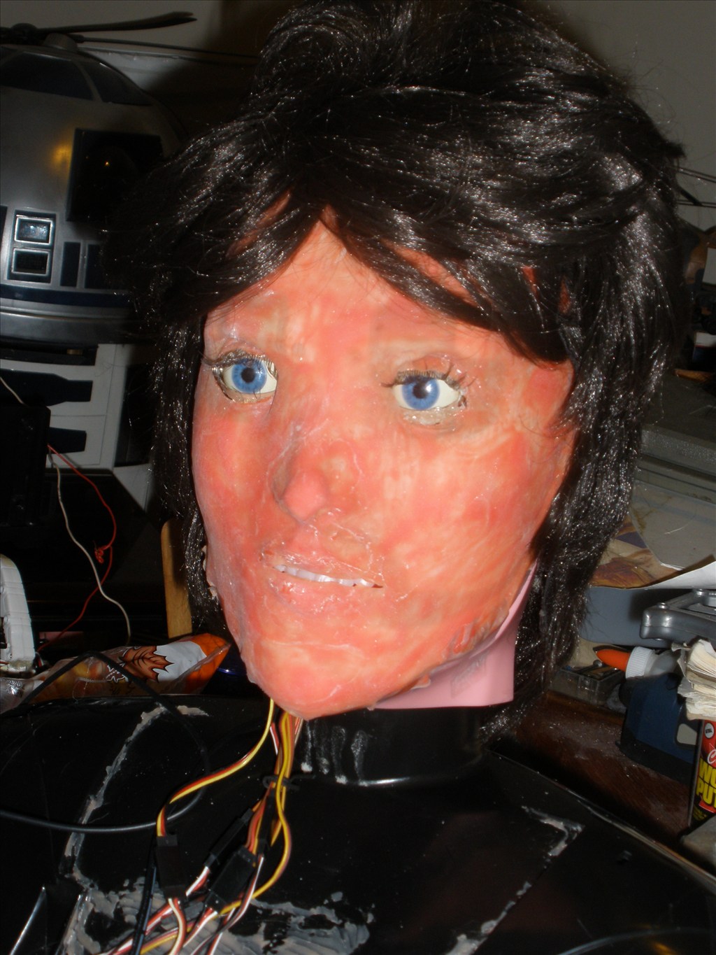
Melvin gets a new mouth
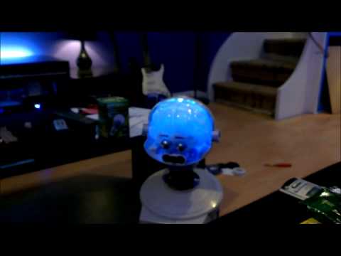
Not much of a write up on this one, I'm too tired to explain it all but a picture paints a thousand words so...
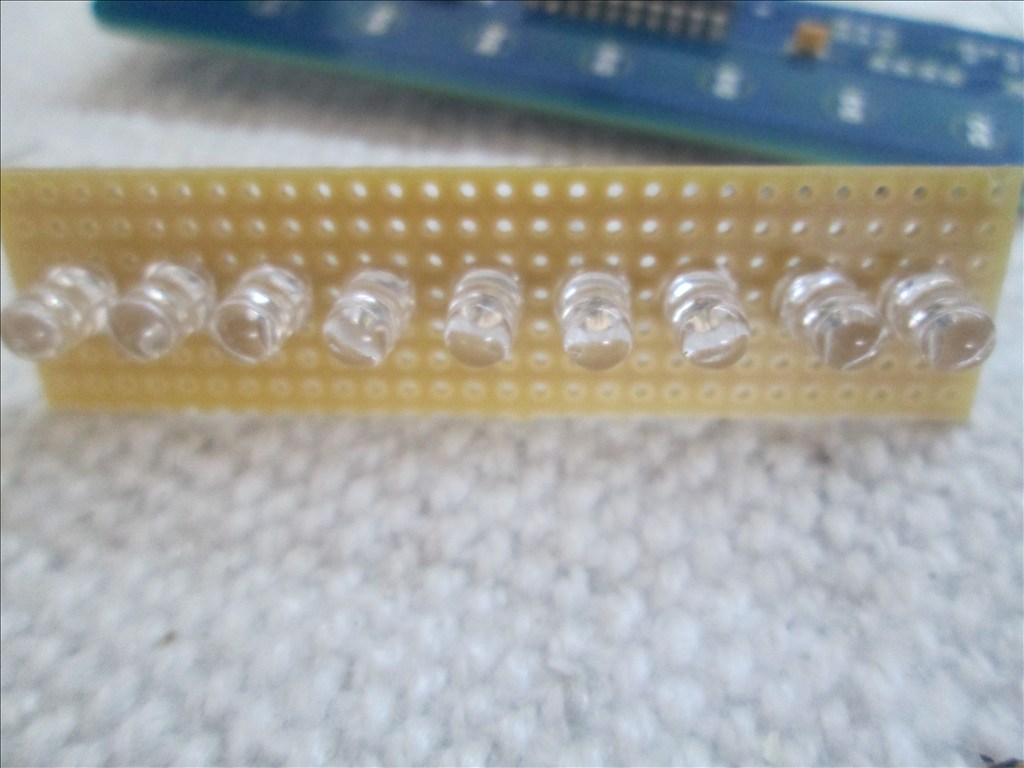
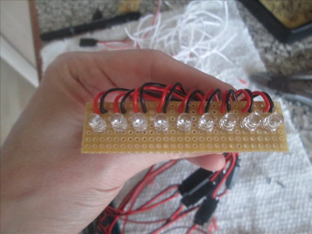
The Evil Mad Scientist Larson scanner.
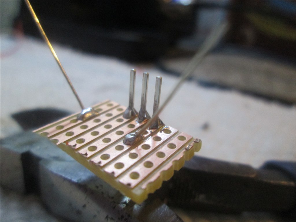
That's too big for the mouth slot so some alterations are needed. A piece of stripboard (my last piece, exactly the right size too) for the LEDs makes it smaller.
Then some servo extension cables cut in half so it can be removed, replaced and makes it just that much easier to fit.
The other half on to the circuit board
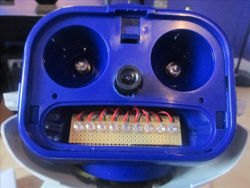
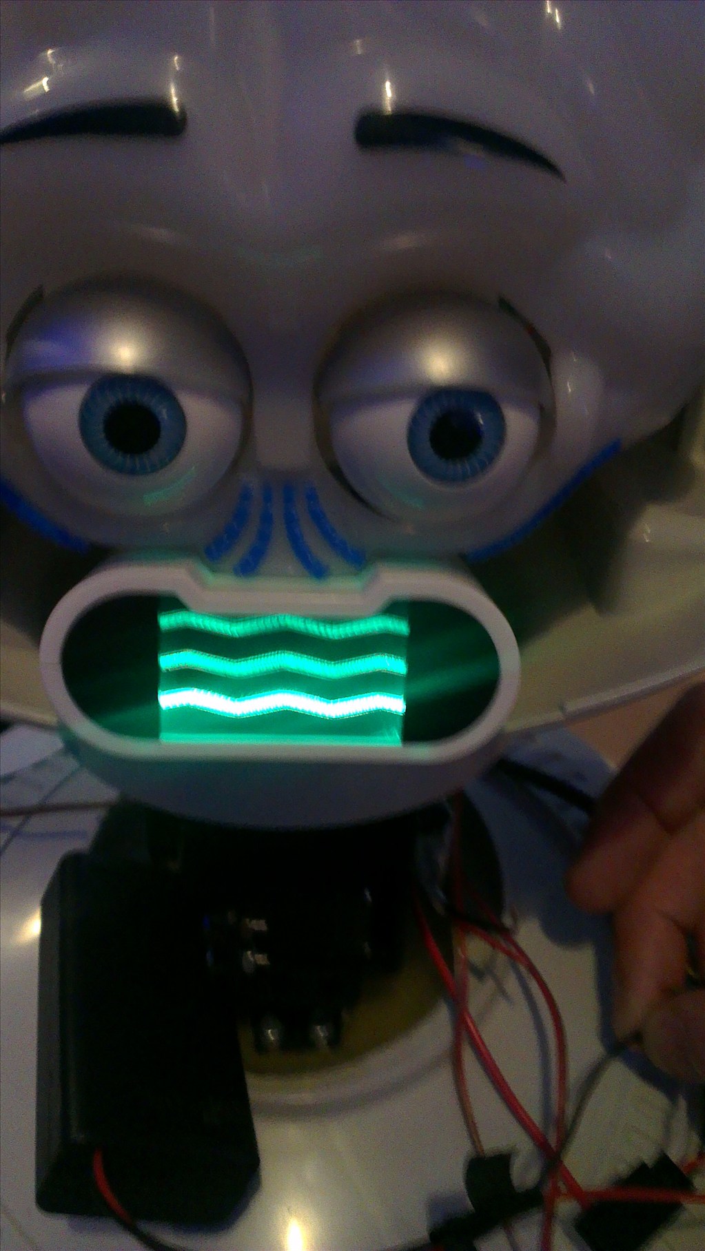
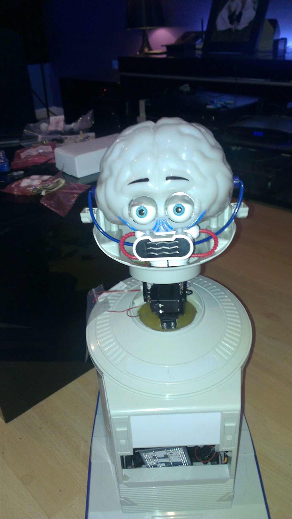
Then pop it in the mouth slot (after removing the old lamp) feeding the wires through the existing hole in to the head.

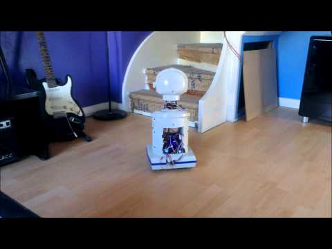
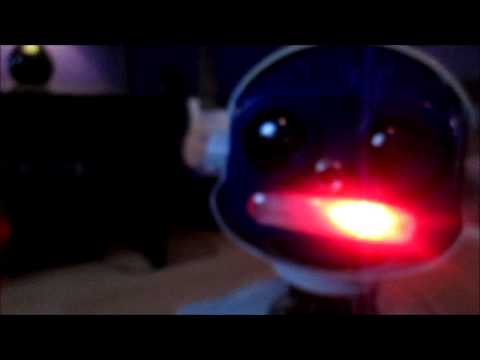
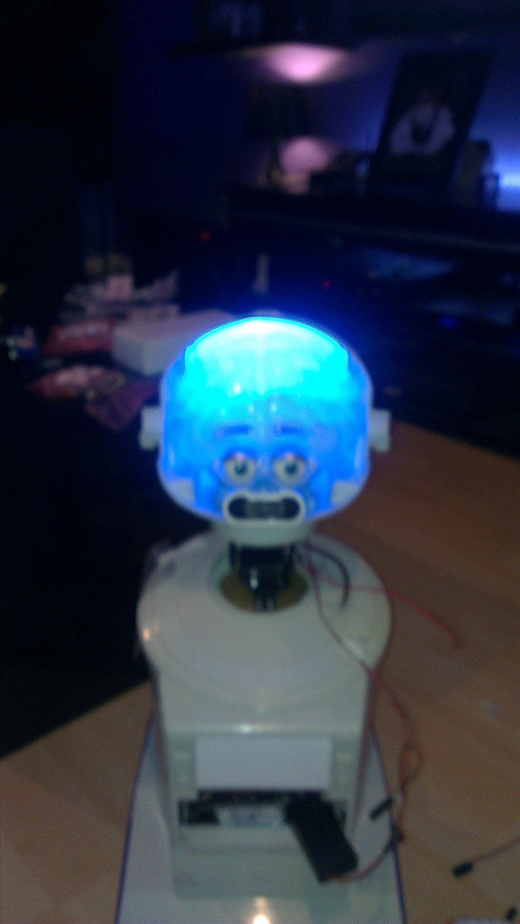
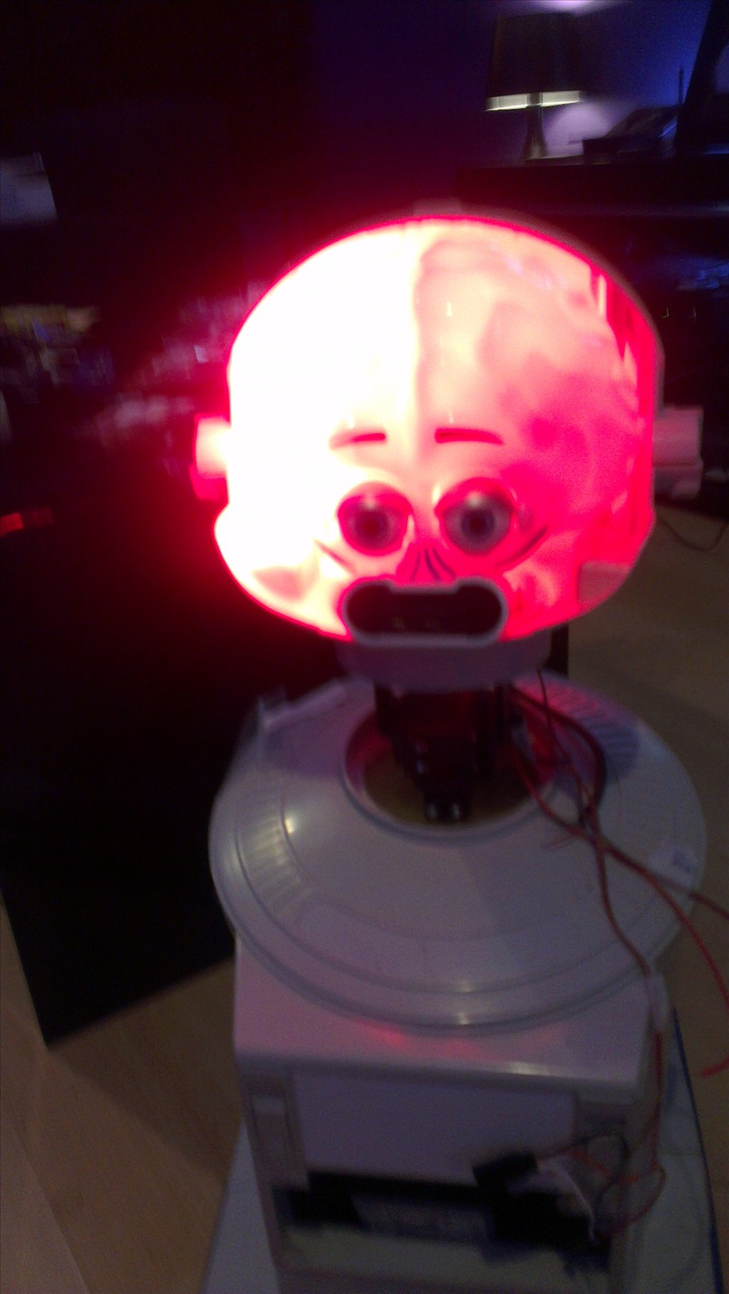
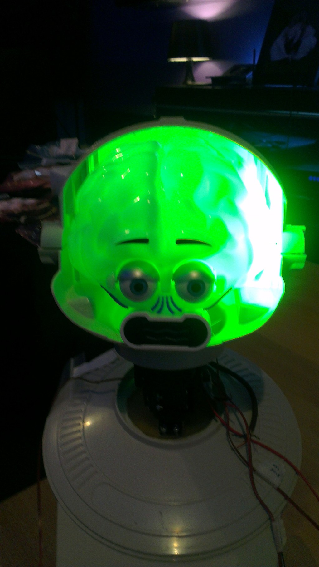
This still needs fixing in place permanently but not until after the painting is done.Put it all back together and voila
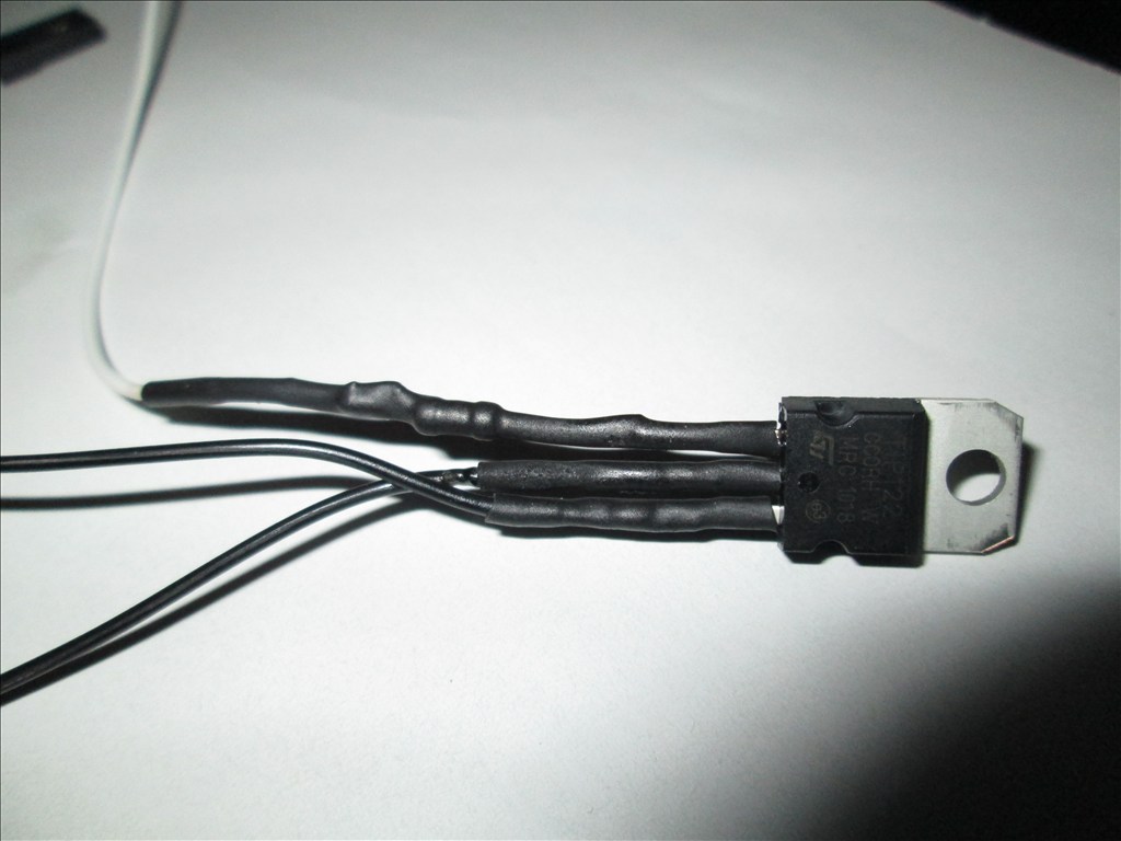
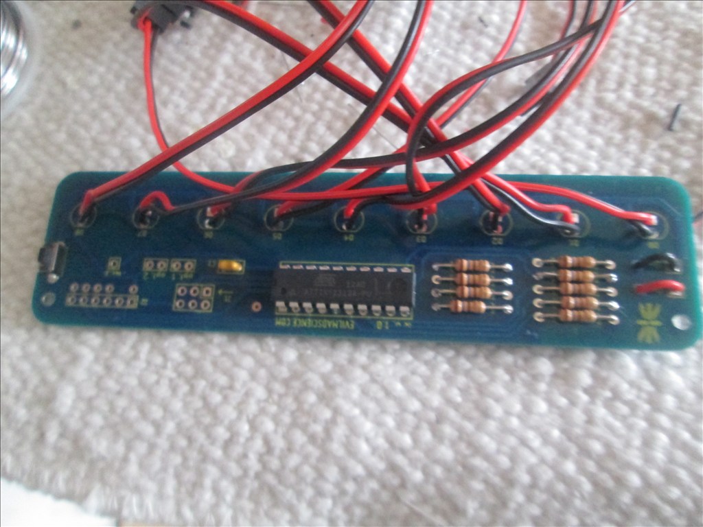
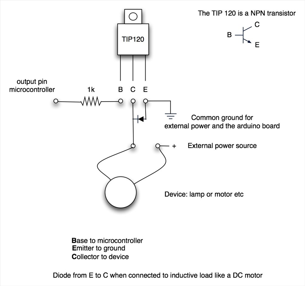
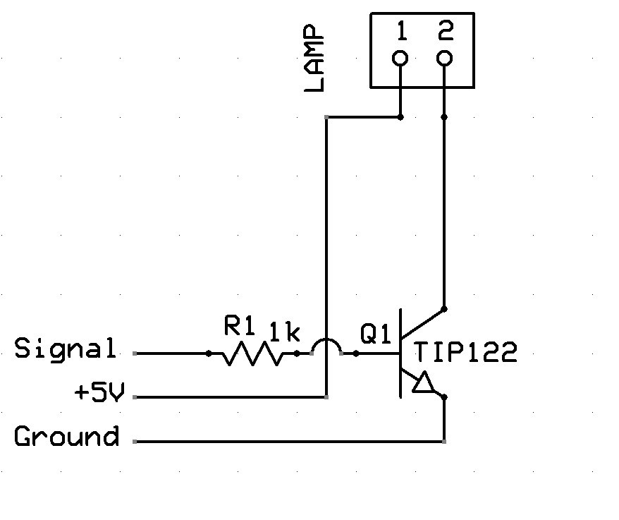
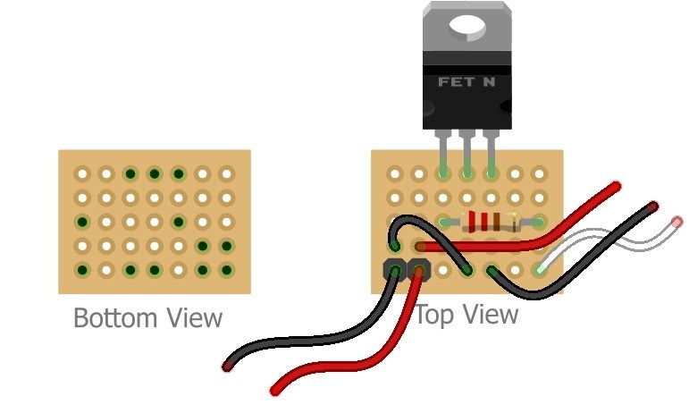
Unfortunately the Evil Mad Scientist Larson scanner runs on 3v, the EZB digital ports give out 5v. While there may be a 3.3v tap off on the EZB I don't plan to use it. I will be building a small 3.3v regulator circuit and placing it inline to take the 5V from the EZB down to 3.3v to power the scanner. A TIP122 circuit is used to turn it on and off. The mode select (hopefully) shouldn't need to be used.
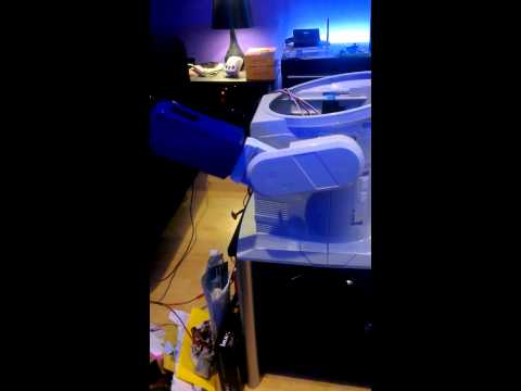
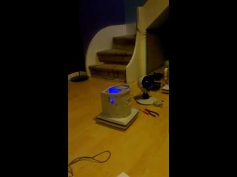
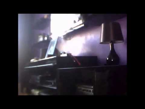
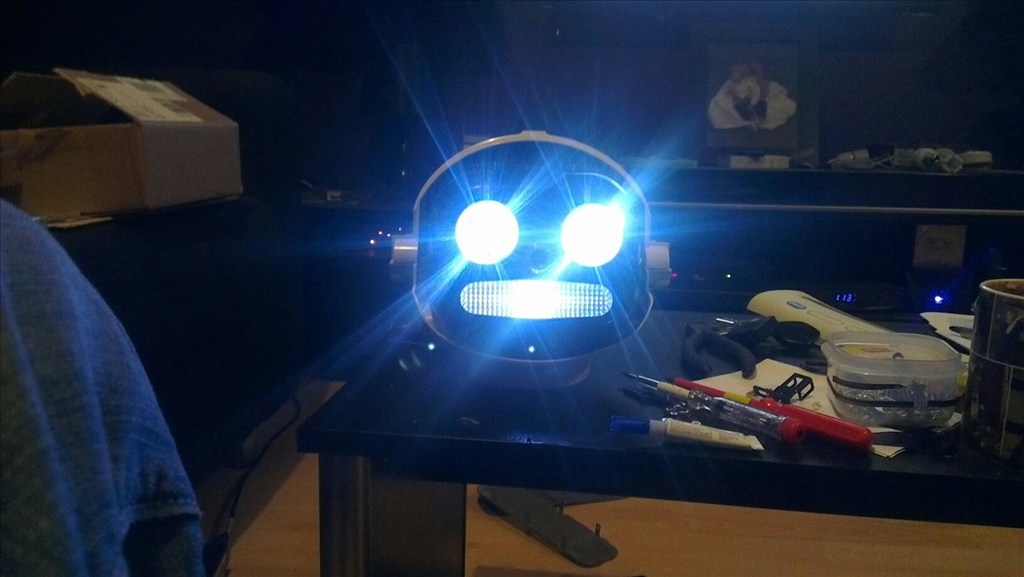
Since I wasn't expecting delivery of this for some time as I ordered from America I was unprepared for the voltage regulator so this will come later on. For testing purposes (and for the video) it was running from 2xAA batteries.
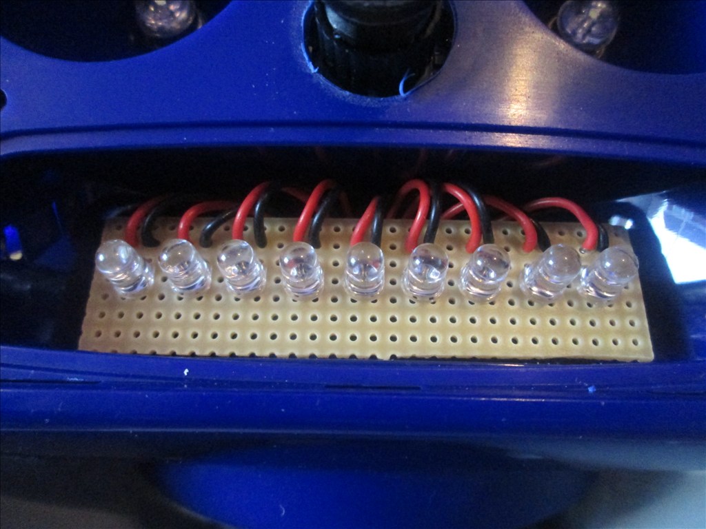
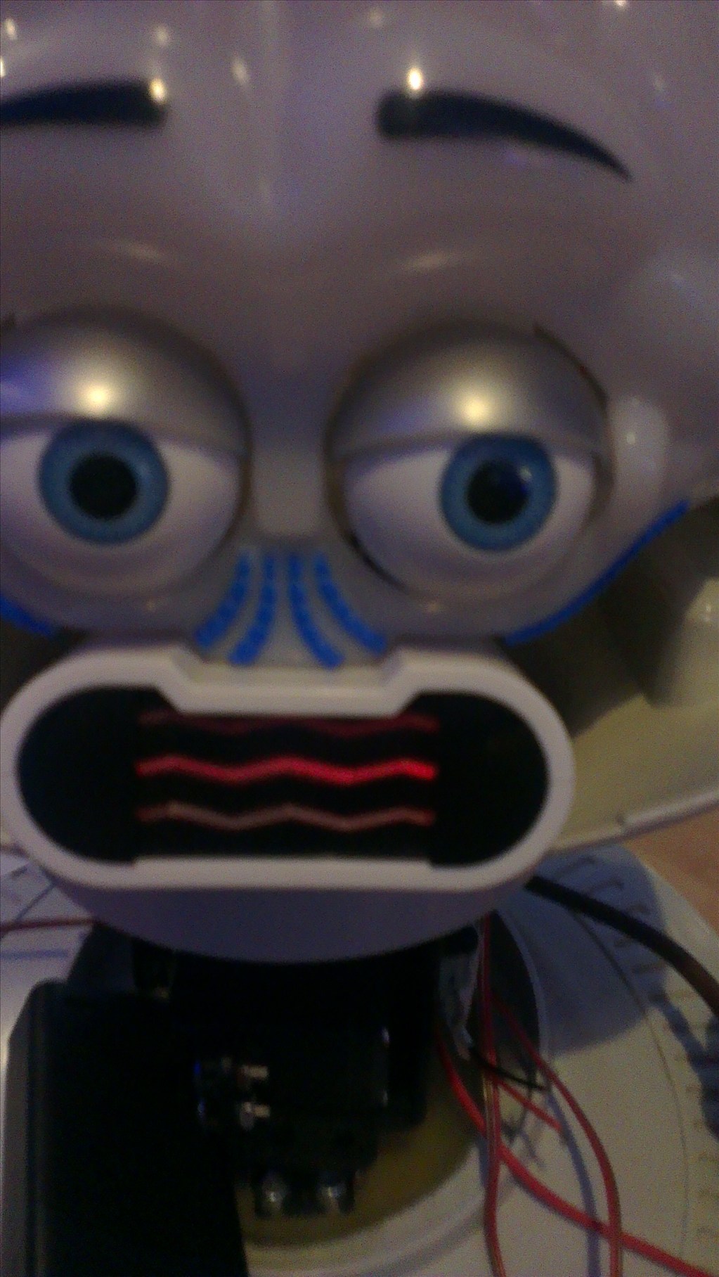
I'm not 100% sold on the red LEDs and may change them for blue or even white. Red still looks cool though and like it belongs so I may just leave it.
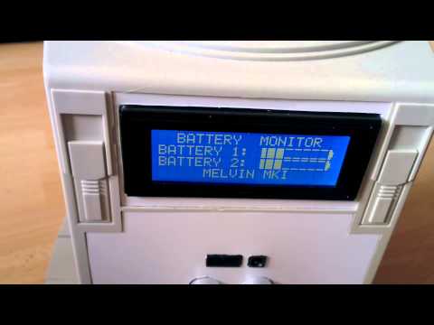
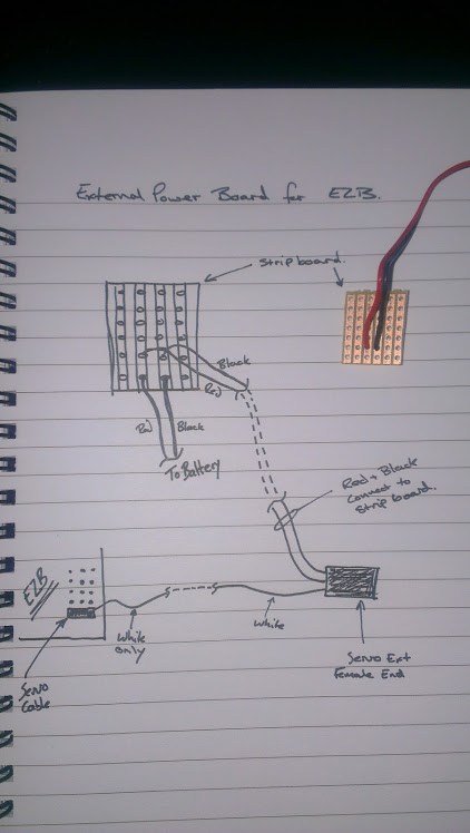
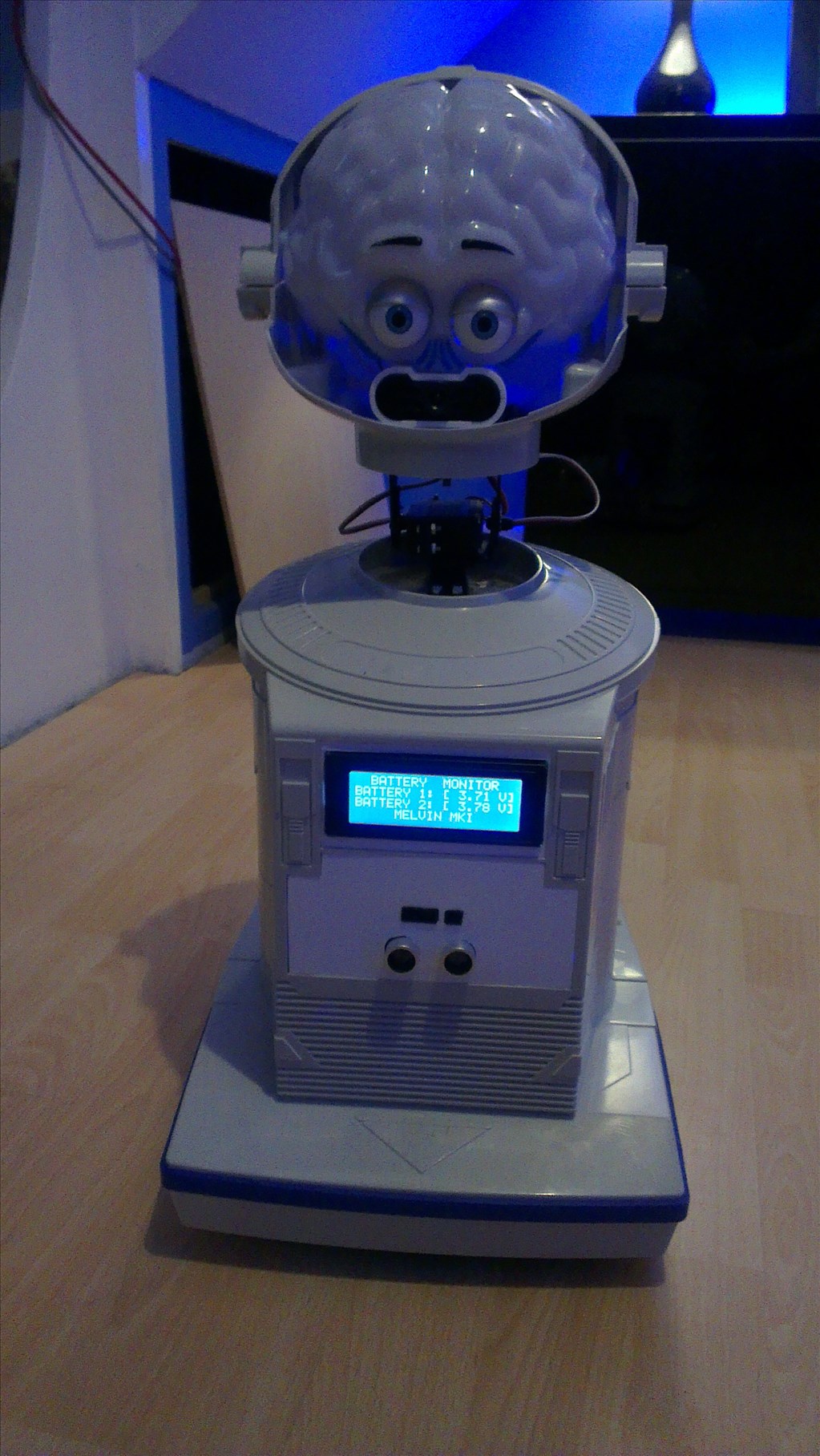
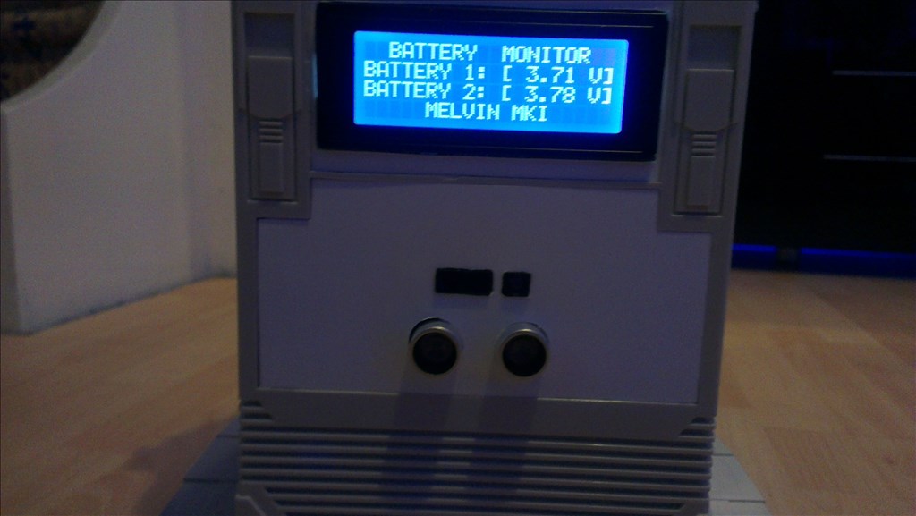
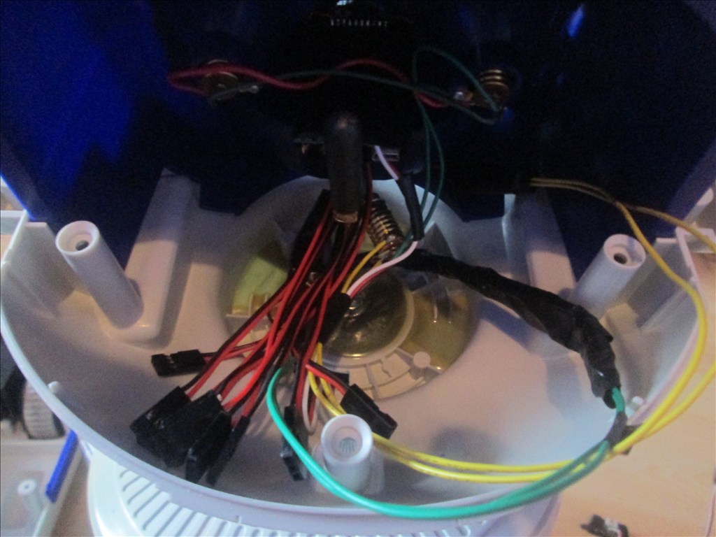
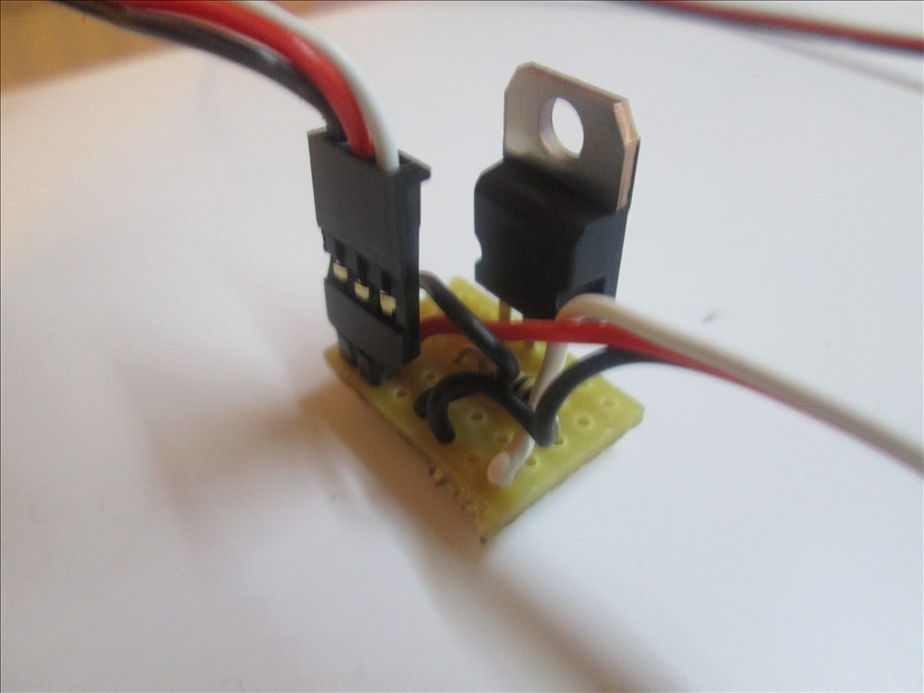
Something else on today's list (which I actually did before the Larson scanner above) is the LiPo battery monitor.
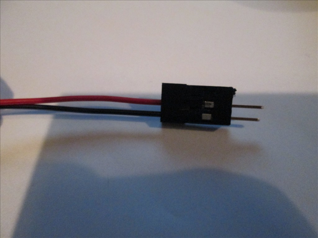
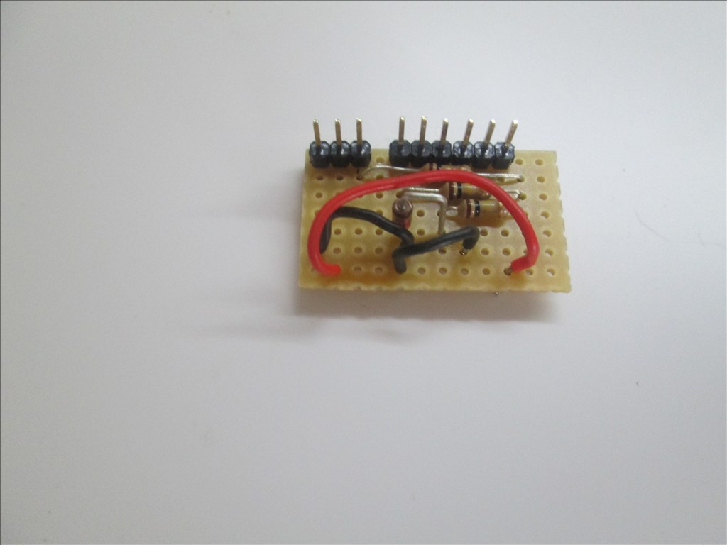
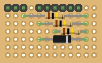
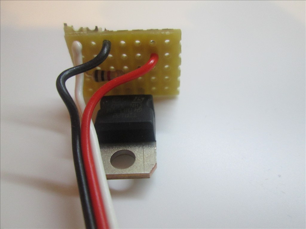
Full instructions on how it's made will follow when I have tested it, tidied up the schematics and have the time to upload the photos. But for now, here is the finished product waiting to be fitted (and tested of course).
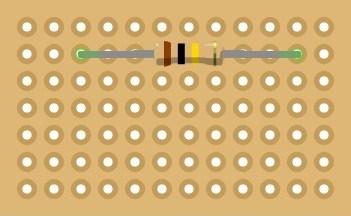
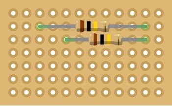
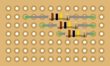
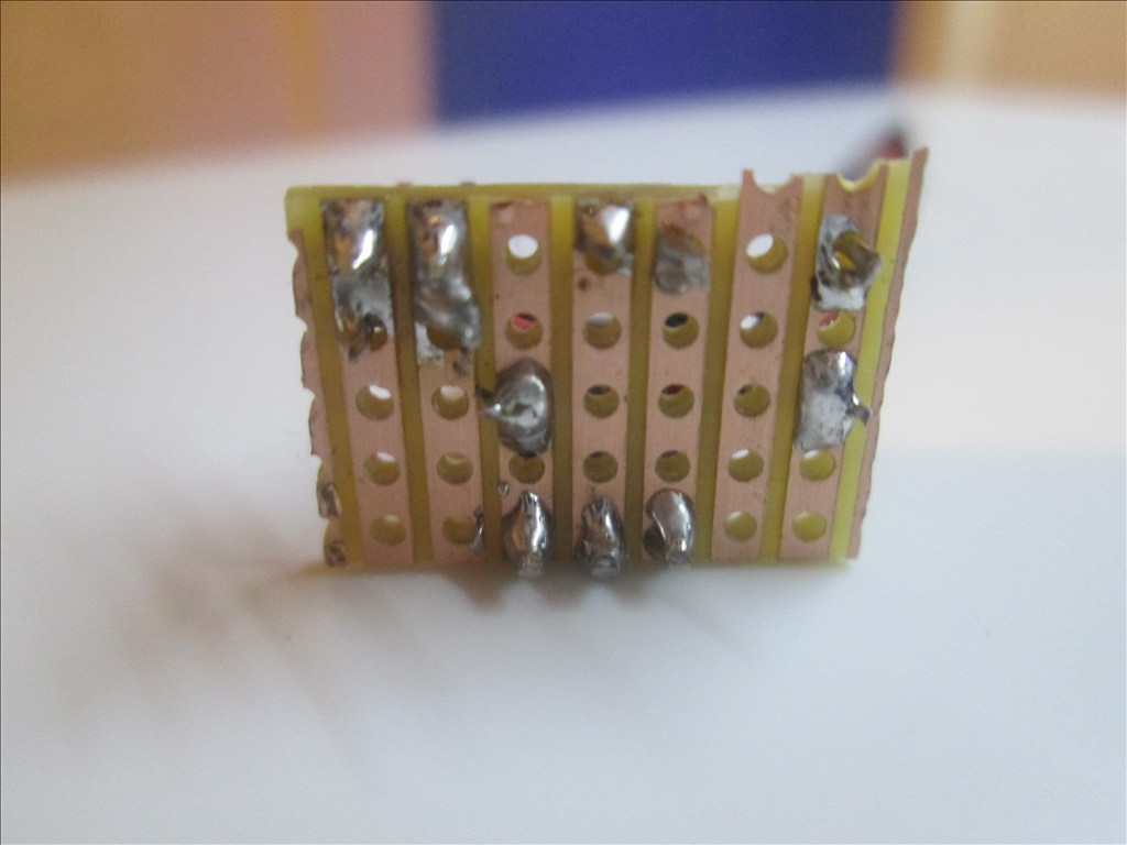
From this:
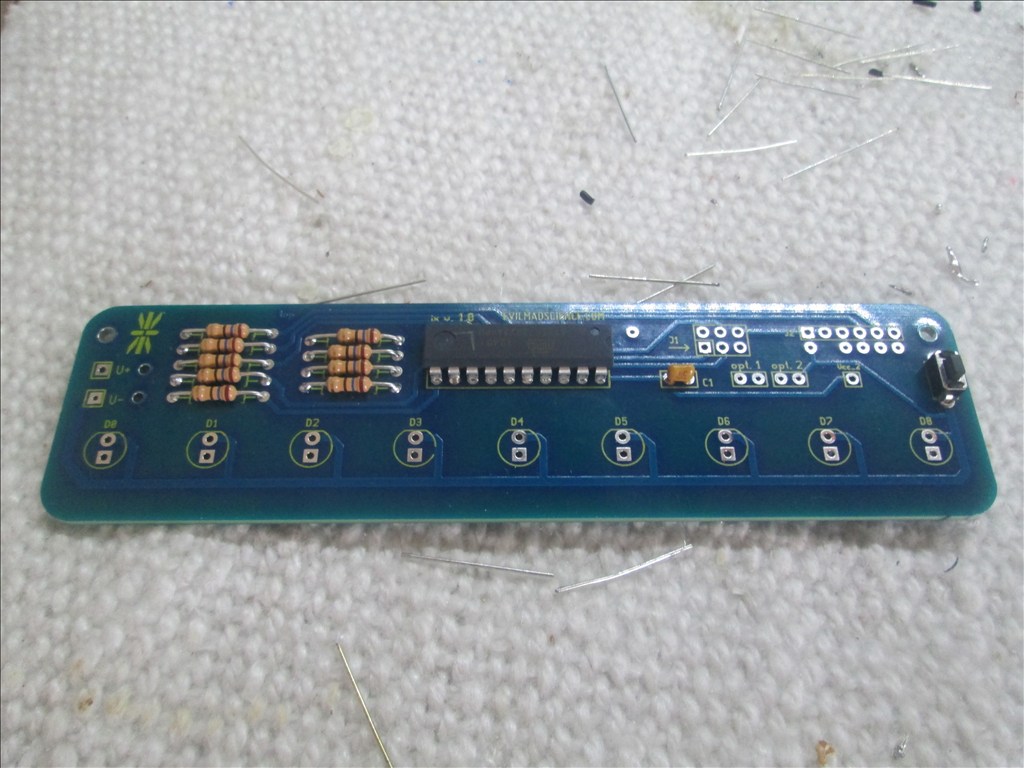
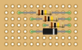
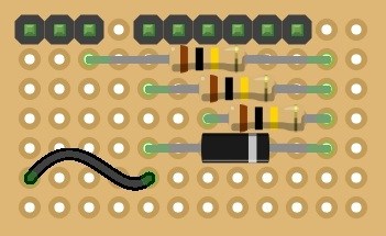
To this:

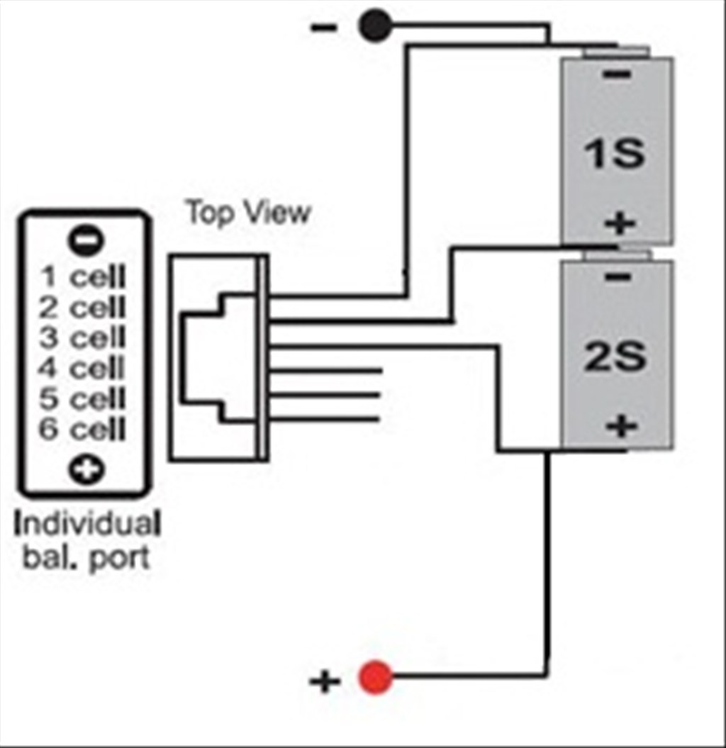
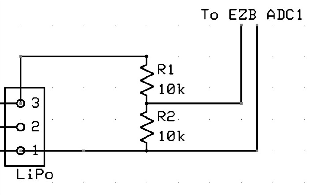
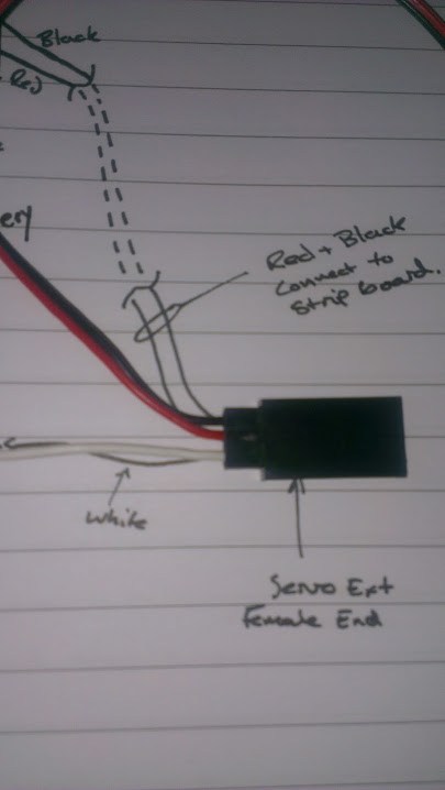
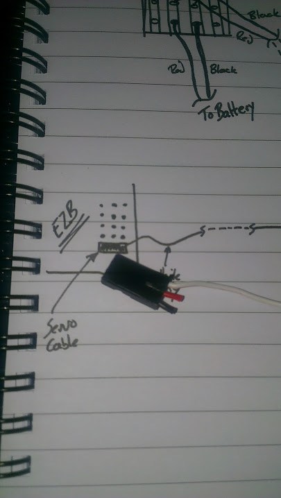
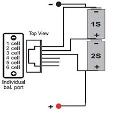
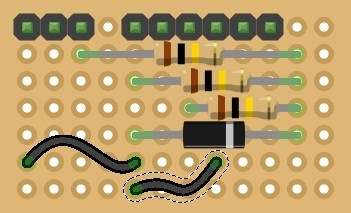
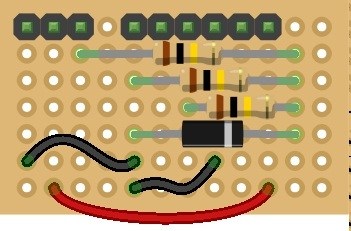
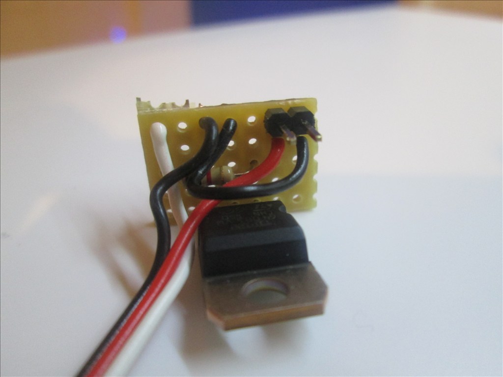
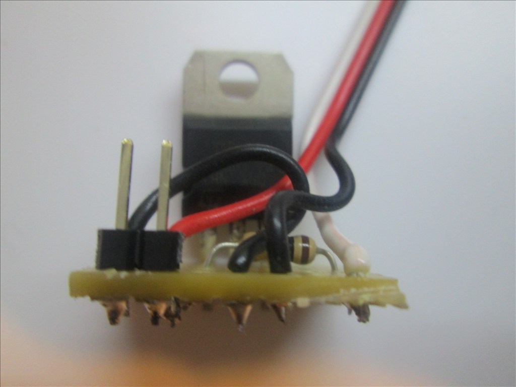
I'll probably shorten the red jumper wire, it's a little too long and I'm not happy with it (yes, I am that picky! Everything needs the correct colour wires, correct way around even when it doesn't matter... nothing bugs me more than seeing 2 resistors next to each other but each a different way round, or someone using the wrong coloured wire!)Simple design and removable. The 2S balance plug connects on to the 3 pin header on the left, two servo extension cables (plug to plug type) or servo plug to pretty much any 3 pin JST connector with 0.1" spacing fit on the other two 3 pin headers. They connect to the ADC ports on the EZB and a script monitors the voltage levels, warns of problems (over voltage, under voltage, low voltage etc.)
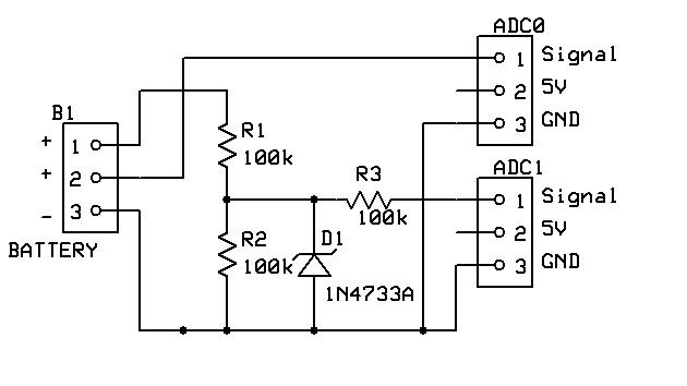
Basically, it's a voltage divider with over voltage protection which measures the voltage of both cells (full charge of 8.4v hence the divider), combined with a pass through for cell 2 (full charge of 4.1v), the script then calculates cell 1's voltage by subtracting cell 2's voltage from the overall voltage thus leaving cell 1's voltage.
As mentioned, full tutorial including schematics and script to follow when I have more time and have tested it.
Thanks Rich for sharing your project, this scanner led "The Evil Mad Scientist" is great, by the way I discovered the store did not know her, and lipo voltage divider for two elements is a good work, I think I will add to my list pending a scanner parts and components led to the voltage divider, good job, sure many others benefit from your project.
If anyone else plans to use the Larson scanner with their EZB you needn't use a voltage regulator (like I planned above).
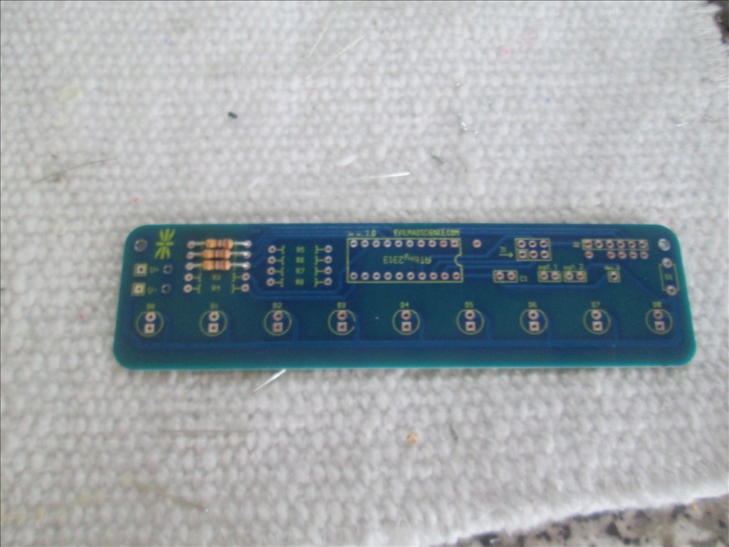
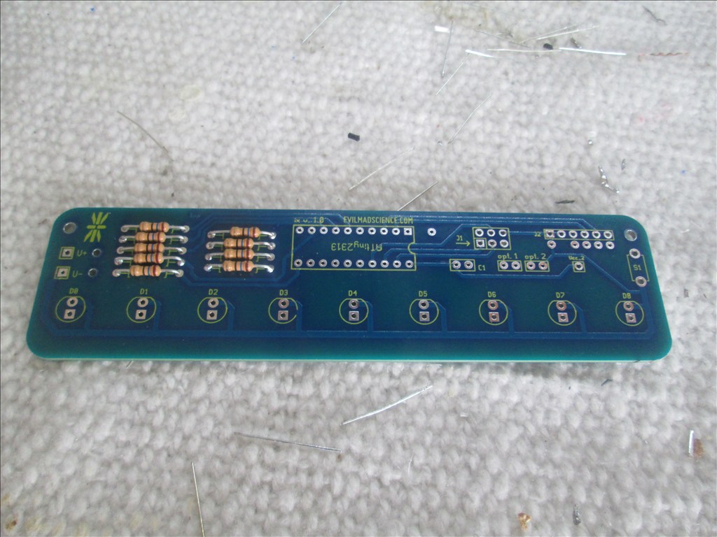
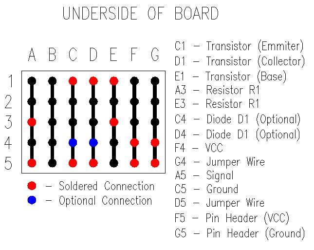
Rather than adding in a voltage regulator for the 5v to 3v all that needs to be done is for the resistors to be replaced. Since the ATTiny2313 can accept up to 5.5v it shouldn't be a problem at all.
LED specs are; Forward Voltage 2.1v Forward Current 30mA
Which basically means replace the 33ohm resistors for 100ohm according to my calculations.
looks like you did agood job in the circuit RICH on mine using bar graph display circuit to work with sound not happy about beening in china,but i guess work comes first before FUN
BLue led wont be as good as RED ,since the head is blue Unless you going to repaint him
also see you added the idea i had for the ZENER ,good practice to have protection and i forgot also if the battery is wired wrong it saves the circuit,from what i remembered Havent tested the theory yet
Whats the ATTiny2313 for,does the larson project use 4017 decade counter,(one of my favorate chips )
ALSO there is a way for the larson project to move with sound,i made the design awhile back for my work,might have to redesign it a little so not the using the work circuit
I know i cant use any of there designs for profit,but willask if i can use it for my home project