


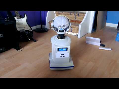


Now I have the EZ-B kit and the Hearoid it's time to start my Showcase thread.
I still haven't decided on a name for him yet, all suggestions are welcome.
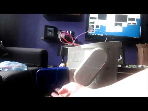
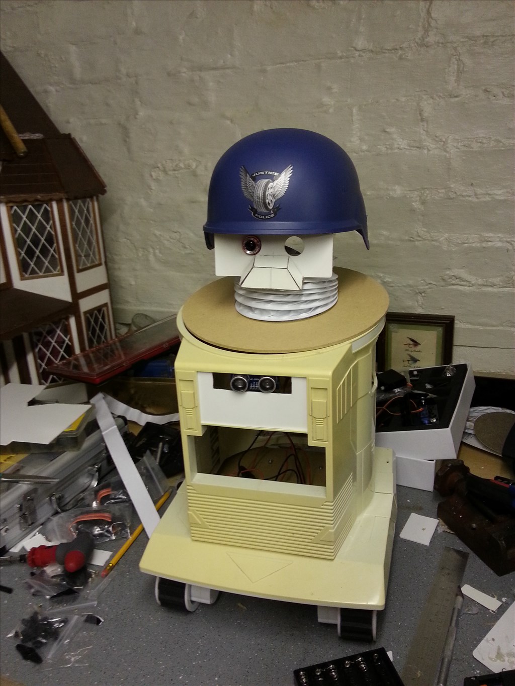
I won this robot on ebay weeks ago, for the past 2 weeks he has been waiting for me to collect him...
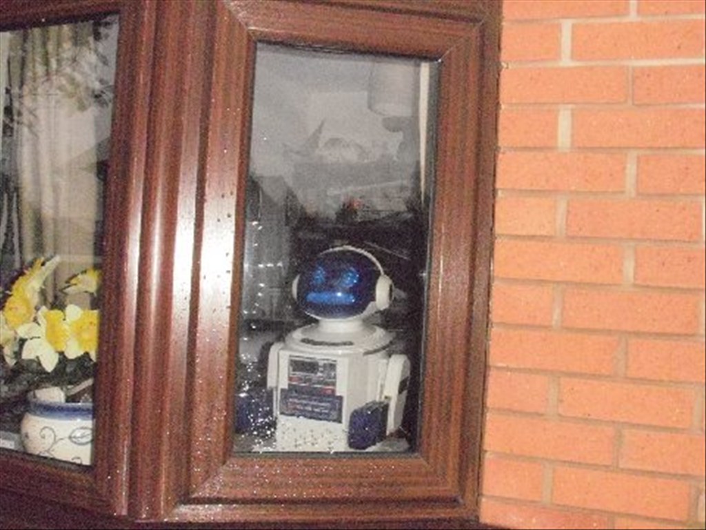
Today was the day, a road trip to pick him up and bring him back to his new home...
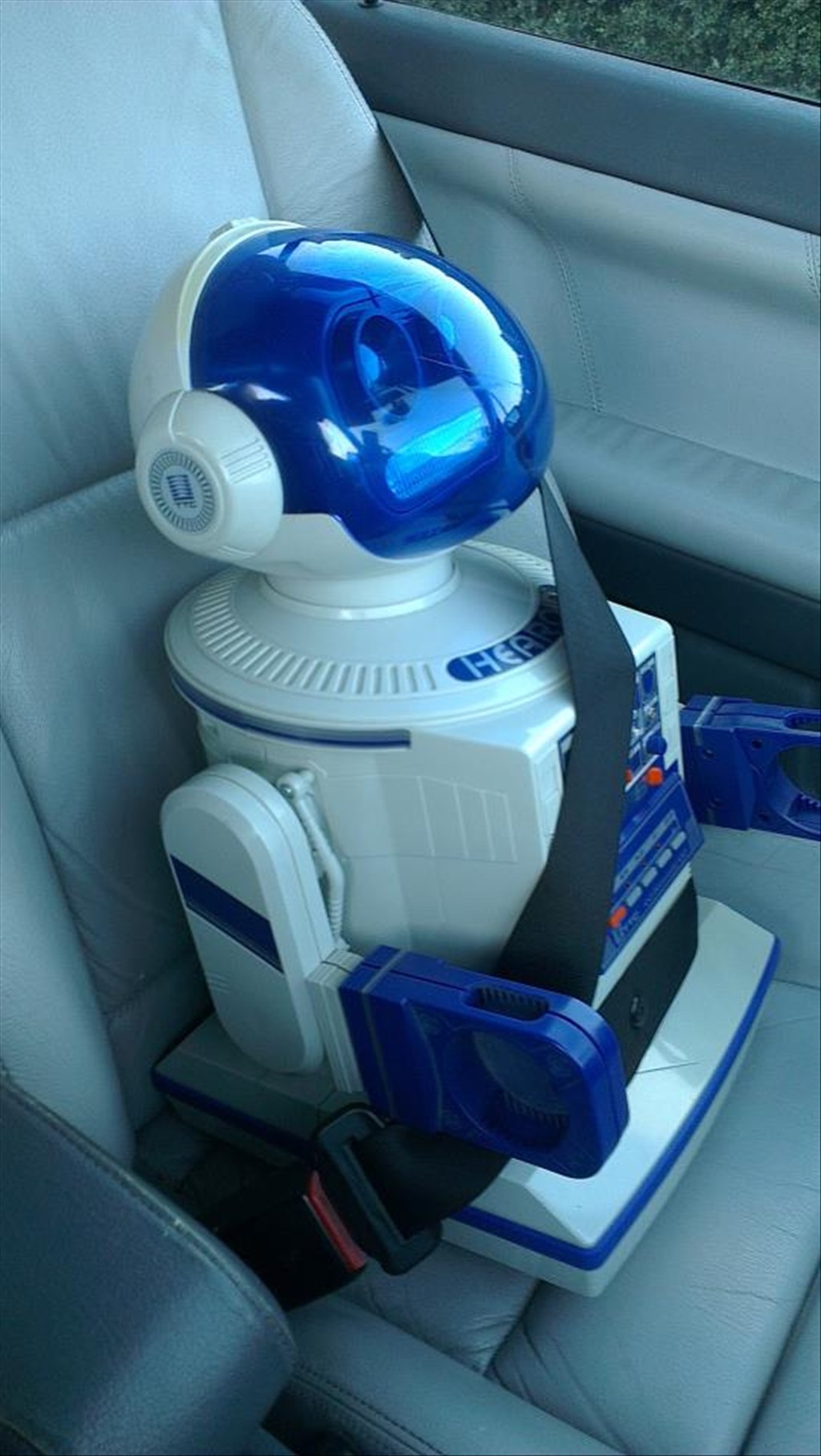
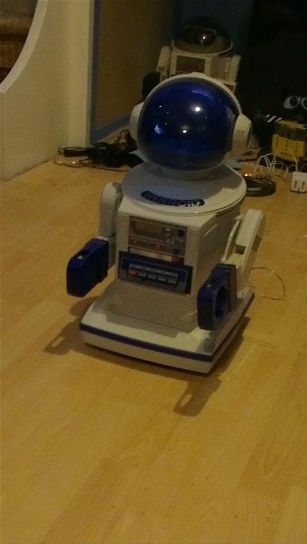
In his new home (with Omnibot and Wall-e in the background totally unaware they are next in line to be opened up)
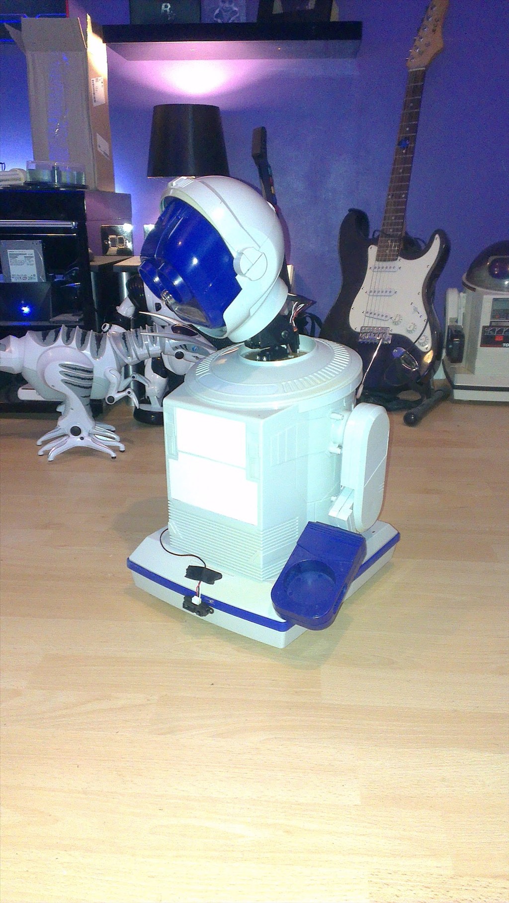
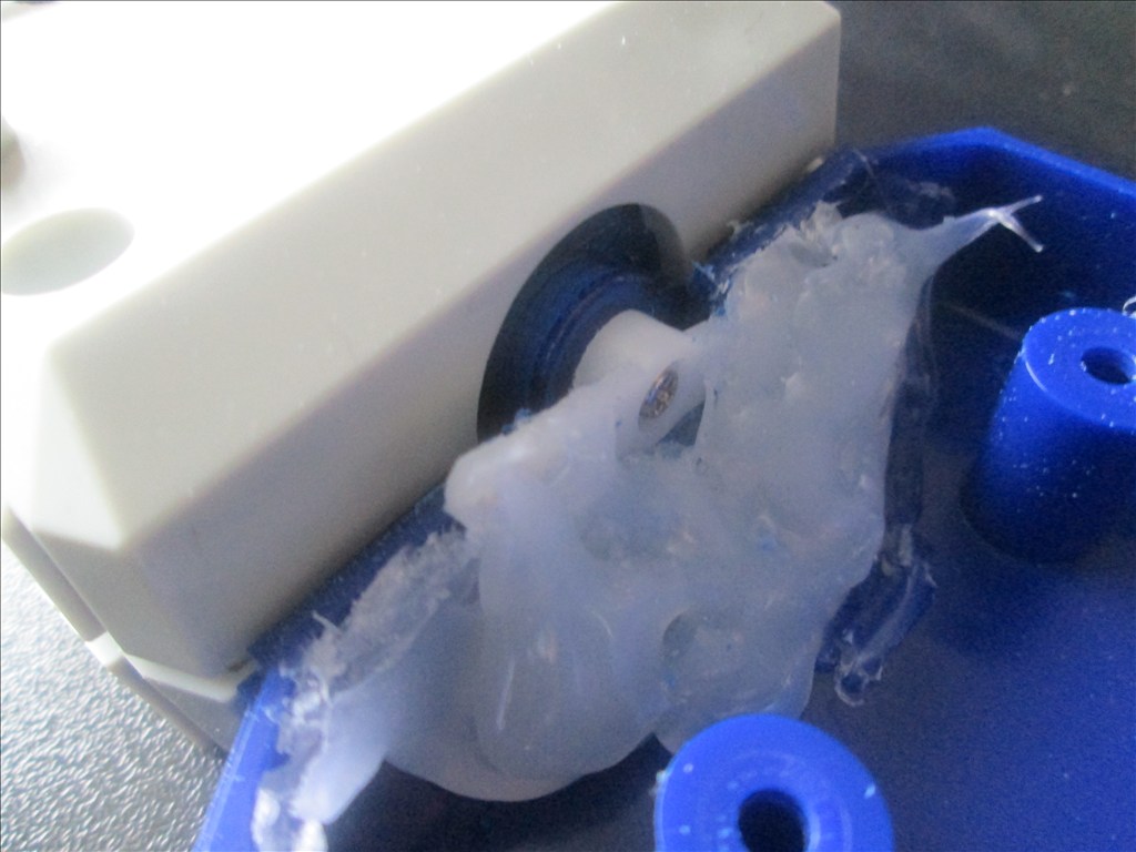
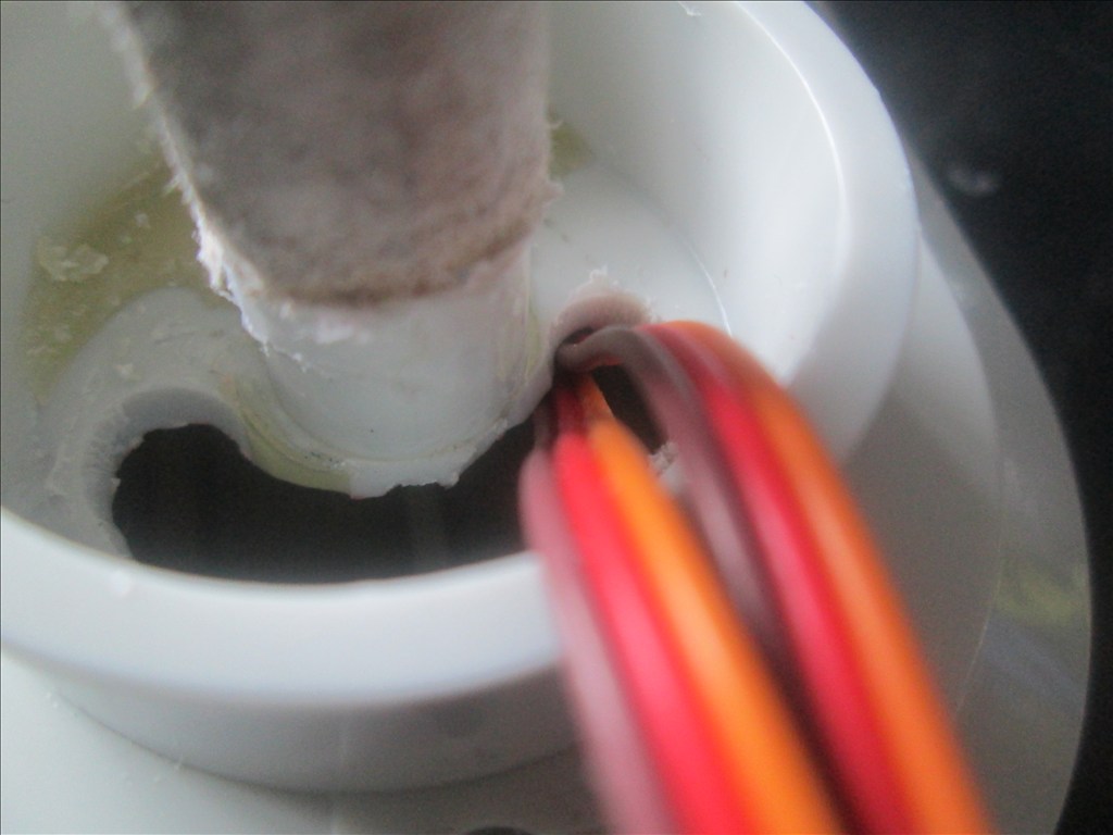
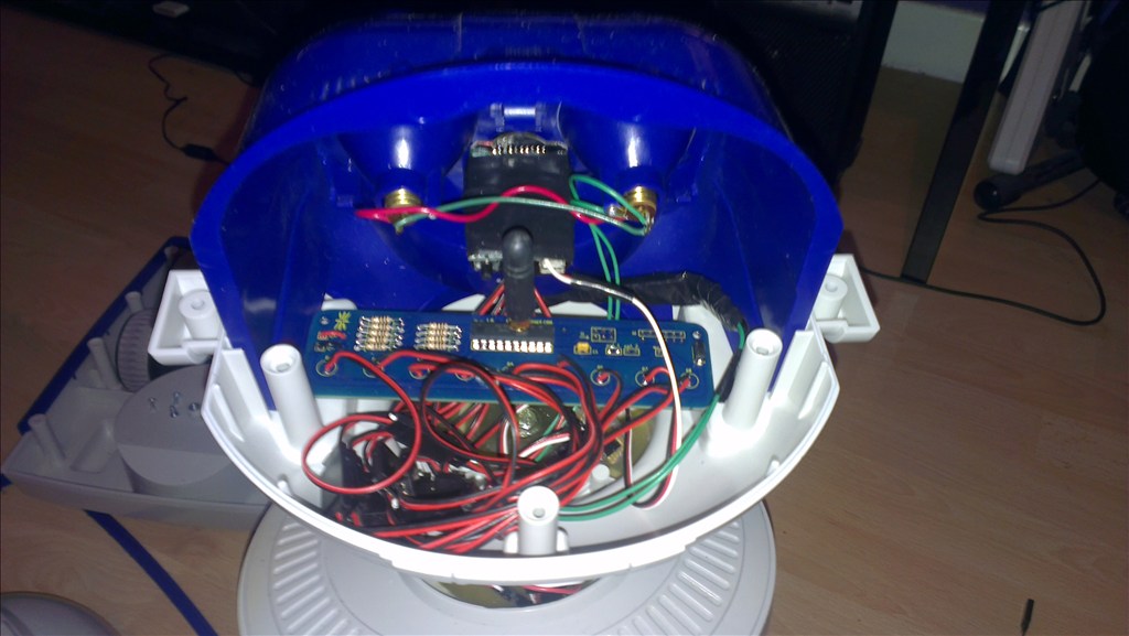
It wasn't long before this happened...
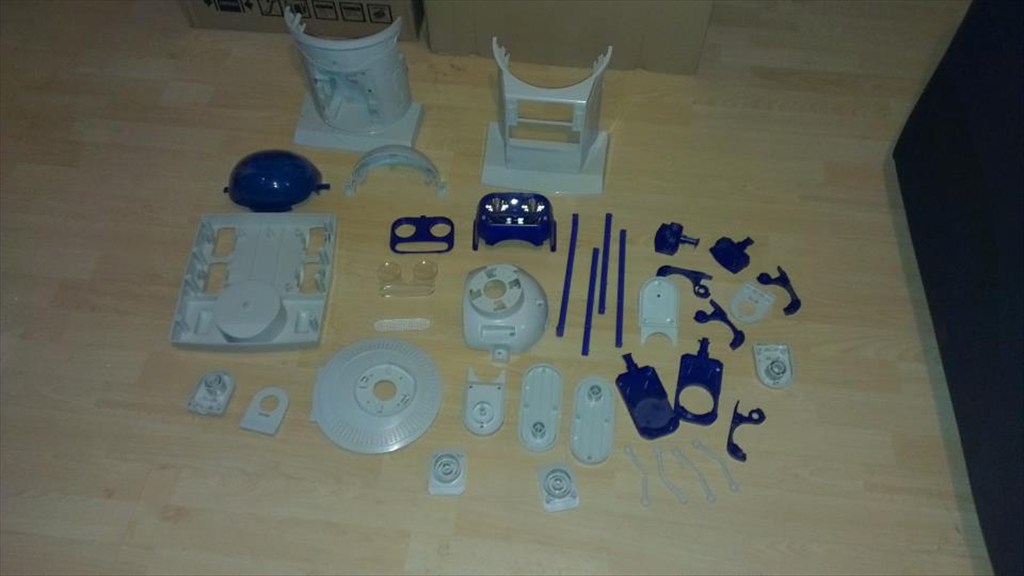
Now waiting to go in the dishwasher to get nice and clean.
The plan is to make him autonomous, running 24/7 (except for when he knows to go charge himself up) but will also be adding in the various image tracking options.
The only other slight modifications to be made to him are to convert the head to tilt & pan which will involve having to give him a small neck.
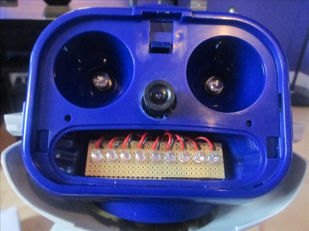
The head will include the camera. I haven't yet decided to fit it in one of his eyes or to make it his nose. The issue to overcome with this is the blue tint on the bubble head. The mouth will have a light or some lights in which flicker when he speaks.
The arms will be given some life with servos at the shoulder joints and the elbows provided I can get them to fit in there nicely.
Ultrasonic sensor will be in his chest, probably on a servo to give a wider view.
Original drive wheels and gearbox seem to be in very good shape so will plan to reuse those and just replace the existing motors for the modified servos if they can manage the task.
Speaker and microphone will be in the original positions - if it's not broke why fix it?
Not too big a project but enough to give me a test, help me learn and bring an old robot back to life.
Other robots from Synthiam community
51M0n76's Meet Arnie
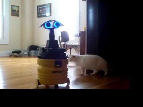
Csa459's Wet And Dry Vac Demo Video

Let me be the first to say thanks for posting this thread. I really like that model robot and you got a nice one! He has a really cool looking face. I am looking forward to seeing what ideas you come up with and how you impliment them. Good luck, have fun and we will be watching!
I love this style robot and the rad robots too. If your going to run him for long periods then a larger battery is in order. If you stay with 6 volts power sonic and other brands make a 6 volt battery that you can easily fit two of in the bottom of your robots torso. Two 6 volt 12ah batteries means 24ah of capacity.given the original battery powered the omnibot for almost an hour you could have 2 to 4 hours constant run time between charges . Also I've seen great success from other members telling the robot to follow a glyph and getting it to dock like a roomba face first.
The battery is what I'm currently looking in to although it's the last item on the shopping list - for now my ez-b is powered by a mains transformer for testing everything. Once I've got the robot back together with everything else in there I'll have a better idea of the space available for the battery/batteries but it looks like there is going to be more than enough space for them.
The batteries and charging station will be the last thing I look at though. I'm more interested in getting the robot back together, looking like new and moving around again.
My biggest problem at the moment is the face. The blue tinted visor is no good if I want to use colour tracking as the camera will be behind that. I need to either find a Robbie Sr. head (if it's the same size which I believe it is?) and use the visor from that, see how it looks without the visor or attempt to mould my own which may be beyond me.
Besides, the blue visor is scratched and washing it has showed those scratches up even more. I may try to polish them out if it's possible but I have limited experience with that.
I've ordered a mini tilt/pan bracket, it uses mini servos but hopefully they will be powerful enough to move the head, if not then I'll find another way of doing it.
Have rewired the camera from the EZ-B kit to be powered and switched by the EZ-B, although my soldering iron was playing up and only getting hot enough to just about melt the solder so I'll have to redo it. It works but I'm not happy with the soldering. I think it's time I invest in a better soldering iron (mine is just a cheap gas powered thing).
Half of the robot is now clean, the other half is in the dishwasher being cleaned now (small dishwasher).
And I've got a bunch of servos, mini servos, cables etc. on order now too so plenty to play with.
Welcome to EZ-B! I love the Hearoid, but could not find one so I did the omnibot. Here is a link to my build - it may give you some ideas.
Bob was completed and now I've gone back into him to make Gunslinger Bob. Good luck with your build!
@Bret your project is going to be a great help to me as are all of the Omni projects, the body is the exact same so other than my pan/tilt head modification which I think I have figured out.
The Hearoid wasn't my first choice, the Omni was. But when I bought my Omni (after over 25 years of wanting one) he was in such good condition I didn't want to take him apart. Looked for another Omni to modify and come across the Hearoid... I love the head, it just makes him look that much more human like, which is why I really want to figure out a way to make the blue tinted visor clear (well, either make a clear one or find a Robbie with a good condition one).
I love your idea of the EZ-B in the cassette drawer, that's an idea I may be looking at "borrowing"...
I'm currently trying to reuse the original drive but replace the motors for modified servos... I'm thinking opting for a HBridge would be the easier option... But I haven't given up yet...
Rich email me real quick [email protected]
@Josh - head swap?
Maybe so , trades are great
Right then, so after messing with the original Hearoid/Omnibot drive trying to figure a way to run it with modified servos I gave up, it'll be easier to use the existing motors as they work perfectly fine.
But, how would you guys suggest going about this? Is the TB6612FNG H-Bridge the best option?
That little controller looks OK to me, a little more hands on with soldering (not a bad thing for some ) but a good price and newer, more efficient tech then the L298N based 2.5A. I would slap a heat sink on it even if it seems already rated higher without then the L298N with.
If you are OK with modding the face dome, I would consider drilling a small hole front and center for the camera lens to peek out of (also allows easy focus adjustment if ever necessary). Remove the cameras shell and set up the rest of the head space for the EZ-B and whatnot. Their visible circuitry, LED's blinking and such behind the blue tint would look like the brain it is @Josh did a great mod making a mounting deck under the dome on his Squeegee bot that might work for you as well.
Soldering is not an issue for me, I prefer not to have to do it but I can do it very well - if my iron works like it should unlike yesterday (but that's because the tip is dirty and oxidised and I have no more cleaner left).
To be honest, I'd rather not drill through the dome. Ideally, although perhaps not realistically, I'd like everything like the camera, servos etc. to appear totally hidden on a quick glance but we will see what happens (the elbow servos will be the biggest challenge there). The possibility of swapping the blue for a clear dome is one which is very appealing but that all depends on availability, cost etc. - I've already spent far too much this weekend and I've barely started...
If the clear dome doesn't work out then he still looks pretty cool without the dome fitted, in fact it shows his face off a lot better without the dome and I'm starting to like that look a lot.
Heh, the expense never ends does it I like the idea of your stealth approach... and probably would have realized your goal if I had red your posts over again before offering an idea blush Actually I think a good stealth method shows a much higher degree of skill and planning anyhow... almost an art
A quick update while I am on here...
Currently I'm battling to get the head to pan and tilt. My pan/tilt bracket I bought wasn't up to the job of lifting his head at all, it wouldn't even hold his head. So I guess mini servos are out of the question. Just ordered a heavy duty bracket and servos but it's a bit bigger which will pose an issue when it comes to hiding it (I have ideas though but any others would be appreciated).
Still waiting for my servo extension cables to turn up, I have 2 lots on order from 2 different places and still none have shown up which means I can't wire the H-Bridge and get the base all wired up and ready to go.
So at the moment, it's still in bits and looks like I have made no progress at all, which kinda kills the motivation. Although I have planned everything, cleaned it, currently waiting for the fibre glass to set where holes have been filled... the boring prep stuff - I just want something that moves now though!..
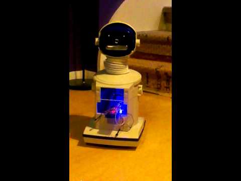
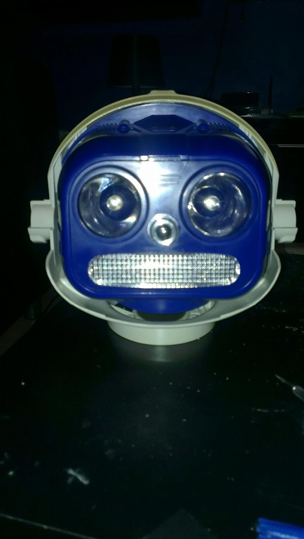
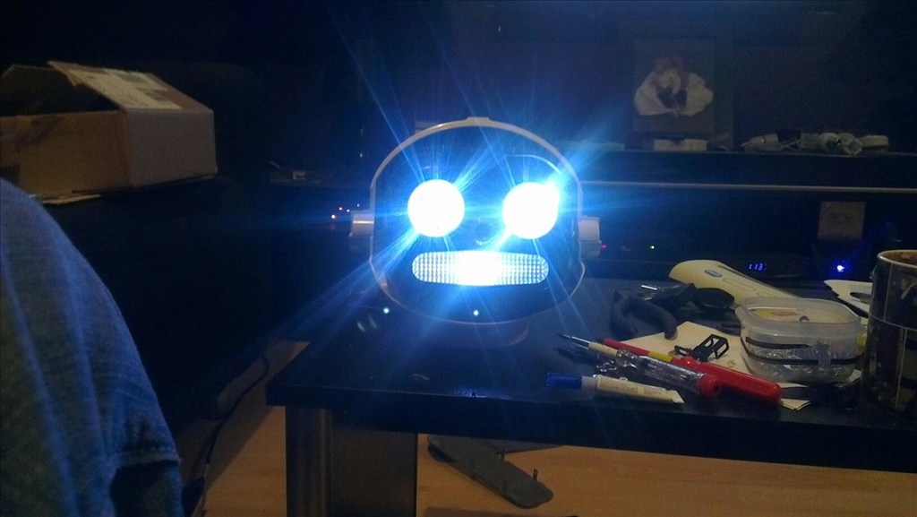
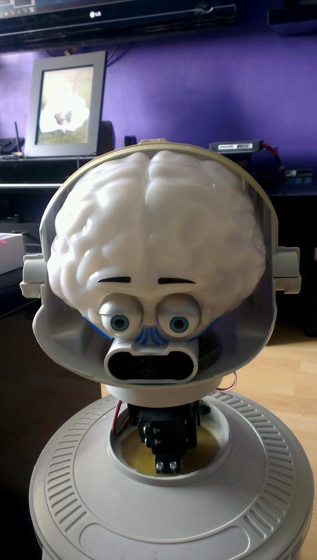
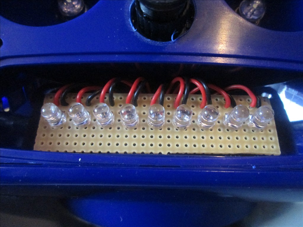
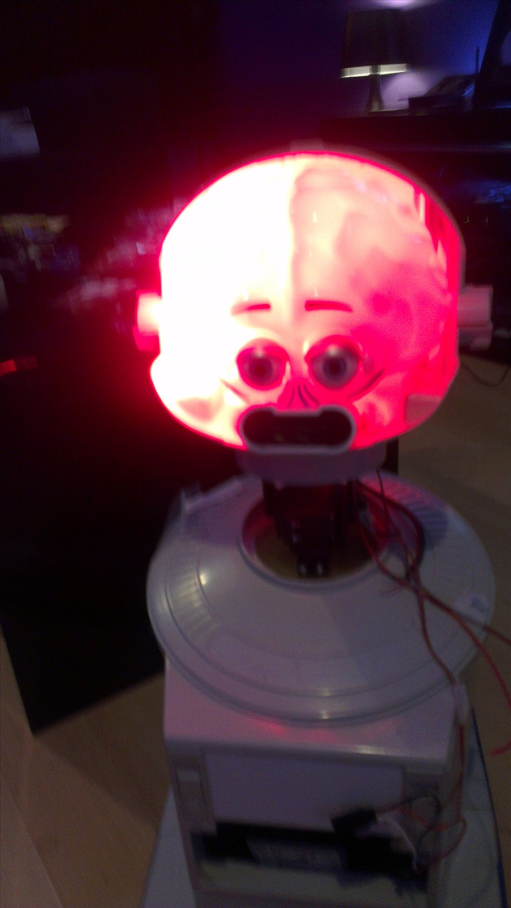
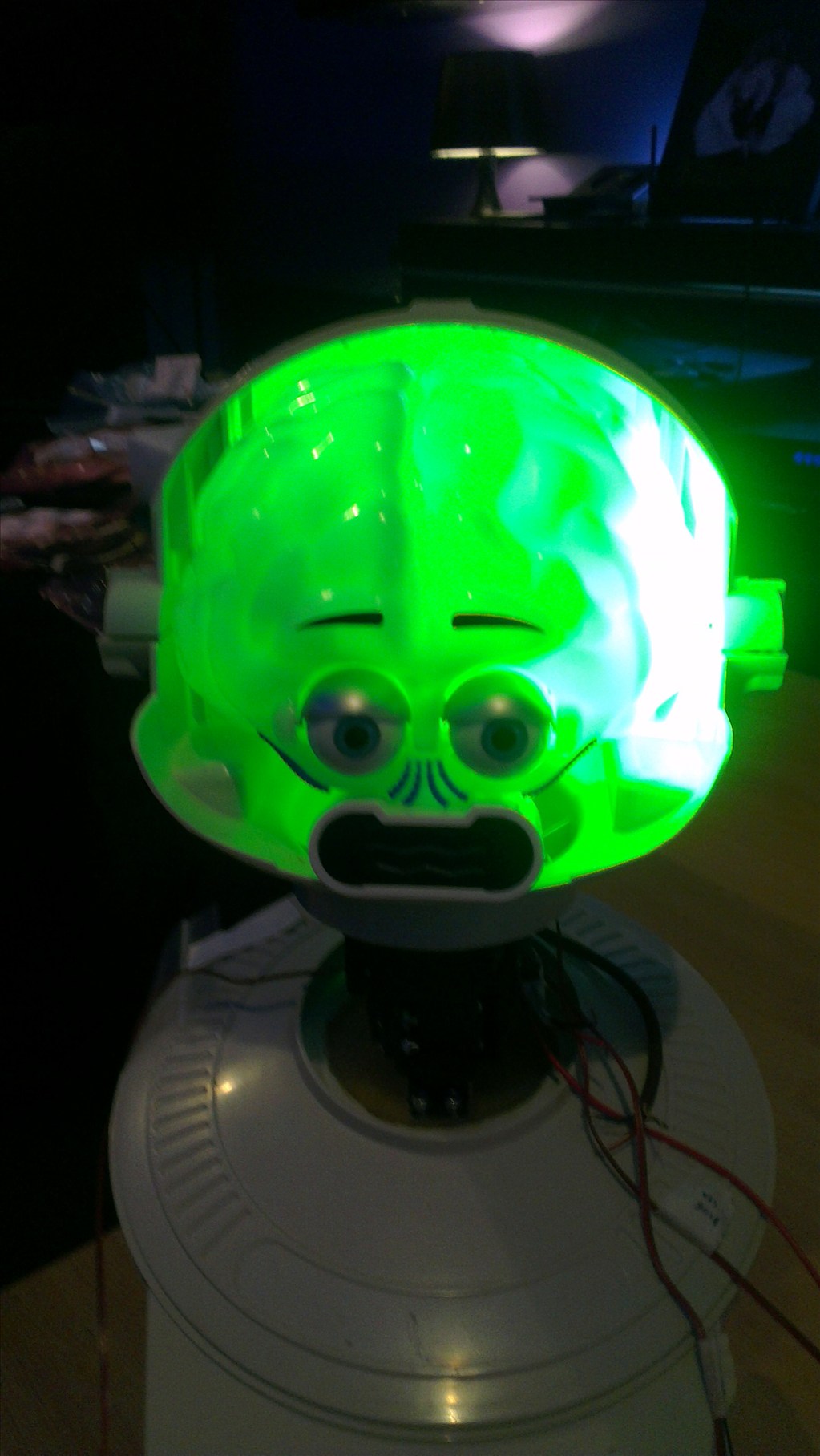
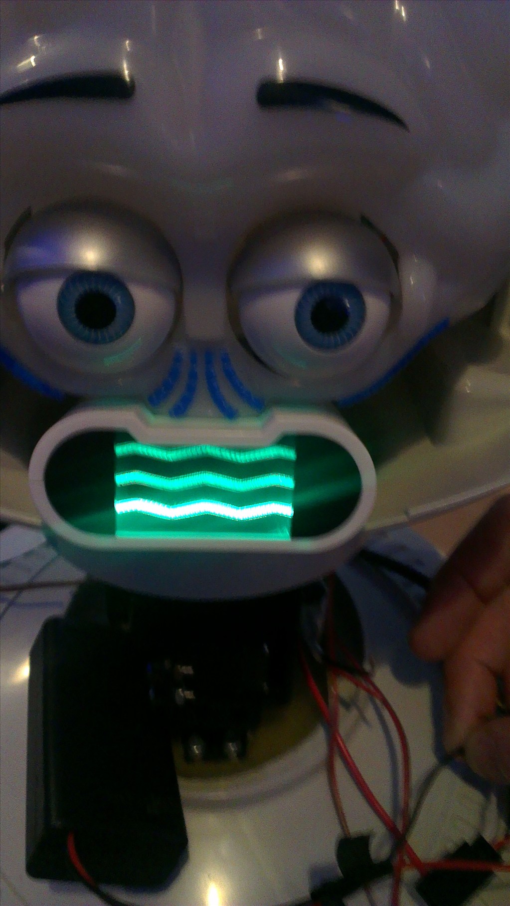
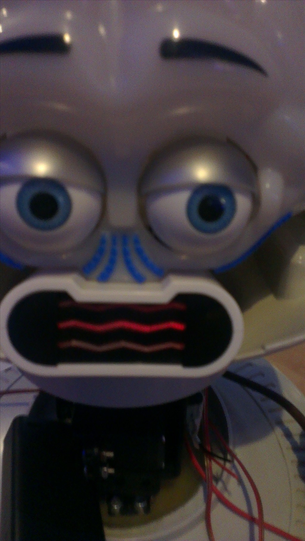
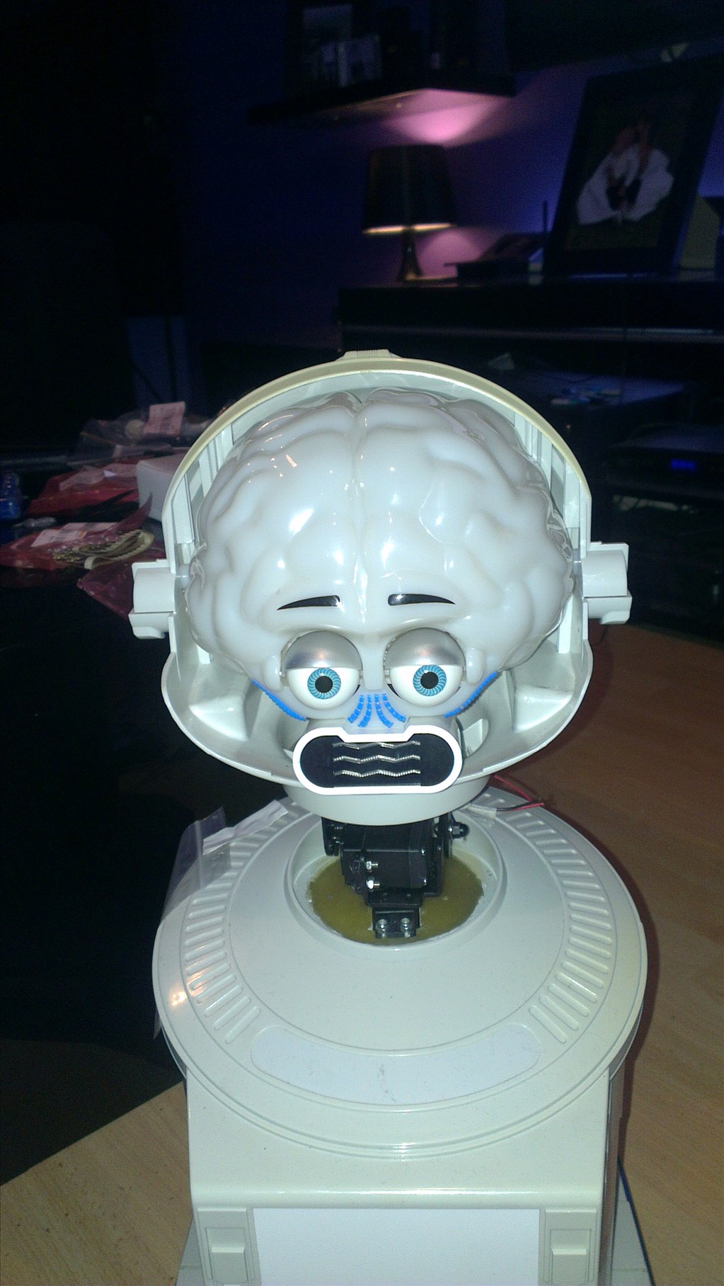
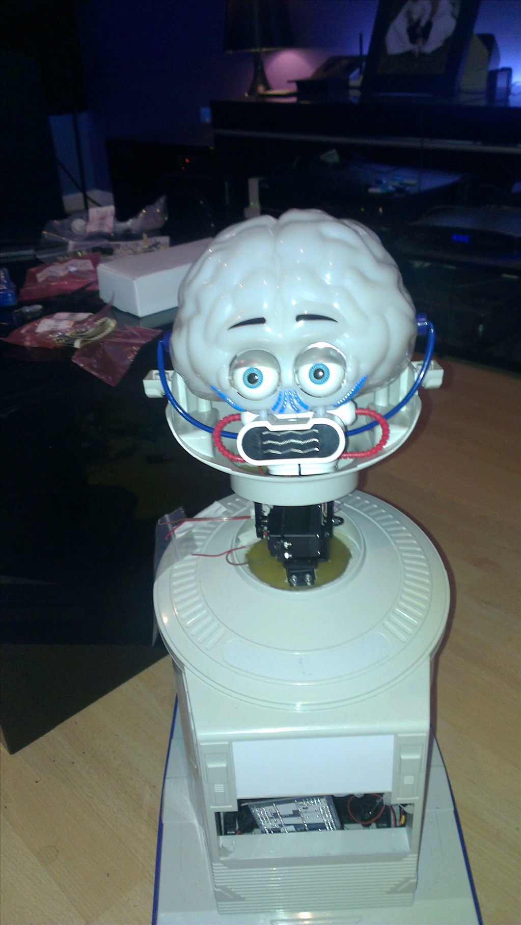
ust a few images of his head now it's got the new "nose" camera and been relamped... Tempted to leave the bubble mask off now (thoughts?)
The mouth light may change. If nothing else it will be activated when the robot speaks but tempted to change it to a chasing strip of red leds (like KITT's scanner)
Eyes are bright white, reason being my house is dark at the best of times so he needs to light up where he is looking with the camera, this seems to do it very well.
I kinda like that look without the bubble.
Finally got the batteries decided upon for this project now, 2 x 6V 12Ah sealed lead acids should do the trick and hopefully fit nicely in the base.
Also have the head all fixed up (short of bubble mask, which I'm almost certain wont be fitted) and the bottom of it fibre glassed and filled to make a good base for the pan/tilt bracket I'm waiting on.
The base of the neck is also all fibre glassed up waiting for the bracket, it's going to be a challenge fitting a strong enough pan/tilt bracket & servos in as I don't want it to have a huge neck but hopefully the bracket can be shortened if needed (or more likely half of it shoved up inside the head).
Was working on the arms last night but didn't have the guts to start cutting out for the servos yet. In teh process of making some mock ups for the arm joints out of thick card, EVA foam, PVA & fibre glass, so far they look like I could use them as the finished part but we will see once it's dried and fitted etc. I assume the standard servos in the EZ-Kit are strong enough to lift an Omnibot arm?
Also put the hands back together... I didn't note how they come apart so that was one hell of a puzzle, thank god for the old robots site and the Omnibot Companion guide!..
Still waiting on a bunch of parts and still trying to find a cheap enough Omnibot that I can use the battery panel cover from as the Hearoid has the Omni 2000 version with the extension ports which I've removed.
Getting there slowly, slower than I had hoped to be honest but it'll get there.
Quick (and short) updated before I go to bed...
Hearoid's neck is now fitted, although it looks too long to me so have a shorter C bracket on order which should arrive tomorrow or Friday. If that doesn't help much then I guess I will have to fix the bracket up into the head rather than fix to the bottom.
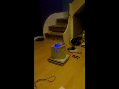
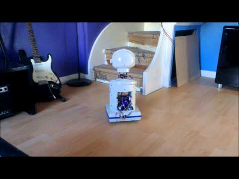
It's very top heavy at the moment without the base fitted or any weight at the bottom, which is why there are no videos of it moving just yet (I tried but he just wanted to tumble over causing me to throw the camera to the floor to save the robot.
Eventually, once it's the right length it'll be covered with some flexible duct.
I'll do more images, videos etc. when I get more time.
I have to say I've got so used to no bubble on the head that it just looks right now and with the bubble it looks wrong, which is great news
if you dont need the bubble ,i do refinish them to look almost new
You can make them nice and clear? Can you do that do a robie jr dome?
@rich I keep my solder iron tip clean with 400 grit sand paper. Works great cleans oxidation and carbon right off.
yes,bought a plastic refinish kit and 4000 grit sandpaper and 1000
It may not be much to you guys but it's a great motivation booster getting the HBridge wired up and working.
I'm still struggling with the head, well, not struggling I know what I need I just cant source it in the UK... Basically, the pan/tilt bracket is too long and it means the neck is as long as the head is high, which looks wrong even when the flexi duct is attached... That's tomorrow's project... then on to playing with tracking
can easy cut the bracket and make it shorter,one cut and splice it together or cut it to length and drill holes for the mounting of tilt servo ,can easy cut the end off and use that as a template to drill the holes
That's the plan. I guess I should have just fabricated my own bracket from the start, it would have been quicker and cheaper... At least I know for next time.
Well I've sorted out the neck although I'm not 100% pleased with it but it'll do for now... It's still longer than I had hoped and after having to cut down the C Bracket and in the end making it an L bracket due to friction etc. it's very springy... It's not that bad but will be looking for ways to support it better soon... I may even scrap the pan/tilt bracket and try it another way with the tilt fixed to the bot and the pan to the tilt mech to save space (I literally have about an inch of space to use before the neck looks too long.
The ultrasonic testing didn't quite go to plan. It seems there are issues with black furniture when it comes to ultrasonic and typically, most of my furniture is black. So an IR sensor is also being used (although has it's own issues one being unable to control the Movement Panel but that's a minor setback).
Now, as far as the electronics are concerned it's just a case of building the switching circuits for the eye and mouth lights and building the battery monitoring circuit... once I figure out which batteries to use (thinking some 7.2v LiPo batteries at the moment but that's changed a few times already).
I still need to build the arms and attach them. Stupidly I managed to trim off too much of the original mount so the servo horn doesn't reach the servo when fixed to the arm (as DJs method in his Omnibot), that's something I need to fix but it's nothing that can't be built back up or fixed with spacers etc.
I also need to work out how, if at all, to move the elbow joints without having any servos or linkage on show... or at the very least, servos made to look like they are supposed to be there not just bolted on the side.
It's mainly been playing around with ARC and EZ-Scripts lately, writing scripts for various things like testing the head movement up, down, left & right. Moving at various speeds with PWM. Building dance routines (I was bored, sue me)... just generally getting used to what commands do what, working out how far a Forward(255,1000) command will move the bot, how many ms it takes to turn 90, 180, 270 and 360 degrees, how to make the head nod or shake... Just the basics...
The good news is, in 2.5 days I will finish work for a nice long 2 week break to be spend mainly on the bot, so come mid January I hope to have him (or her, undecided on sex yet, it depends how awkward it becomes and how much it costs) ready to be painted up all nice and pretty.
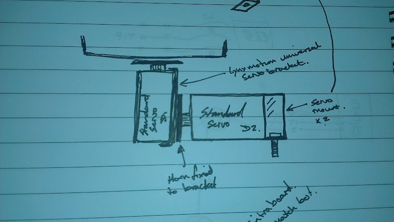
I'll also be posting more photos, sketches, calculations etc. soon... we don't see enough calculations and sketches on here IMO
Here's his head moving a little... controlled by the camera but really it was just picking up phantom faces (I assume due to low light levels in my house).
Like I said, the neck looks too long to me... It should be half that length.
I had a post about using sonars and IR,I guess you missed it Best way to use them and material that they cant detect,And on sonars it wont detect black material and more. Also ways to reduce the cone slope detection on sonars to pick up small objects in path,as thin as a pencil,one main item is table legs
I also work with metals ,plastics and some gears alot at work,i design at home my own servo gear boxes some better then you can buy (high torgue and low current)
RICH here is a idea i am using on my arms i hate plastics,not very strong,so on the inside of the plastic i cover it with a thin sheet of aluminium and then mount my servo's to it,makes the plastic much stonger and makes it easy for servo repairs nobody really thinks about it,just glue the servo hope it holds I do the same for my whole body of my omnibot 2000 project. Dont need to mount anything to my plastic body,no sensors or anything else check out my project my omnibot 2000 project
I agree rich , i love drawing the ideas for robots body and stuff. Yup his neck does have a giraffe thing going on. On my neck I just used an lynx motion bracket. 10 bucks. Not too long. I lost your email with your address rich email me agian so I can quote you on the clear dome/mask [email protected]
I not great in drawings and not good at it,put schematics i am super good at it.only it takes a lot of time I also forgot i have 2 HEAROIDS like your too ,havent made plans on them yet,one most likely restore for my big robot collection BUT the other one will have EZB in it,cant wait for APRIL a very big month no more work ever only build robots
On drawings may need JOSH on that,hope one day to visit him,but so much work,and then travel for work plus my big vacation with my girlfriend for 3 weeks in jamaica I never talk to much about jamaica ,but been there 53 times so far and best place ever to visit ALSO MY SEXY GIRLFRIEND IS JAMAICAN
RICH i see you are in UK,I went there 4 times so far great place many castles to see and people very nice,not like france or some parts of Europe what part of UK are you in
It uses the LynxMotion bracket, it had the long C on it which I changed for the short C and still too long, cut down a cheaper bracket for this but again, giraffe neck. The next plan is to reverse the servos so tilt is fixed to the body and pan fixed to the tilt servo (that makes sense if I had the drawing on me to upload)... If that still looks too long it's going to need the neck cut out and bracket fitted inside the body or head more... It's all about trying different things to find what works and looks right.
@robotmaker, I'm just playing with a bunch of sensors at the moment finding the right ones. I have no thin legs on my furniture so that's not a problem. It's all big and flat.
I'm on the outskirts of the Cotswolds so a few castles around here and a lot of nice scenery. Not too far from Stratford-Upon-Avon (Shakespears birthplace).
@jstarne1, I'm going without the bubble now so his face is exposed.
But, if anyone wants/needs it my email is rich[at]richpyke[dot]net
yes been there nice place,LEEDS castle my favorate, i have lots of chairs in my place with thin legs (bar stools) but the sonar reduce sid slopes not just for thin legs,i guess i didnt add more info on it if sonar has smaller detect zone (side slopes or cone) has a much higher accuracy navigation most problems is the corner of walls ,very hard to detect it,and door ways too pretty easy to make,also you dont use on every sonar only left and right sonars at a angle if using a radar not great 100% percent because first no pinpoint type of sonar ,like reducing side slopes ,second not a great idea to use it on radar because doesnt have a wide angle slope needed so you need both,just some ideas to improve navigation most really good robot builders will tell you for very good navigation you need all types of sensor.IR.sonar,LIDAR ,camera,and thermal and compass ,plus real good codes and a map every made sensor has its good points and bad points i love my maxsonars worlds best sonar for accuracy and super low current ,plus ultrasonic sensor it use is both to send and receive,so takes up less room current is about 3 ma on srf-04 types 35ma,cost it a little high,but i got very lucky instead of the $29.95 i got it for $12 new from a company that going out of business,sorry bought every one they had 30 of them dont thing the ones from china ,same as EZ sells i may not need them will sell them i know my grammar is bad,just no time to fix it
I already have a floormap of my house drawn in AutoCAD which is accurate to a few mm, eventually it may become a complete 3d model furniture and all but I've not had the time to add to it since first drawing it due to my workload. By using that along with calculating the distance travelled in a certain time at specific PWM values for the HBridge that'll be better than any collision detection using sensors (although it will need collision detection to avoid other robots (most likely my "whiskers" robot vacuum which isn't intelligent in the slightest), humans and anything I move or leave lying around... But that's all for future consideration.
This project is to get to grips with the board, with the sensors, with the programming, ARC, EZ-Script and the SDK. It's not a challenging build in the slightest, it's basically one of the run of the mill Omnibot conversions.
In other words, perfect collision detection and object avoidance is not high priority for this build. Future builds may be a different story, my ultimate project I am working up to (life size biped android) will be a different story but that is way in the future and needs a lot of time planning even before the build, calculations to figure out how to balance, how to move lifelike... I could go on but the list of challenges to overcome is already 3 pages and it's only a brainstorming activity at the moment... But I digress, more will come on that bot in a few months/years time.
thats been tried before doesnt work well at all,but does help ,a 3 d floor map it the best for navigation sometimes furniture moves alot in a house also.but using only pwm values is not enough,need compass and sensors to detect any changes in the house
that a design i am working on life size biped android with very real face emotions one reason i bought a very good lathe and milling machine cost was high but worth it on the robots here is this forum is too easy more for beginners a real good robot design i found out takes a lot of planning,like my omnibot 2000 project may take another 6 months or more,for calculations like torque ,making is very strong,balance ,big idea i care about super low wattage,too many dont care about saving current on a robot,i guess they dont care if it last a hour or 2 mine i get it to last 12 hours without going to homebase to charge and lot more on other stuff added to it
robotmaker, If EZB never has what is needed for all your hord of robots then why do keep comming back here? Seems you would stay with the platforms that seem to give you everything you require. Why do you insist on coming here and chat up other platforms over EZB and point out your conceived downfalls over and over again? mad
I GUESS you missed the point the other software lacks hardware and sensors and other stuff that EZB has ,that why its my favorate of platforms most all of my robot designs WILL USE EZB like the AI SOFTWARE,the board they use only have motor and feedback control,7 sonars only and 6 IR plus digital port,doesnt have any near what EZB HAS and any other board and a little slower processor,i think is 32 bit at 35 mhz and at the time (3 years ago) i bought 6 boards at $250 each hope someday to use both EZB AND THE OTHER BOARD together ,so not to waste good money ROBOREALM is working on a interface for EZB ,IT add KINECT,navigation and so many many video filters i know DJ is trying to get better AI,he is getting very close, and so far not many video filter for camera yet so your point is wrong (you would stay with the platforms that seem to give you everything you require) IT DOESNT not right to be mad at someone with that red avatar you put up ,its not very nice
will say it again one last time i love EZB a lot more then you or i would not buy 15 of them i thing is one of the best designs made,but like in lif everything as good and bad points including electronics been building robots for over 20 years and so far i see EZB might be the best
all roborealm is mostly for video filters about a 100 or more ,but many other interfaces roborealm list of interfaces and more get added each month,it will a very good add-on for EZB I heard also someone in this forum said that the EZB is almost max out i never get mad at all ever
Not mad, just tired of the constant negative and limiting comments. One or two are OK but you never quite. I get the point. Maybe I should have used tired
none of my points are negative or limiting at all,just the things i found using both board each has it own faults,but i think you think there is any bad faults at all faults dont make a bad board I LOVE MY EZB way more then you do and in the 9 robot clkubs i pass rthat info about EZB HOW GOOD IT IS, but only a few guys from those clubs like it,thomas and mel are 2 i told it about i dont know why they dont like it ,they saw the site and what it can do one club is one of the biggest robotics club and has club meeting at a college,may i go to the meeting its in calif i dont care for that state,since i travel almost all over the world there is a big robotics convention in china this time,hope my work will let me see it just one day going in march there for work
Anyway...
Finally got around to focussing the camera and getting camera tracking working... Not very well for some things due to the lighting conditions of my house (LED warm white lamps aren't the greatest for light output but haven't finished the living room yet).
Tested in the kitchen where there is much better light and it's pretty good at face tracking, colour tracking and movement tracking. Especially now I've setup the config correctly!..
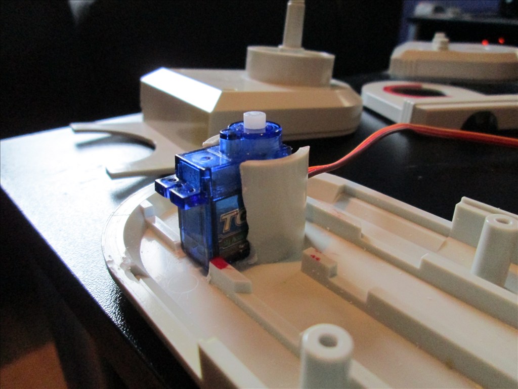
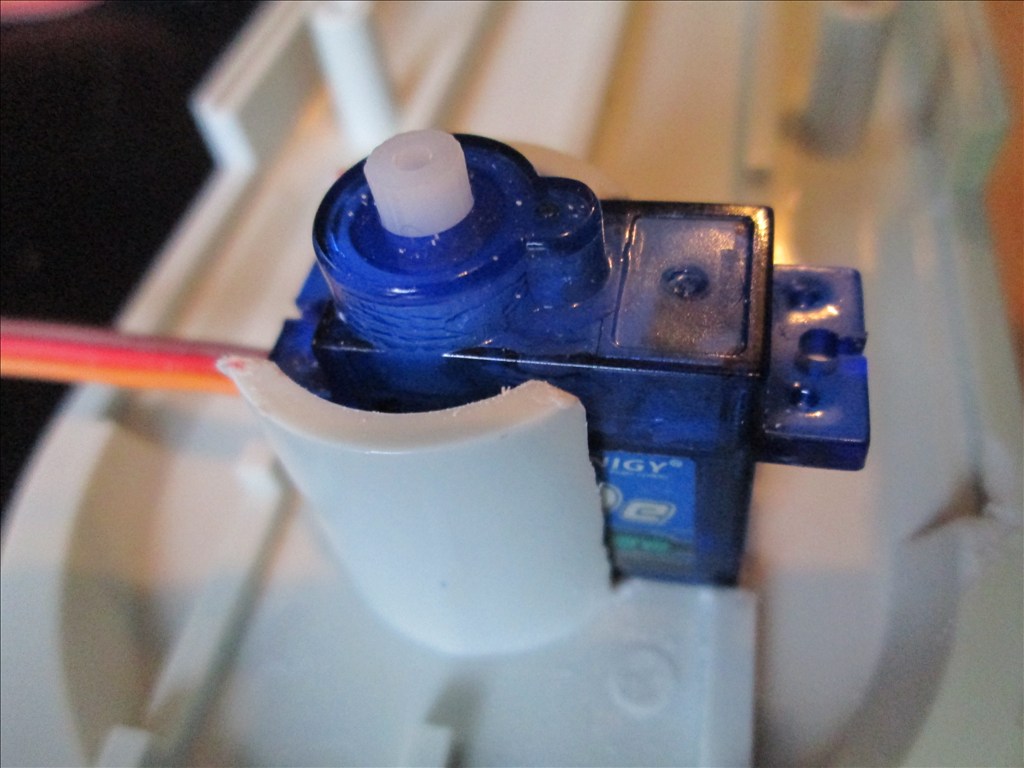
Front panel for the sensors is now all designed too, ready to be made out of some nice Sintra, cut to fit the upper opening in the body's front (where the digital display is on the Omnibot). I wont be rotating the sensors on a servo for the radar, it will be fixed to face forward only.
Have also decided to go for LiPo 7.2v batteries, to start with a single 5000ah and will see how long it lasts before needing to be recharged. Not ordered anything yet though, no point this close to Christmas, it wont be dispatched until after Christmas anyway, so plenty of time for me to convince myself otherwise (again!.. Gone from SLA to LiPo to NiCd to god knows what else so many times so far)...
I am having a few issues with the bluetooth disconnecting though, it may be brownouts or it may be the bluetooth dongle's range, it's something I need to look at. If it's due to the load of the servos and hbridge I'll just knock up a small board which supplies the servos their Vcc without going through the board. The HBridge power is direct from the battery so I know it's not the DC motors causing it. Could be the battery I guess, it's the replacement 6v 4.5ah SLA I got for the Omnibot which I have read is good for power so chances are low.
And I've finally triggered my electronics knowledge that's been stored in my memory for 15 years but not used in as long, I can't believe I struggled to figure out how to build a voltage divider but that's the human brain for you. The good news is, now I have a new soldering iron which actually gets hot enough to melt the solder, I haven't lost my soldering skills... Perfect solder joints all shiney and rounded (unlike the dull flat dry joints my gas iron was giving).
Finally, I'm tempted to keep the neck as long as it is. I'm not 100% sure if the last youtube video I put up was with the long C, short C or modified C bracket (I can't tell...) but once the arms are attached and it's all painted up in it's new colours it should make the neck look a bit shorter... but we will see... that's an easy change to make if it doesn't look right after then.
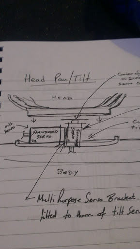
P.S. Couple of sketches to explain the neck pan/tilt option I tried explaining earlier (apologies for poor quality, taken with camera as scanner is upstairs and I'm lazy).
on the bluetooth problem i have the same problem DJ SAID it was RFI and i agree with 100 % my setup i have almost all my computers 9 of them on WIFI with 2 on 1GIG SETUP Second is i have a X10 MODULES on everything in my house,inc pool and spa,a/c (i love my X10) 100 % FULL AUTOMATION control of everything including my kitchen stuff second i have one of the strongest WIFI SETUP with special antenna so i dont know what is causing it,one reason using direct connection or WIFI to EZB on my pan and tilt using a custom design 360 pan and full tilt foward ,back and side to side .plus at the same height as orginal has
I kinda agree with dshulpius about robotmaker. We always seem to hear both extremes within the same posting,robotmaker, and while its good to hear of shortfalls(few) of EZ-Board/Builder its does get tiresome . I think your pretty amazing robotmaker with all your experiance but try and make your comments positive and not keep bring up the same negative ones! Thanks for your positive postings and understanding IMO
And, for the love of all things robotic, keep it to your own posts!..
My Hearoid WILL be using the EZB, will be programmed by me using ARC and EZ-Script, with all due respect, I don't care about anything else, at least not in this forum topic. This project is intended for me to learn about the EZ-B and the basics, nothing more. No fancy AI, no linking to billions of other bots.
So, please, use the topics you have already started regarding other boards, software etc.
i disagee with you on some of it,only problem i might keep saying it alot but it nothing really bad about it and other reason person who started the post didnt hear of the faults ,so it mostly for his post only
same if i bring it up again it will be for that persons post too,to give ideas nobody should say my faults are wrong unless that tried that software,so how you you know is good or bad its also good to bring up negative ones or they never will get fixed Thats the main reason i bring it up also not every board made is perfect
ok i look at my posts in this tread it ,i really didnt say much about the EZB BOARD on how bad it is,i might of missed it
some of the points or idea's giving to RICH was first about sonars ,since i know more about them then most people do and other sensors samne about navigation since i tried a few and see some professional designs that only uses sensors,lidar or sonar or compass and so many more and there the best designers in robotis,witch in calfornia i had a good offer there working in the robotics lab
same with the pan and tilt and the arm problem he had,gave idea i use alot because plastic is cheap and breaks alot,plus easy to remove servo's and there are other points too also i did mention about going on my trips (i guess thats not good for any posts) but i see other does it too so thought it was ok i did bring up i buy professional robots ,no matter the costs only to look at it and take it apart and try reverse engineering to use the ideas on my robots
RICH i thought you wanted to here other persons idea ,only trying to help you
I welcome and am thankful for any suggestions and any constructive criticism on my project and how to achieve my goals using EZB and ARC/EZ-Script.
But, your posts about how your AI software is great and ARC isn't are spilling all over every topic, as are many of your other complaints.
doesnt seem from your other post that you like any of mine
update i remove everything not related to this project ,if i missed something let me know like i said only trying to help you since i MAY no more about robots then you,i dont know you or how long you working on robots or working with sensors or software and yes i will keep all my stuff to my projects only ,i sometimes get carried away mostly about my work, Only trying to give you ideas on AI software or sensors or brackets or anything else for you project dont have to use them only a a idea thats all you say you really dont care i think about other ideas since you are doing the program adding sensor by your self,people here might have ideas on script to help you are anything else also never check the software too,so nobody can say its bad or good except me worst thing about it is NO NO EZB HOOK UP.but EZB I AM GLAD is almost there,i hope soon it is
Useless post removed
i would do the same on my projects also if anyone has a good suggestions on how to achieve my goals too
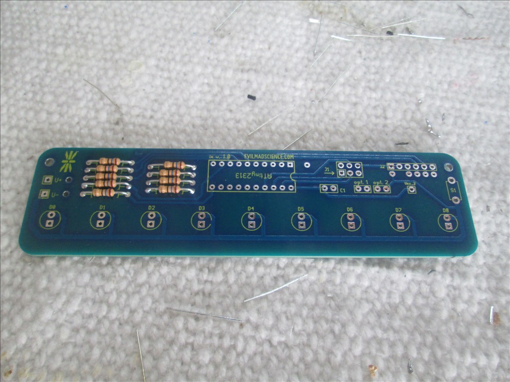
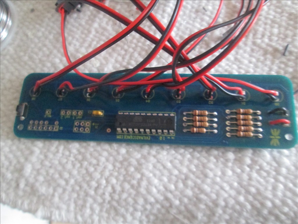
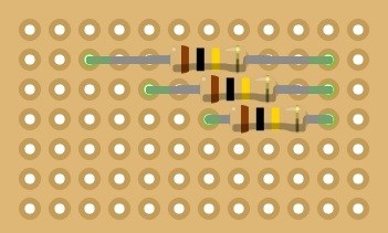
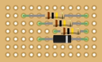
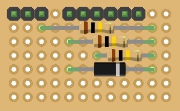
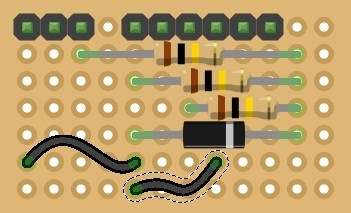
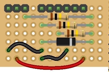
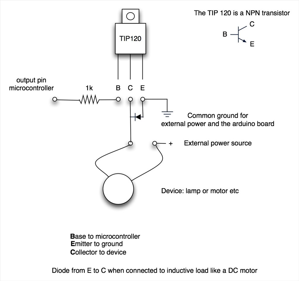
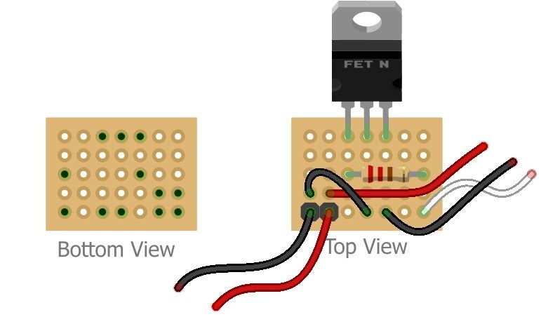
My TIP122s turned up the other day along with the 1k resistors needed to make the switching circuits for the eyes and mouth lights so immediately these were quickly soldered together and fitted to the bot. It's the usual TIP120 circuit so I wont post any pictures or schematics (unless asked for them).
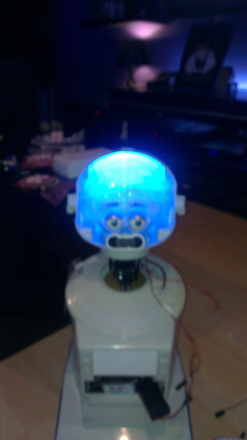
Then quickly adjusted the "head test" script I wrote while playing with EZ-Scripts so it would flash the eyes and mouth 5 times quickly before and after the movement test...
I also finally got around to taking a look at how to mount the servo to move the elbows on the robot today. My biggest challenge is trying to make it all look like I haven't touched it so where possible hiding the servos inside the robot and inside the arms. The other challenge seems to be getting everything in without using hot glue or epoxy as it all needs to come apart again for when he receives his new colours (thinking a slight metallic white for the main body with a nice metallic candy blue for the face, hands and anything else that was originally blue on him, but that might change)
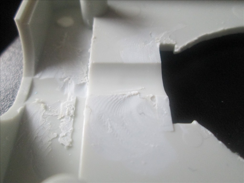
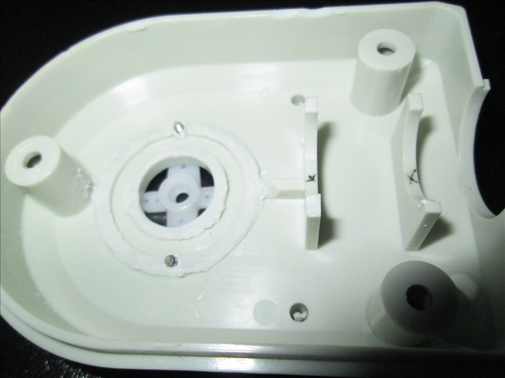
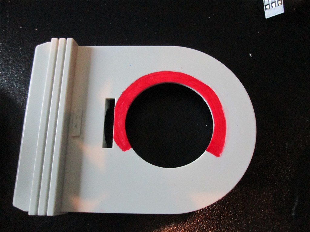
To do this would mean grinding down the original mounts;
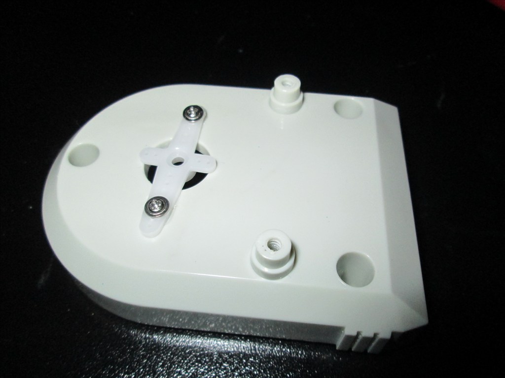
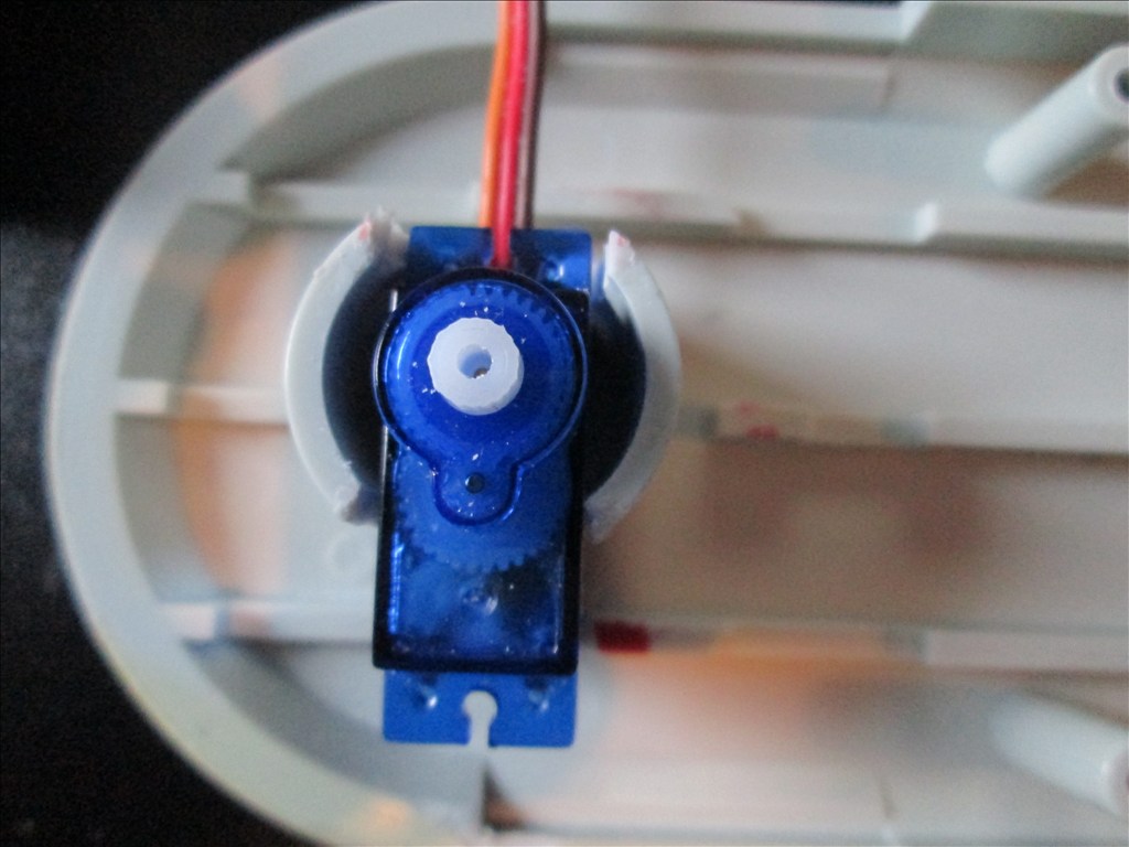
Offering up a mini servo seemed to fit perfectly;
Trimming away at the first half of the lower arm so it can rotate, all the red needed to go but avoiding the original mount for the screw;
This does mean the elbow can't rotate a full 180 degrees but can yours?
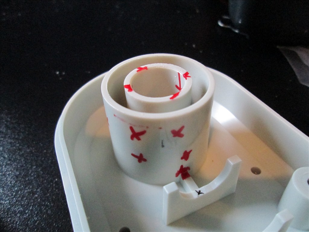
And the other half also needed the original mounts grinding down (everything with a red x on) for it to all fit back together;
It's all ground down now and ready to be fitted back together (tomorrow's job, it's 2:30am here!) The photos of the parts ground down ready to go are still on the camera so I will post those up tomorrow.
It should all fit back together nicely. A servo horn is screwed to the piece where the join for the upper and lower arm is which should be hidden nicely when all on the robot. Hopefully the mini servos will have enough guts to lift the lower arms - they seemed pretty strong when used on the pan/tilt bracket (but not strong enough to lift the heavy head).
And because I've been grinding and cutting the arm parts and I've not exactly too confident with that just yet I kinda wimped out a little and won another Omnibot on ebay today just in case... the good thing is, the new one is complete in original box too, so depending on it's condition he will either be kept nice and original in his box or swapped out for the one I bought a few months back and the other used for parts if I need any (if I don't then I have my next EZB project)
It feels so much better now it's finally coming along, things are moving and starting to take shape.
Looking really good. I love the movement of the head.
Your doing a great job! Don't worry about the range of motion. Most people only have about 100 degree of motion. My. Shoulders and elbows are 220 to 240 degrees range of motion because I surface mounted the standard servos and connected them with push rods. Its more than anyone needs anyways lol. Can you post exactly how you did your circuit for your lights to turn on and off? Could be a great wiki submission. Thanks bud! - Josh S
I'm undecided on the length of the neck at the moment. It was longer than that too but changed the pan/tilt bracket from using a lynxmotion long c to a short c slightly modified. I may, when I get chance, try just fixing the two servos together using the universal bracket and cutting a slot for the pan servo with the tilt servo fitted to the base...
Apologies for the poor sketch and even worse photo of a sketch.
But then that would restrict the already restricted range (currently 50-70). I guess I will see how bored I get over my 2 week Christmas break.
@Josh, I'll do a video when I do the third one (want the eyes to be switched individually).
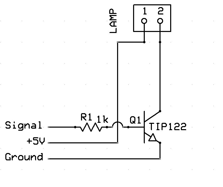
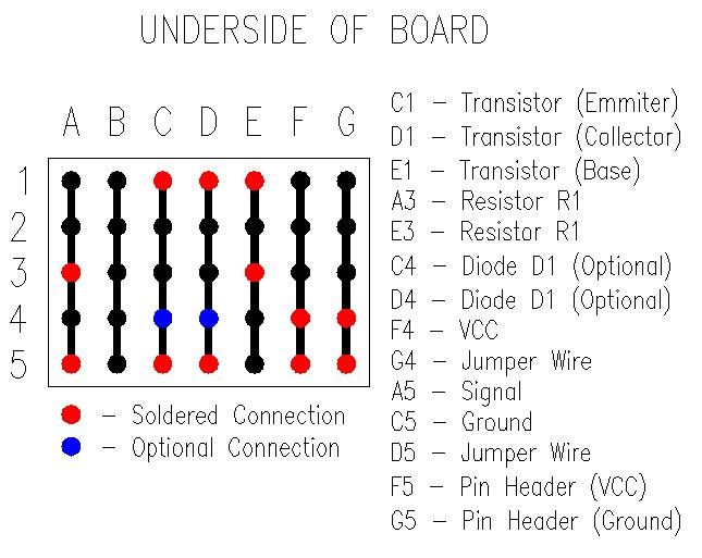
In the mean time, the schematic
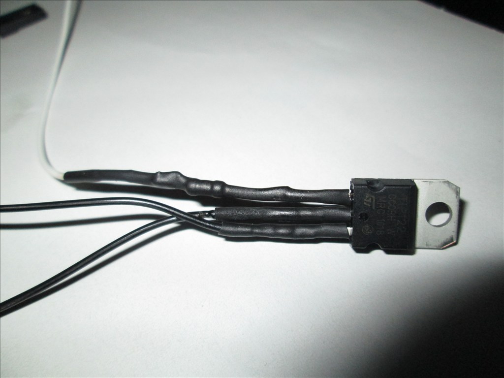
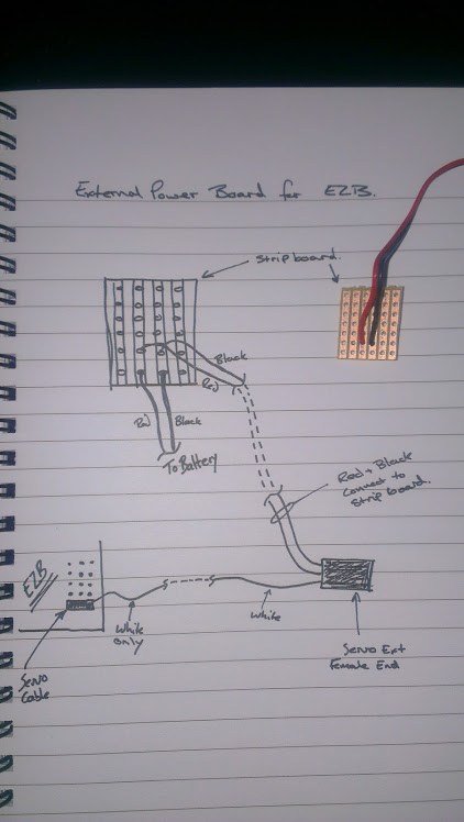
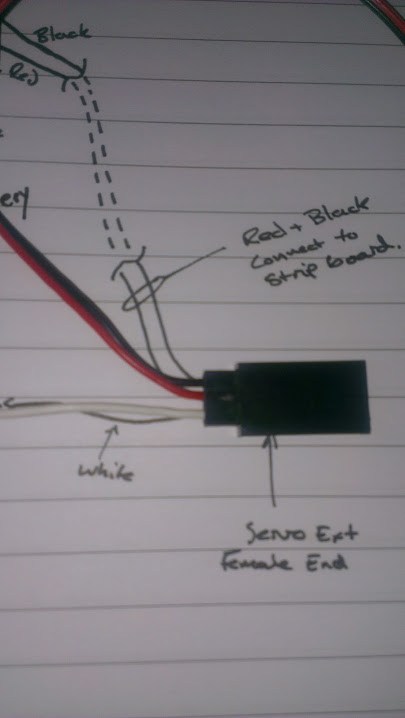
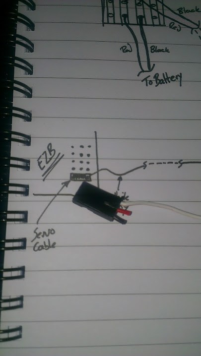
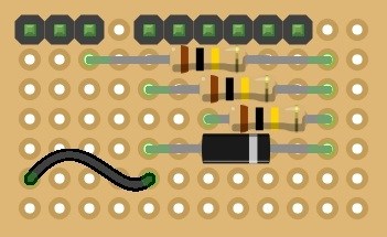
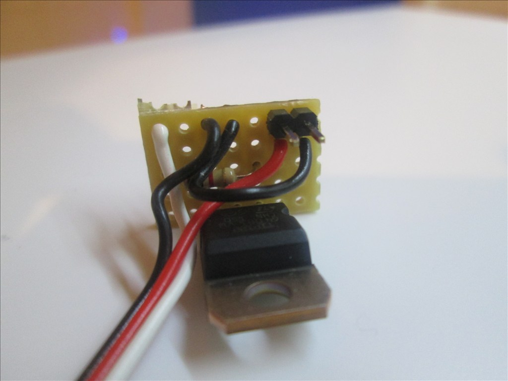
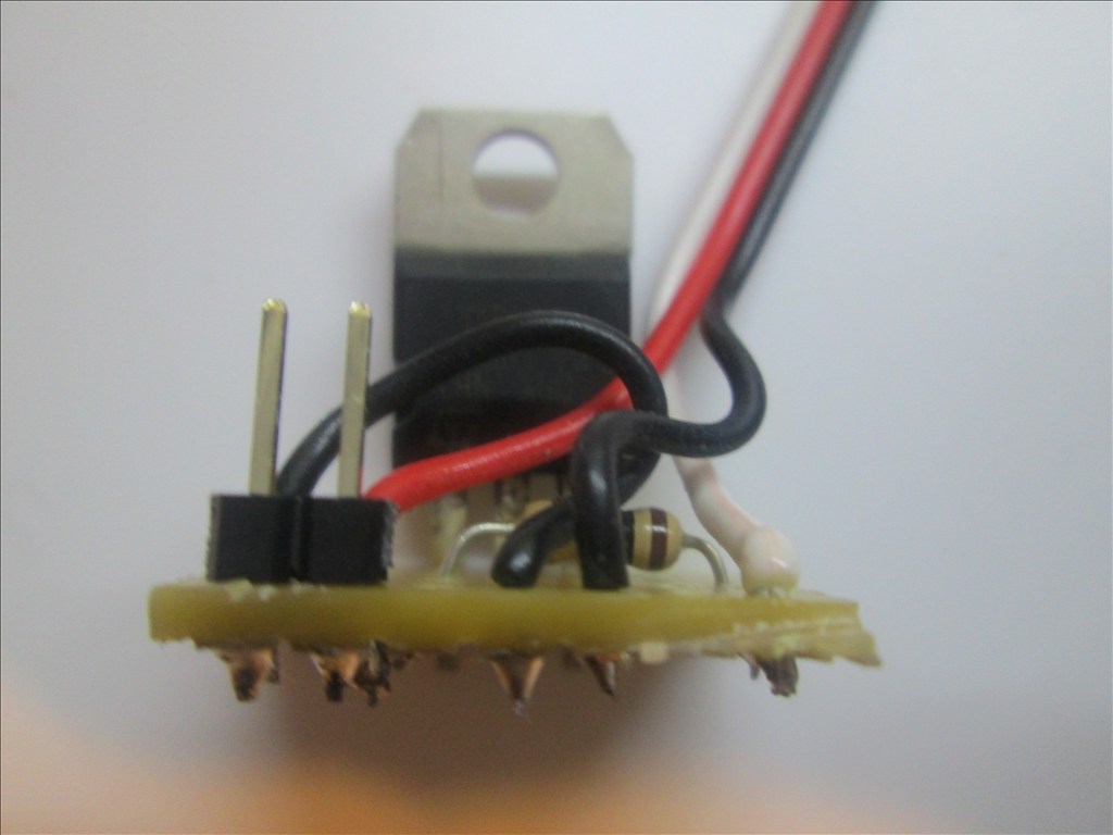
For ease I used a servo extension cable, pulled off the surround of the female end to expose the three pins. Cut the white wire, soldered it to the 1k resistor, the other leg of the resistor went to the base of the TIP122 Cut the black wire about half way, the half connected to the male connector (EZB side) was soldered to the emitter. The other half of the black wire went to the collector. The red wire was left alone. Using the existing plug on the omnibot wiring I plugged the female end of the extension in to the plug. All soldered joints were covered with heatshrink to protect against shorts.
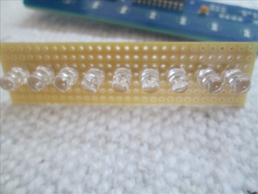
If using LED lamps the eye circuit needs rewiring due to Tomy's weird way of wiring it up. Also pay attention to the polarity, the red wire needs to go to the positive of the lamp.
You may want to re-write that if it doesn't make sense, it's 4:30am and I've not yet been to bed...
Nice job! Excelent crafstsmenship. You must be giving your drummel a work out. I like the way you used a cable extension and used the end as a socket to slip over the resistor. Useing the remaining wires to complete the circuit was very neat.
Thanks for the schematic. Hope you get some sleep now.
Well I still haven't been to bed... had too much to do for Christmas so just stayed up all night (I'll pay for it tomorrow).
Just spent the past half hour playing with the arm again and unfortunately it seems the mini servos aren't man enough to lift the existing plastic hand (never realised how heavy they are). So I will need to revisit that after Christmas and see if I can find a way to make it work (claws are an option but wanted to try and keep it as original looking as possible).
I may try the possibility of fitting springs in the arms so that there is always a force puling the arm up to aid the servo on the up movement and hoping gravity plus the servo will be enough to pull the arm down. It's all ideas at the moment (so any others would be very much appreciated)
Yes my "dremmel" (cheap mini grinder set which was a quarter of the price of a dremme) is getting a lot of use and my kitchen is getting covered in a lot of small bits of plastic. My own fault for not wanting to go outside in the cold and wet to do it and as I live alone I have nobody to complain at me about it.
A few more photos as I had the chance to pull them off the camera;
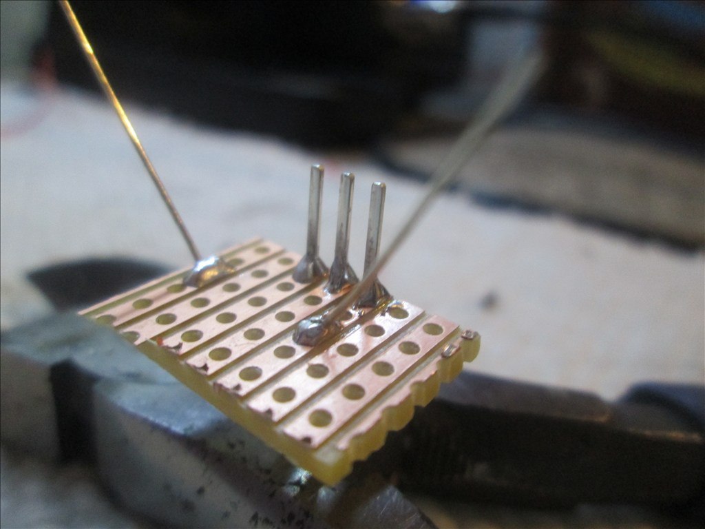
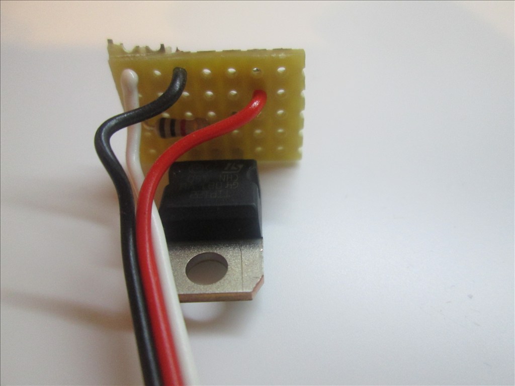
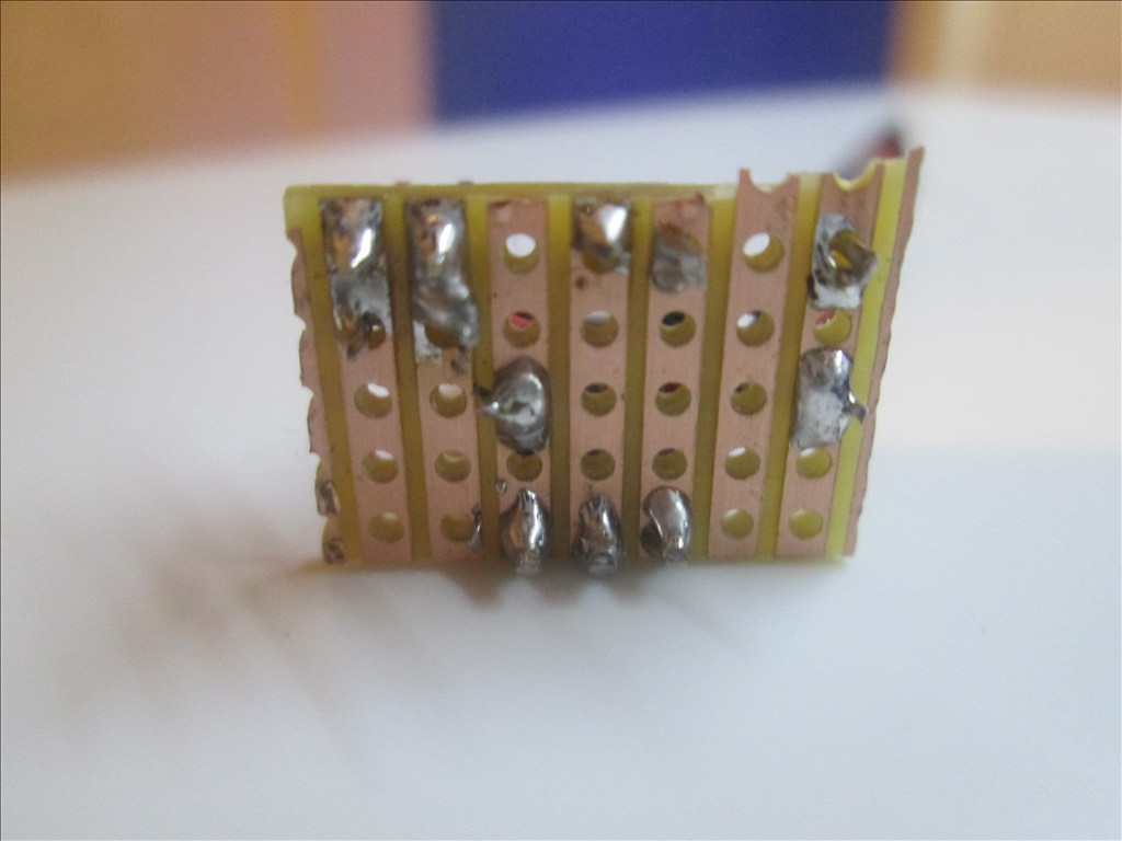
And some photos of one of the TIP circuits. Note, the resistor is covered by the heatshrink but it is on the white wire fixed to the base of the TIP122.
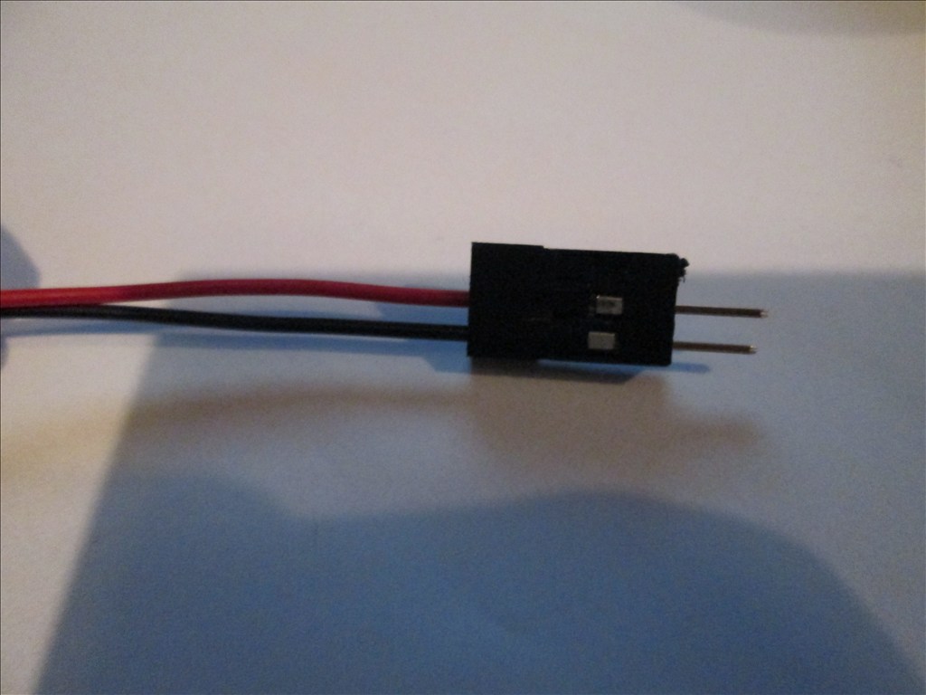
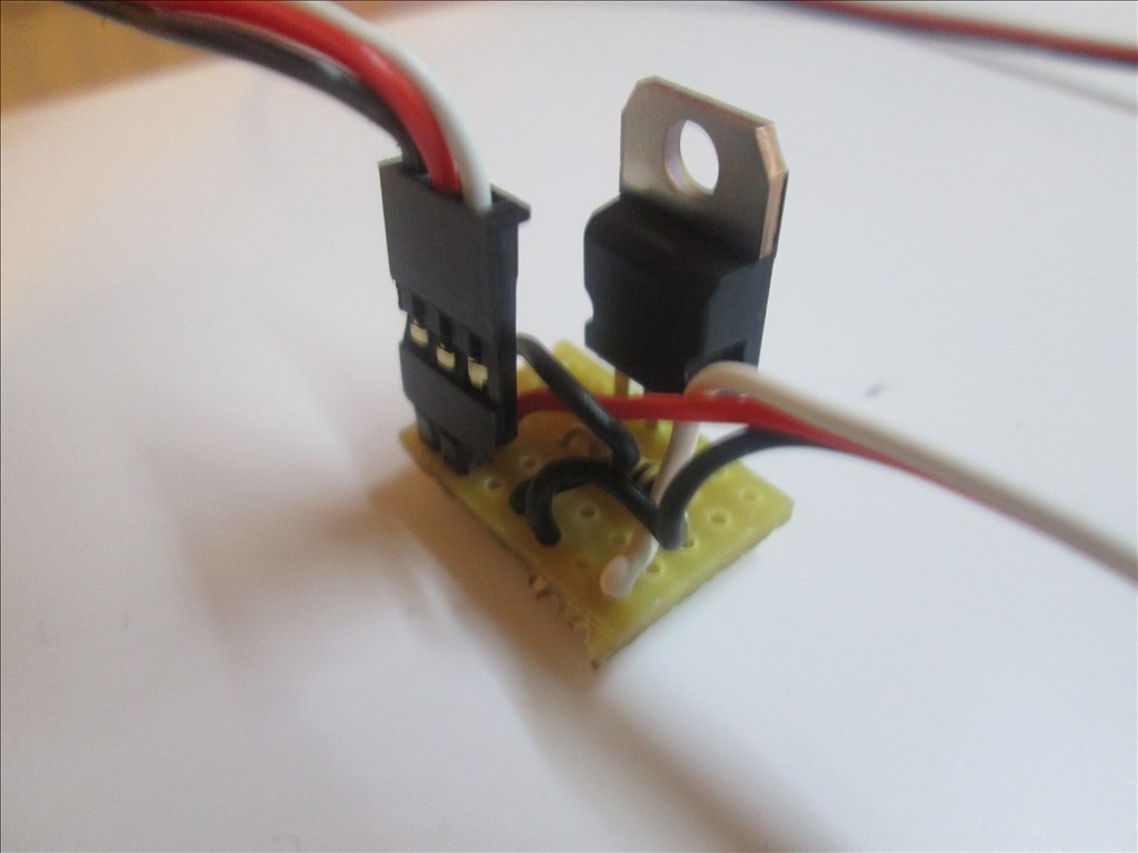
And the end of the extension cable which plugs directly in to the existing wiring of the Omnibot/Hearoid head for the eyes/mouth;
Unfortunately it doesn't lock in to anything so a slight tug and it would come apart. That is something I need to look in to, be it a dab of glue, a piece of tape or soldering that end to the internal wiring.
A small update on the arms for the bot. Typically I didn't do any calculations for the servo torque needed to move the elbow/lower arm and the micro servo fitted wasn't man enough for the job so it needed upgrading.
I found the highest torque micro servos I could get which were around the same size, although slightly taller which causes a slight issue but nothing that can't be solved.
I also found I cut the existing mount on the arm where it fits to the torso too short so please excuse the crude card covered fibreglass extension (which is surprisingly strong!).
Anyway, photos...
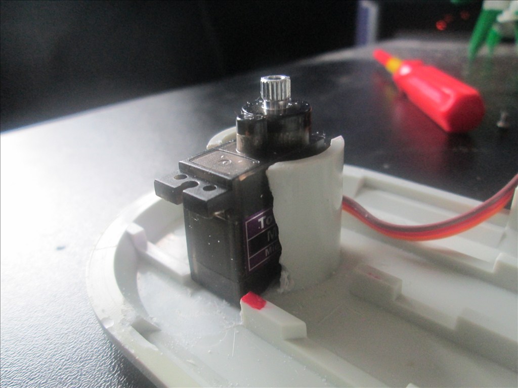
Tower Pro MG90S fitted which will (hopefully) have enough torque to move the arm.
Currently just superglued in position as it'll come out when it get's painted. I'll probably permanently fix it with glue, fibreglass or possibly just milliput it in, dependant on space available.
Cleaned up the inside of this piece to allow for a smoother movement.
Because the original shaft from the hand clashed with the movement I decided to cut it off and fix it with one of the micro servos originally intended for the elbow. This may not work with the claw hand as the original mechanism goes in to the shaft but I'll cross that bridge when I get to it.
Again, the servo is just super glued in position but will be fitted better once painted.
The elbow is mounted to the servo like so. The horn broke but it's not an issue as I need to space the horn away from the plastic by about a mm or two anyway, and then it'll be covered in plastic to form a nice hump that looks like it has always been there.
Inside the hand the servo horn is fitted with hot glue. I know I have said I want to avoid it where possible but I had little choice when trying to get the horn in the exact position. I may trim the hot glue down a bit at some stage and even may replace it all.
The servo cable for the hand rotation pops out here. Enough of a gap is there to avoid any rubbing from the elbow servo.
Then a nice slot cut in the shoulder for the hand and elbow servo cables to come through, again with enough space to avoid any rubbing from movement.
The elbow doesn't quite have 180 degree sweep but I didn't want 180 degrees anyway, it's pretty much exactly as I wanted.
I'm yet to test it on the bot but have tested it off the bot and it can just about lift the hand from the elbow servo. The shoulder servo in the torso may need upgrading though as the arm is pretty heavy now, that's the next job but need some milliput and plastic card to build up the inside of the torso a little to support the servo and make it hidden from outside the bot.
He is getting there now though, and the software side is looking good too with a bunch of scripts written, servos set up, digital ports planned etc.
Another hint on your light switching circuit,you should add a cap,so the light slowly comes on the light will last longer and no burn-outs
It's not my circuit, it's the one that's been floating around the forum for a while. I did think about adding a cap for smoothing out the voltage (didn't realise it would bring it on slow - by slow how slow?) and a diode (which is sometimes shown) but for the sake of this build, and because I don't have any, I decided against it.
The head is complete now too, I decided against two switches for the eyes as I am getting low on available digital ports. I only have 3 spare and that's without the MP3 board which I may put in there.
It takes about .6 volts to about .7 volts to turn on a transistor,when a cap going to ground as it charges it slowly ramps up the voltage,mostly a mosfet is a little better,but a transistor as voltage is apply to it ,acts like a resistor and slowly turns it on DIODE is not really needed ,only needed on relays for back emf spikes very rare that transistors are used any more for switching,mosfets are much better,lower RDS ON and more
Looking Really Good! I am anxious to see your arm tests.
Me too Bret! I just hope they work as I can't get a stronger micro servo than I fitted and really want to avoid having it on the outside of the arm. I calculated it roughly and it's pretty much on the limit of the servo, and I think that's when horizontal so lifting the hand above horizontal may be a struggle... We will see...
If everything goes as it should (i.e. if my milliput and plastic card turn up tomorrow) I should have one of the arms fitted some time tomorrow for a test.
The arm is fitted and connected up, and I just did the first arm test (see video - it's pretty much unedited so excuse any long gaps of nothing happening while I was changing settings in ARC)
It needs stronger servos for the upper arm joints but I think that's a pretty good result. The hand rotation is perfect and smooth. The elbow servo is borderline OK but it's as good as it's going to be.
The hardest part, fitting the arm! The servo horn for the upper arm is inaccessible with the arm put together but needs to be accessible for fitting to the robot. The arm needs to be together before it goes on the robot. What a nightmare it was feeding the cables through the tiny holes made just about big enough...
So anyway, need to order some heavy duty servos now, the one used was the standard servo from the EZ Kit, so I know I can get much stronger ones.
In the mean time I can firm up the arm, which will add more weight but not that much more so it should still be OK once done.
Are you running 6 volts to the metal gear MG90 servo? It can take 6 Volts and that will be the best torque you can get from it. All of mine are that same servo and run on 6 Volts. A separate power source than from the EZ-B - this will be the optimal for those little servos. Just tie the power to your 6 volt battery and only run the signal wire to the EZ-B
No, until about 2 hours ago I didn't realise I could give them their own supply, it's now on the to-do list for at least the elbow servos (if not all servos) to give them a bit more torque and reduce the chances of brownouts. Although I'm using a 7.4v lipo now so I guess a voltage regulator will be needed but that's no problem.
i would use a LDO (low dropout) regulator,i use them in every robot design,and we use them for all the test equipment we sell at work. there is DC-DC converters too,but they waste more power. 7.4 volt battery is near the border line of a circuit using 6 voltswnen near low battery voltage 7.4 VOLTS mostly good for 5 volt circuits, IT will work only you will have the battery drain fast from servo's
Battery drain isn't a major concern to be honest, if it drains too fast once it's done I'll change the battery for a bigger/better one, or throw more in there (plenty of space and they are very light compared to the old SLA which was in there).
I don't know if something is out there but what I picture using is some kind of servo bus, a supply in of 6-12v, regulated to 6v and then a strip of connectors with the Vcc and Ground... Like the EZB but without the processor etc. I haven't looked yet but that's, if they exist, what I'll be looking to use. Otherwise I guess I'll have to make my own (I may do that anyway)
I guess the SLA I used to test the arm with is going flat (I've never charged it since I bought it and played with the Omnibot I bought it for for a few hours so I am not surprised) as I just hooked the LiPo up to the EZB for another quick test and it moved much better, although will still be upgrading the servo on the top of the arm and running a separate 6v supply to the arm servos.
Now to figure out how to fix the servo horn to the top of the arm as hot glue wasn't man enough for the job. Also need to cut out the old battery compartment in the back as it's not being used now, make and fit some brackets in the robot for the hbridge board, ezb and something to keep the servo wires away from the wheels, cut out for the sensors on the front... So plenty to get on with while I wait for the heavier duty servos to turn up. I may even take another look at the neck and see if I can shorten it (although it's grown on me despite it not looking 100% correct)
sounds like good progress
A small update;
The battery compartment has now been removed (what a horrible job that was to remove whilst keeping the back door usable) and the front is filled with some Jervis plastic card ready to be cut out for the LCD display, volt meters (yes plural, one for each cell), IR and Ultra Sonic sensors.
The arms are still being worked on, a lot of milliput has been used in small doses to build a nice surround for the servo to keep it in there nicely without having to have screws and bolts holding it there from the outside. Although I am having issues connecting the arm to the servo still as the existing support with the horn milliputted to the end is long and the tiny screw seems stuck in there at a funny angle and wont budge (but it will do when I get the drill in there again!)
I've also taken the advice of using 6v direct to the servos for the arms, elbows and hands. I ordered a lipo regulator (Etronix LiPo Regulator 6.0V 5A) which is supposed to be used to connect a lipo to a 6v receiver but as long as 7.4v goes in and 6v comes out I don't care what it's supposed to do. but there is no indication of which way round it goes in the circuit (i.e. no label for supply and load) - anyone have any ideas? It has JST connections (male one end, female the other)? Or am I going to have to try it one way and see if it works and turn it round if it doesn't?
It's all getting there but has slowed down with me being back at work as of this week and having a lot of my own work to do when I get home too (both self employed and employed full time to fund the robot habit but it loses me a lot of time to play!)
Oh, and I almost forgot one of the best things I have done, which is to have ARC interact with my home automation via EventGhost... We have all seen DJs Omnibot watching TV I expect, mine can choose what he wants to watch or listen to (on XBMC)... I'll go in to more detail when I have more time as it's not a simple set up at all (uses a Windows PC, a Ubuntu PC, web server, PHP scripts, EventGhost, XBMC and probably more that I've forgotten about)... But basically, I could have my robot be doing his own thing, exploring or whatever and when he "walks" (or rolls) in to the living room he could stop what I'm watching, throw on his favourite song and start dancing Now that's something you can't do with just any old controller... I have an idea for a video now too but the robot needs finishing first...
My door on my omnibot comes of easy with the right tool I really like EVENTGHOST MY whole house uses automation,every outlet,every light,plus A/C control.pool and spa control ,alarm and more mostly use X10 modules,
Another item you may look into if you dont have already is USB-UIRT it uses EVENTGHOST to control everything IR (stereo's and tv's and more) and with a IR REPEATER system only need one IR SENDER and then emitters on each item to be controlled
ALSO one of my robot uses USB-UIRT module controlled by a AI software
THESE are ideas you may like or dont like
ON the LI-PO regulator, the way i think it works its a step-down to a step-up dc converter or step-up to regulated 6 volts output.
I opened up the regulator but couldn't follow the circuit board, it'll work for any source so I'll throw it on a 9v battery to test it, it'll save setting the lipo on fire or anything stupid like that. Basically in there is a coil, an IC, some resistors and a capacitor - nothing too complicated.
I looked in to IR through EventGhost but most of my stuff is RF controlled anyway (via EventGhost) or has an API for network control and what is IR controlled never gets touched anyway other than the TV power. It's tempting to throw in an IR repeater for those IR controlled devices (basically TVs and amplifier) but it's not worth the cost (both financial cost and the cost of building it all in to the fabric of the house and making it invisible - there's no way in hell I'm chasing out brick walls and replastering again!) but that's on the digital house (not home automation, it's specifically not completely automatic) side of things not the robot (I need to remember this robot is just a pet and nothing more).
here is info on USB-UIRT with EVENTGHOST
USB-UIRT THERE are wireless IR repeaters Thats funny a robot PET mine is my helper,my friend and more working on a design (almost done) to fetch a beer,but since not EZB related cant post it
I agree robotmaker"mine is my helper,my friend and more" since watching bicentennial man (1999) for the first time.
I'll have to watch that film then Always looking for new robot films to watch...
This is my first project of many and really a test of what I can and can't achieve with the EZB and ARC, and testing my construction skills - especially with the stealth servos, not a single servo, cable or extra screw (to original Hearoid screws) externally but servo powered hands, arms and neck (so far so good).
I have plans for helper bots in the future, one being a life size android version of Iron Man, War Machine or possibly C-3PO built totally from scratch using Papakura, card, eva foam, fibre glass etc. (cosplay costume maker methods) for the outer shell and an aluminium or carbon fibre inner frame - that will be quite some build I'm sure but a long way off.
Besides, I already have a helper bot named JARVIS who runs my house (yes, JARVIS from Iron Man was the inspiration for it, mine is a dumbed down, more domestic version) but it doesn't use EZB as he is not a physical robot but a more virtual one, running inside the wiring of the house, inside all PCs through a combination of bespoke software and specialist software - all of which can be interacted with via ARC and the SDK through the HTTPGet function, TCP and Telnet
Lol and im making the physical version of Jarvis
My main robot project is JOHNNY FIVE from short circuit movie got some parts so far,thinking total build is near $500 ,like the R2-D2 project like many others working on and made them already i bought while back the wooden prop from the first short circuit movie AND WEBSITE input-inc.com almost has the plans ready for full detail and full size johnny five
I am more of a robot NERD collecting every type of robots and movies
Just tested my LiPo charging circuit and it works great, if not slowly, but that's fine for this application... I guess charging at 0.2c (or 1/5c) isn't the fastest way to charge but it gives a very balanced charge with next to no heat given off (so little heat that I'm not at all worried about the fire hazard of charging a LiPo and will use it unattended without any fire containment precautions).
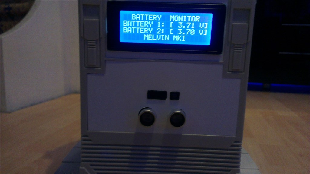
Basically what I've done is used the Turnigy 2S/3S charger which feeds, via a 2S balance plug extension, the 5000mAh battery. I cut the balance plug extension and soldered in a servo extension, 1 wire from each of the balance plug wires, this then feeds the cheapo LiPo voltage alarm/tester to save having to change over from charger to tester manually. Eventually this will change to feed two 3 digit 7 segment volt meters, one for each cell, which will be fitted in the instrument cluster on the robots front (where the tape deck once was).
All of this will be fitted inside the robot once it's ready and an extension wired from the 12v barrel jack of the charger up to the original Omnibot/Hearoid charging barrel jack so the 12V 1A power supply plugs in like the original charger would have (and eventually the robot will back on to this when it triggers the low power alert in ARC).
It's late now so it'll be tomorrow (if not later) than I get some photos of this put up.
The next challenge is to move the two LEDs from the charger to the front of the robot so they are in his instrument cluster. And also figure out a way for the EZB to know that the charger has completed (green LED turns off when done, thinking a simple transistor circuit, LED +ve to base, so when it turns off it stops current flow through collector/emitter andt he EZB detects a 0v on an ADC port)
I've taken the advice of 6v to the servos for the arms and it works great now.
It's a bit fast now and needs setting up correctly in ARC but there is enough torque in the elbow servos now.
The top of the arm servos are still going to be changed for some higher torque, metal gear ones too once they turn up but this means I can get on with the other arm and that'll pretty much be him done other than the LCD and volt meters in his chest, and paint of course.
I'm torn on whether to put 6v to the drive motors or go for the full 7v-8.4v of the LiPo, 6v sounds safer as they are fine at 6v, speed is good, noise isn't too bad and I know the motors can safely take 6v.
Thanks for sharing Rich,robotmaker, and Josh, your projects/visions are great! Since just receiving my EZ-Board I hope to reveal FRED as parts come together.....in the Project Showcase(thanks Josh)
You name your robot FRED,thats my name
I've just put him all back together, hidden everything inside and given it a good test and, well, I'm not happy with both how the arm looks and the constant servo buzz coming from one (or more) of the servos.
It may be another story once I firm up the mountings for the servos etc. I've not permanently fixed anything yet as it's all coming apart again when he gets painted so that explains some of the flimsiness that is happening. At least I have spare arms from an omnibot if I need them (although I'll probably just fit the connecting rods on and disconnect the elbow servos as it would be a shame to strip down a perfectly good Omnibot just to take it's arms).
I'm probably also going to do away with the volt meters from his chest area and opt for the simpler and cleaner approach of using the ADC ports to monitor each cell of the battery, which I have to do anyway for the auto charging function I plan to do. He has an LCD display coming anyway which can display those values.
On the plus side, I've now changed the pan/tilt bracket for his neck for a sturdier bracket so it doesn't flop from side to side now.
Anyway, time for bed, I've stayed up far too late working on him again!..
Well today was fun....
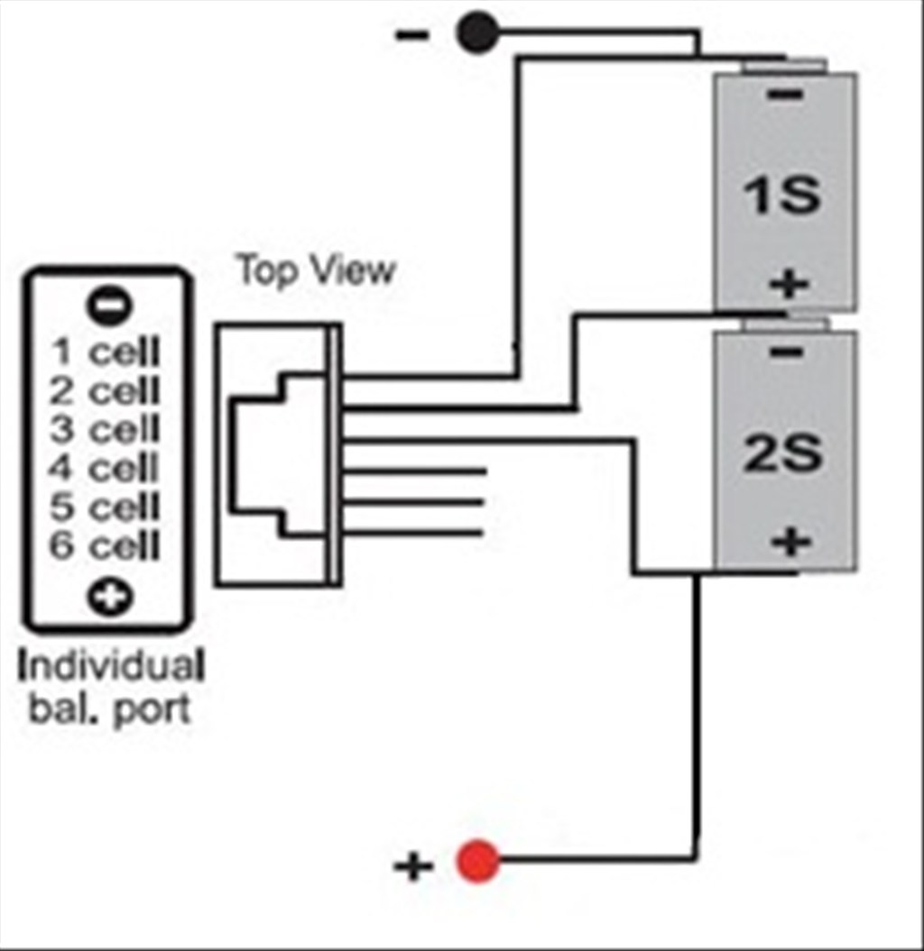
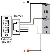
Took time out of building to play around with the battery monitor for the auto charge function. The LiPo battery I am using has a balance plug which is there to give an equal "balanced" charge to all cells of a LiPo battery.
My battery being a 2S LiPo battery has 2 cells wired in series and the balance plug is a 3 pin plug which connects to the + of cell 1, - of cell 1/+ of cell 2 and - of cell 2. I thought it would be ideal to run a cable from it to the ADC ports to read the voltage, what I forgot is ground, being - of cell 2, and cell 1's connection give the voltage of both cells, 8.4v, which is too much for the ADC port.
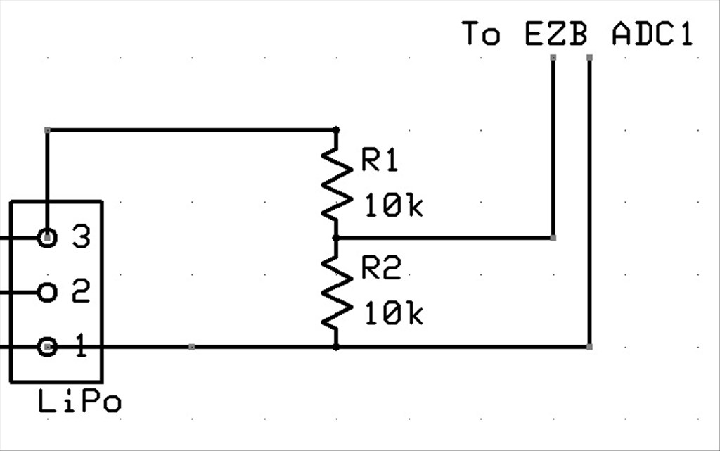
The LiPo battery is wired like this;
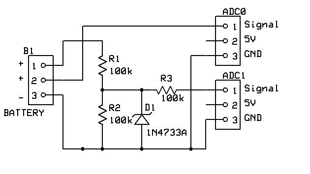
So I now have the first cell wired in for monitoring by tapping off the ground and +v from cell 1. I need to do cell 2 which would be between - and + of cell 2 but the question there is, is it safe to connect the ground from an ADC port to between the two cells?
I also spent some time writing the EZ-Script for monitoring the ADC ports, converting the ADC value back to a voltage value, checking for errors with cells reporting 0v and ADC of 255 (i.e. not connected), and also added in a multiplier for voltage division if required after some discussion here.
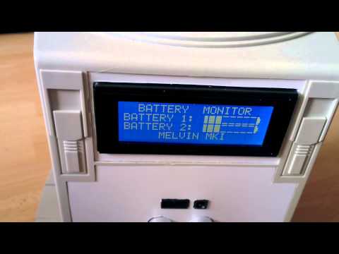
I also made the Battery Monitor EZ-Script available on the EZ-Cloud if anyone needs it (or wants to give me any constructive criticism.
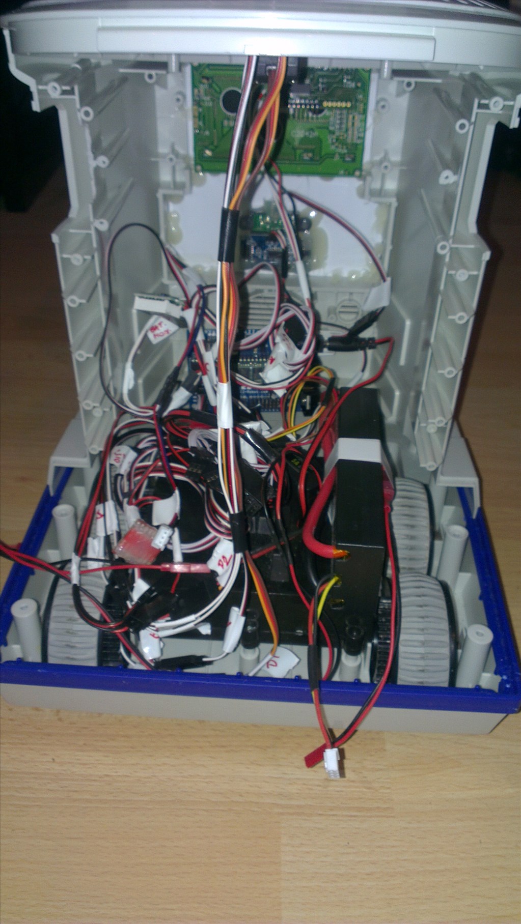
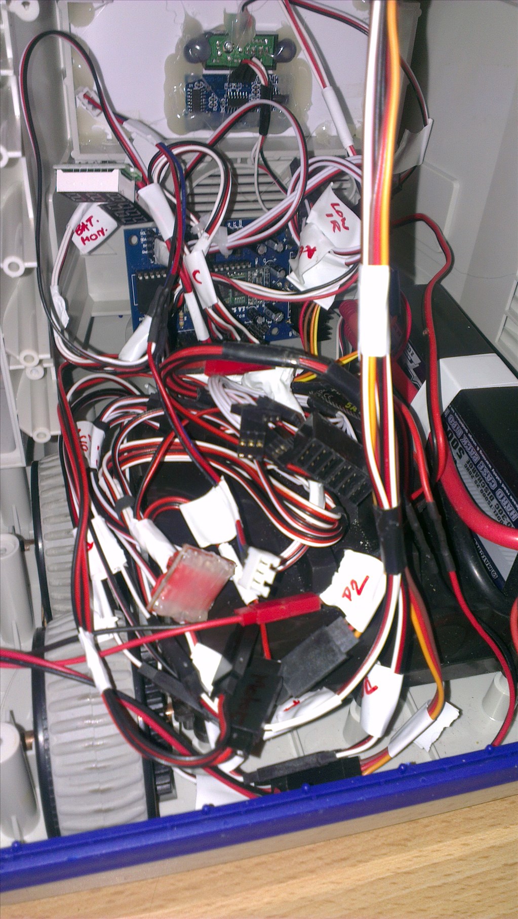
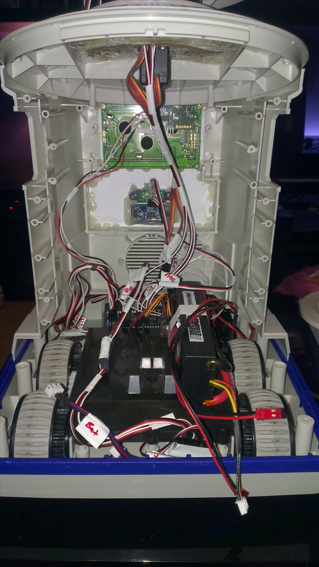
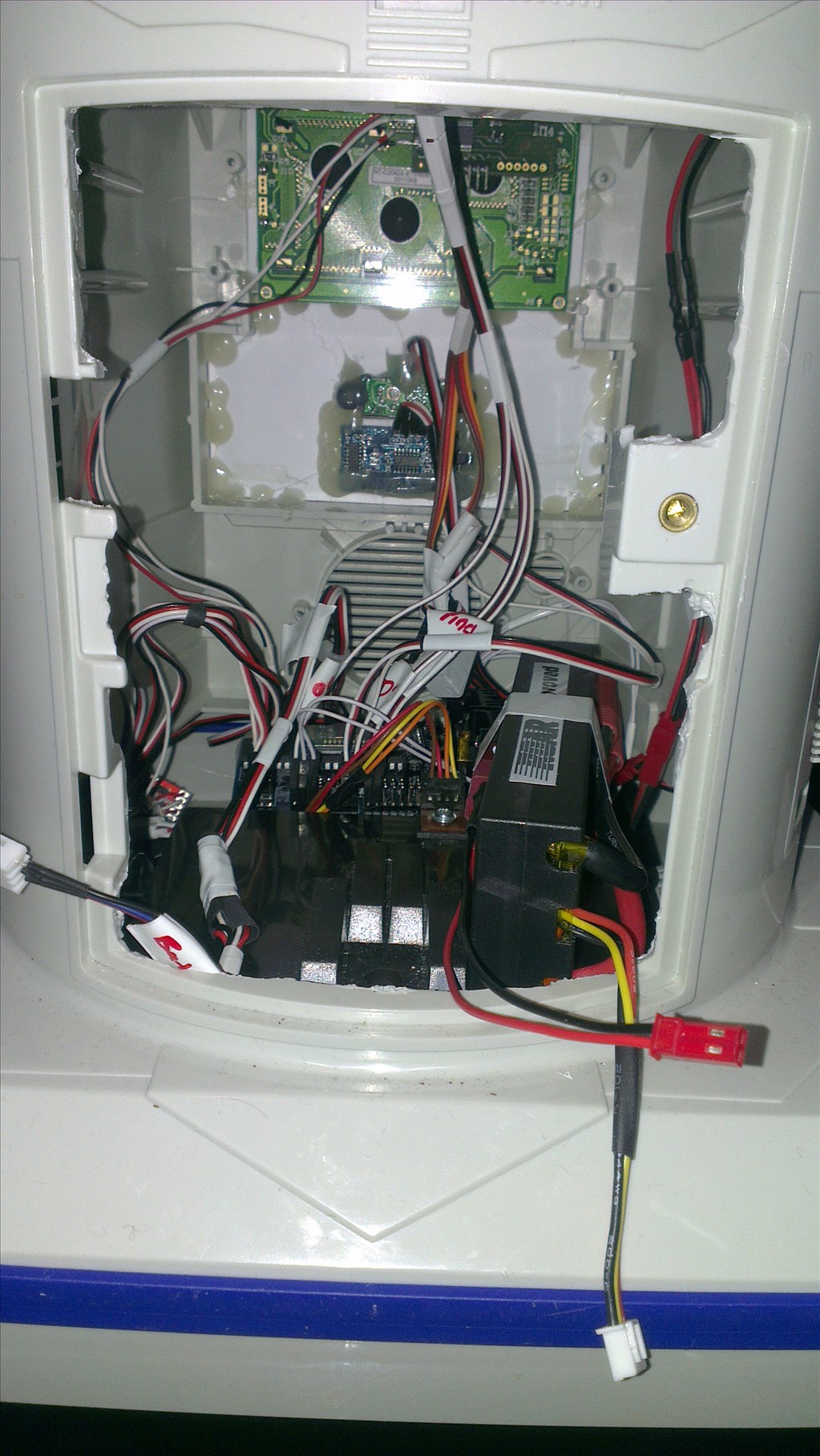
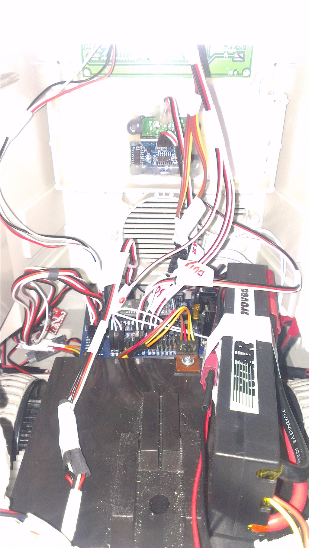
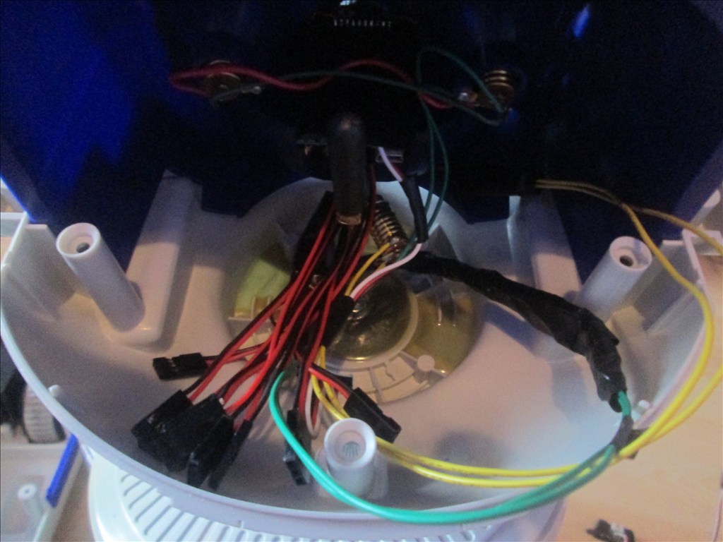
Now there is a mass of wiring to be tidied up in the torso. Some photos
After a lot of googling for my LiPo voltage monitor I finally found the solution, although it's not what I wanted but it'll do.
Seems like the only way to read the 2nd cell's voltage (and 3rd, 4th etc. if more cells if anyone else comes across this and uses a 3S1P LiPo) is to use a voltage divider, measure, multiply in EZ-Script, minus cell 1 voltage and you're left with Cell 2.
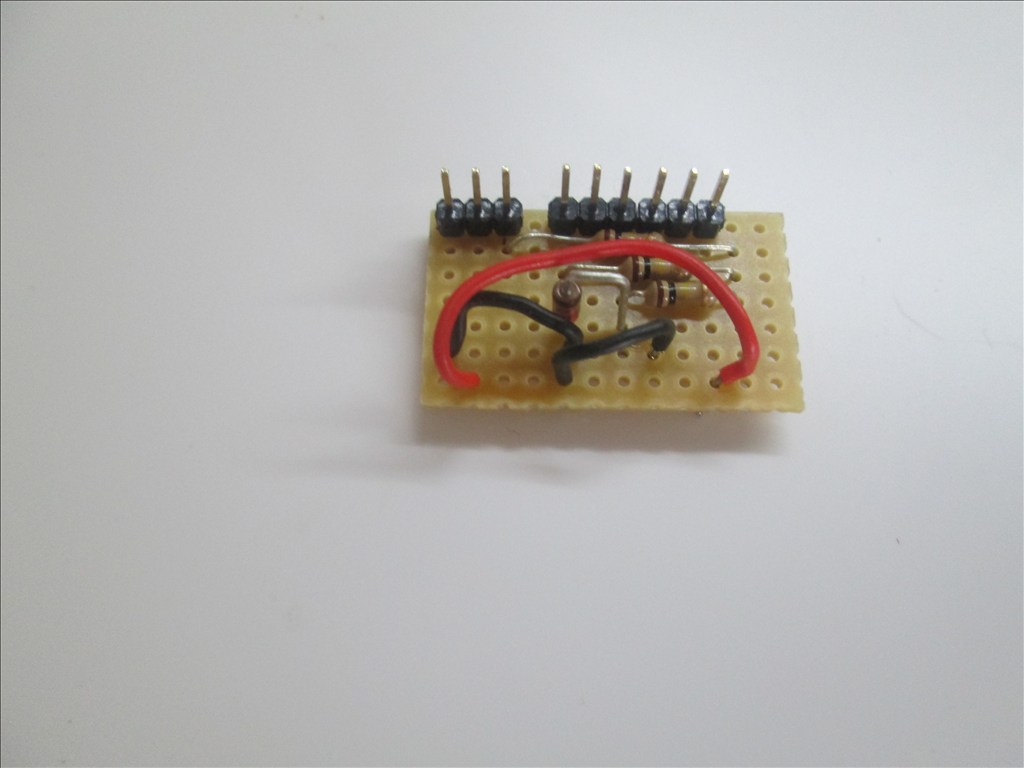
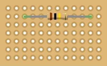
So, now to build the simple voltage divider circuit;
10k resistors are shown as I have those here, is it worth upping them to 100k? Any other additional safety precautions that could be put in place? These simple dividers are all over the net as the easiest way to do it so I assume they are good to go?
And adjust the script, which wont be hard at all.
Nice
As long as the 10k resistors drop the volatge to below 5 volts and using 1/4 watt you should be good to go. Of course a VOM should confirm the voltage before terminating to the EZ-B.....but try and get confirmation from others
I just jumped in and went for it, it works fine It's reporting back pretty much the same as the lipo voltage meter I have so it's all good, although the next task is to figure out how to limit the decimal places, currently they are showing in ARC to too many decimal places, I want it to 2, but that's tomorrow's job.
The total the battery can get to is 8.4v (4.2v per cell) so just halving the voltage did the job. When I get chance I might pick up some bigger resistors to reduce the current draw, for now the 2 10ks wil do though.
better idea is to use a divider for each cell and have analog switch using digital output pins like the 4053 series called multiplexer/demultiplexer chip
with your circuit idea where you say minus 1 cell,each cell has a different voltage as it charged or drain in a robot,so it wont give you a good reading of the second cell
Rich! good to hear(oid) about your bold leap working out! I am thinking the issue of "too many decimal places" is task for ....DJ...unless there is way in your script to strip the extra places.
It gives a spot on reading of the second cell, or at least it did for the 20 minutes I spent testing it.
ADC0 reads the voltage of cell 1 ACD1 reads the voltage of cell 1 + cell 2 So ADC1 - ACD0 gives me the voltage of cell 2
What advantages would the multiplexer/demultiplexer chip give over the resistor divider?
@irobot58 I'm sure DJ has implemented functions in EZ-Script to round off the values to 2 decimal places, I just need to read the manual
you still need voltage dividers,but only one is needed ,way i do it is on your circuit i would use 3 resistors and using only one analog port and would be able to read all 3 voltages using only one porT.
I guess most guys only look at 3 1/2 digits accuracy ,with me i look at about 8 1/2 digits just some thing i i am use to doing. SINCE i have made test equipment of to 24 bits and more robots i guess dont need it since only the A-D is 10 bits ,
BUT how i design my robots ,voltage or current or temperature and more
on resistors for the divider you dont want to go too high,mostly noise ,but 200k total may work
ALSO if you notice i look at noise in the system ,it can cause problems like random resets and more so i use whats called SPG (single point ground ) or wire i try to keep short and twisted oon keeping wire short you save some current ,longer the wire on power you add more resistance where if you do ohms law and wire gauge resistance you will see power loss might not be good at programming but more of a expert in this field
I don't see the benefits of having the voltage monitored over one ADC port, I have 8 ports and only use 1 of them (possibly 2) leaving 7 (or 6) for battery monitor.
There is a reason why I will be rounding it to 2 decimal places, so it looks right on the LCD display. It's an 8x2 and 2 decimal places like "C1 0.00v" takes up 1 row.
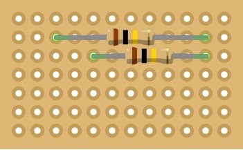
Now stocked up on resistors of all kinds of values as I know I will need them on future projects. So I will be trying the divider with a couple of 100k resistors, might try a third 100k on the signal wire to reduce current draw too.
Also threw in a couple more IR distance sensors for the front corners of the base, so that'll make 3 IR (2 in base, 1 in chest next to Ping) and use up 3 ADC ports, but that still leaves me with 5 for battery monitoring, 2 already used, 2 for possible future extra battery and one spare.
Should all be with me tomorrow afternoon, then I can avoid doing the arms for a while longer as I'm still not happy with how they turned out (although is the only part of the build I'm unhappy with).
Hey Rich, take a look at how Josh Starnes did his arms on his omni 2000. After I saw that I wish I had done it with my omnibot (my servo stcks out at the elbow and is not very flattering - but it works great!).
I'll take a look.
The problem with mine is the buzz from the servos when they are fixed in position so it is to do with the weight and servos. As they are the highest torque mini servos I could find and running with 6v I can't go better.
Plus they are a little floppy at the moment as I didn't want to fix the servos in too permanently until after painting but I may have to so I can strengthen the arms...
It's something I need to do a lot of thinking about and always knew I would.
The other issue is rotating the claw hand. Other than the fact I fixed the wrong hand on the wrong side (not a problem, it works), the open/close mech for the hand goes in to part of the hand assembly that I cut off of the other side to make way for the servo and horn. It's either lose the open/close or lose the rotation. Tempted to rob a hand from the omnibot I picked up as a donor for parts but he is good condition and works so it is a shame to ruin him for a hand...
My main challenge was to make the elbow move without a servo showing and I managed that, I just need motivation to get going on it again.
On my omni I replaced the original opening claw with a metal one and was able to keep rotation claw
But I have buzzing issues too. I think it is a problem if there is a load on the servo and it requires some voltage to maintain position. A little shock (like from an RC car) might work to help support the arm so it requires no voltage at a resting position. THat is the idea I am toying with.
Yeah I've thought of some kind of spring to help against the effects of gravity, I may also remove as much plastic from the inside of the arms as possible to reduce weight as much as possible (plus all the hot glue in the hand that was used as a temporary measure but ended up being permanent), I know it wont be much but it will all help.
I saw your claw, that was an idea also but goes against my whole idea of keeping it as close to original as possible. I did also have a few ideas of some hands, like the toy robot grabber hands with the mechanical handle that pulls a wire to close the hand, I saw one wired up with servos and impressive is an understatement (I may have seen it here?..)
when i have time will look at one my hearoid like your and since i design arms May be able to help build a better one,i mostly spend over a few months just designing arms
The idea is to keep it as close to the original as possible, using anything but the original arms will throw that totally out.
It seems the buzzing is louder as the vibration is being amplified by the plastic where it's all a little loose still, I plan to firm it all up at some point which will quieten it all down a fair bit. I know the servo positions to move it to before release so it sits nicely too so the noise would only be when the arms are doing something which I can live with.
Now it's just the claw hand to deal with but if it comes to it I'll just make it so the claw doesn't lock open and it should be fine.
thats very same on my projects,like the omnibot 2000,i keep the hand just way it is
building your own gear boxes like i do ,you get higher torgue and using less or the same space as a servo,and has RC input
One thing you could do on the servos (aka josh) is use dynamat sound deadening mat on the servos. I used it for the arms in my mini-B9 project and it really helps.
I never thought of that. I need some for the drive gearbox so I'll give it a try.
Yea if you get name brand dynamat its even better that "peel and seal" roofing product. You can double the layers as well. I would send you some Rich but im out myself. I sent a few squares to gunner and Bret who both had good luck.
Don't worry about it, I have some already Josh, I've used Dynamat in my cars on many occasions and have a load of small offcuts which I expect will be perfect.
I am not familiar with Dynamat, is that an automotive product? servo buzz is really annoying. I was thinking of using a building product called "blueskin" which is a waterproof material to go around window sills. Or what about using a heavy internal greese,....any thoughts Robotmaker " thats very same on my projects,like the omnibot 2000,i keep the hand just way it is
building your own gear boxes like i do ,you get higher torgue and using less or the same space as a servo,and has RC input" I would REALLy appreciate knowing how you make your gears, or a how to link! Thanks so much!
Dynamat is sound proofing. As far as I've been told it is the best of the best out there, or so the local car audio centre told me. It's used in cars to reduce road noise and to improve audio quality, I assume by absorbing the nasty vibrations through the chassis although I really have no idea. It's sticky backed, so a nice easy to use peel and stick solution too (at least mine is sticky backed, you may be able to get non sticky).
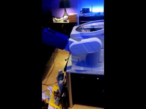
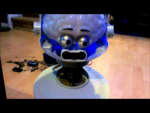
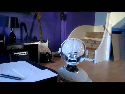
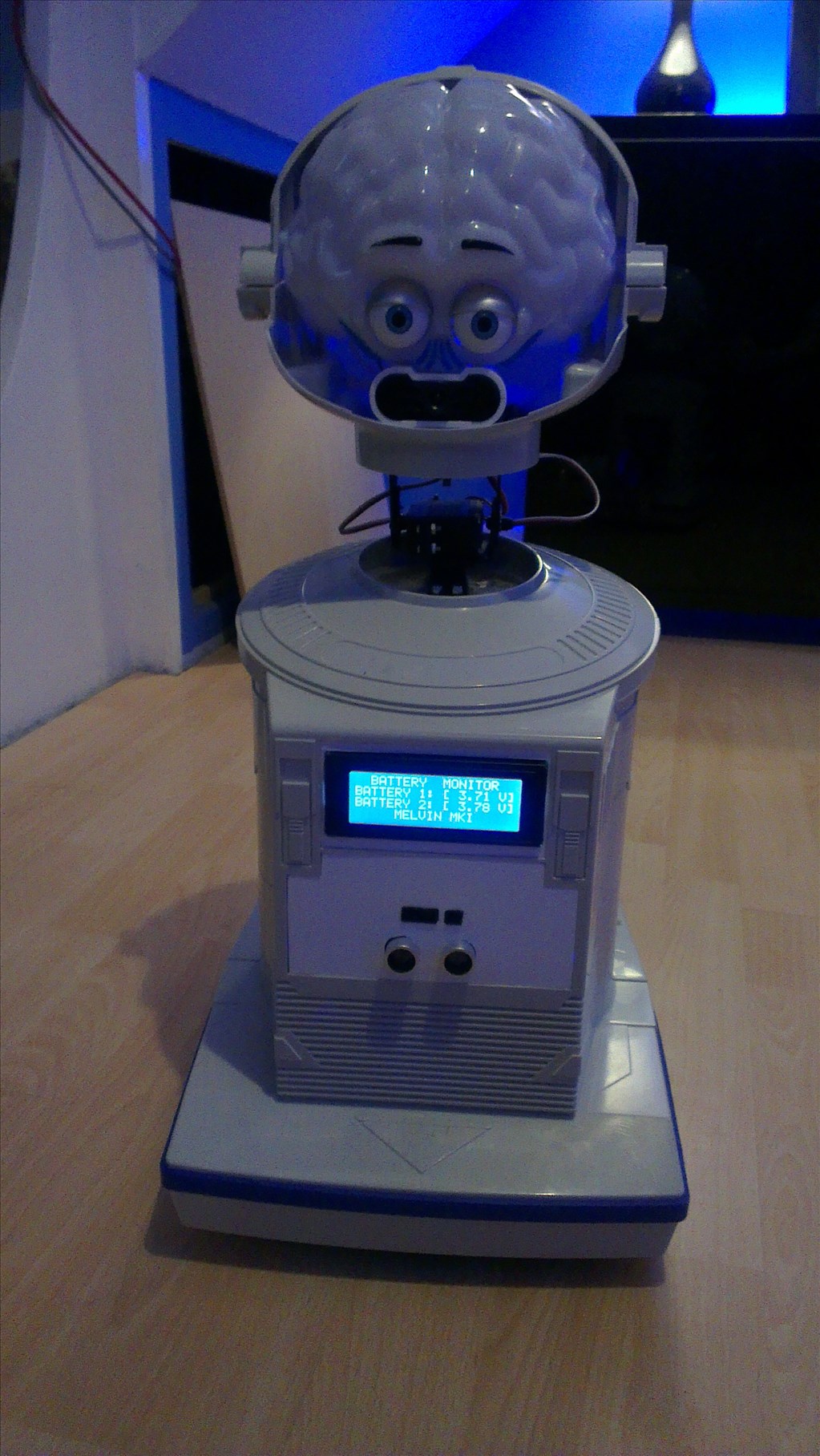
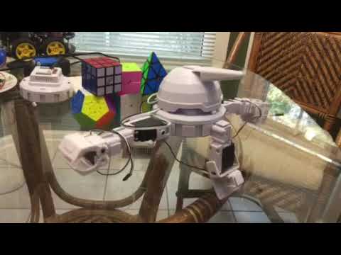
The little fella was sleeping so I thought I would grab a quick pic of how he is at the moment...
I still haven't got around to the other arm yet. I have tightened up the one that's fitted though and the vibration is a lot better. The new servos are here too although I have my doubts that they are genuine Tower Pro servos but we will see how they are when on.
IR sensor isn't staying like that, I was just testing the scripts etc.
And his neck will be covered I was just too lazy to fit it when I replaced the pan/tilt bracket.
Looking good though. Sleepy guy.
@Irobot only put grease where grease goes. Inside a gearbox. Only use lithium grease as petroleum based grease cases plastic old gears to become brittle. Yes inside a gearbox it can reduce noise. One thing ive tried is usinf analog servos over digital in cases where I want them very quiet. They don't make nearly as much racket and practically silent with dynamat. -Josh S
HOW to check the IR without a display tester like arduino ,on the output pin place a meter and to gnd ,place a dark item in front of it ,if it show voltage ,check little far away if it does more voltage then its good and EZB script not working or connection.
Aw don't they look cute when they're sleeping?
I have 2 of them ,so 1 i am going to restore to perfect condition ,on the other one will look at rich and others who made one and how i will make mine and changes
I see most of us like to make our own creation design and use some ideas of others. All of us likes to be different in our designs
I just love the way his head naturally drops slightly to the right when power is killed, I guess the weight isn't balanced but I like it like this so who cares
@robotmaker, I wasn't testing to find distance, I was testing my IR collision detection script to see if it works. The value returned to the ADC port on this IR sensor fluctuates by 1 or 2 when sitting still so accurate distance measurements wouldn't be advisable, but all I want it to do is know if something is within a few inches or so of him.It should be an 80cm range, so an adc of 255 is 80cm or above, or a factor of 0.3137254902 if I wanted to go down that route.
@Josh, I may look in to analogue servos if that's the case. There isn't much space for Dynamat in the elbows without restricting movement so none is on (yet) but having fixed the servo in properly now and closed the arm up nice and tight it's a lot quieter, I'll just have to avoid the servos as best I can when it comes time to paint it.
Just testing the charging circuit now as the battery finally dropped below 3.5v on one of the cells, but with the 800mA balance charger on a 5000mAh battery it's going to take some time (and to think, I am tempted to fit 4 more of them...) I may need to look in to a bigger charger as it can be safely charged at 6 times what I'm charging it at. But that's extra cost that I want to avoid. He was only supposed to be a cheap build and so far it's gone 3 times over budget (my fault for buying cheap rather than good).
it seems you may have on thats not great.ones i have dont fluctuates,maybe because i added a filter you said it not working,way the sensor work is distance and thats only to check it
One you have might have a long distance measurent,if you need to pick collision close you need to get another type
I use different IR sensors for different detecting this is witch one you need for 10 cm to 80 cm GP2Y0A21YK
The ones I have work fine for what they need to do. They are close range proxomity sensors.
I also got the details completely wrong, they are 4cm to 30cm so the factor is (30-4)/255 so 0.10196078431. I only need to detect a few inches at most, so around 10cm which is well within the range. I may have got the ADC value backwards too, I'm not sure without checking.
They only fluctuate over long distances and I assume that's down to the distance, light and probably a whole bunch of other factors.
The data sheet is here
The 10cm to 80cm aren't suitable, I need less than 10cm as a minimum.
@Rich Its interesting how humans "personify" inanimate objects( ships are a big example and sometimes computers/programming)... and yes I too liked Hearoid's sleepy posture, For those of us who have had children, it reminds me of my little ones falling asleep in their high chair!
I really like it Rich, when you present the " ooops's/errors" of your builds because two reasons , it shows how human you are with ego not in the way .....and ...we all learn from errors as well!
@robotmaker and yes I agree ,everyone like to have their own design (wait till you see mine) very much like a Zoo or peoples plates at a smorgasboard
and yes I too liked Hearoid's sleepy posture, For those of us who have had children, it reminds me of my little ones falling asleep in their high chair!
I really like it Rich, when you present the " ooops's/errors" of your builds because two reasons , it shows how human you are with ego not in the way .....and ...we all learn from errors as well!
@robotmaker and yes I agree ,everyone like to have their own design (wait till you see mine) very much like a Zoo or peoples plates at a smorgasboard Breakfast time ..I am getting hungry now!
ok you said you needed at near 80 cm you needed to detect thats the reason i bought it up and you said they wasent working and not stable
also i dont know if you know this but one thats analog is mostly for distance,not collision but still can be set as one ,digital ones mostly for collision
@irobot I will be honest, this forum is pretty much the only place my ego doesn't follow me, or at least I try to keep it in check but this is also probably the only place where I see people who are better than me.
@robotmaker, that wasn't what I was saying but the advise will be useful in the future. I've added the one you suggested to my shopping list for another project.
soon then i get my optical bench finish and to help others besides you will put info up on all types of IR'S plus how to make the very stable,they mostly need a simple rc filter.
Need to get parts in and mill them for holders for different sensors and materials.
Awesome contribution robotmaker! A data sheet for various sensors!
i have a keen eye on your topic about the sensors as my big build will need a lot of them for sensing different things, different distances etc. It looks like it's going to be using at least 3EZBs for the servos so that's 30ADC ports (although some will be used for monitoring other things).
But that's not Melvin the Hearoid, Melvin is simple and only needs to detect objects just before he crashes in to them or detect people getting too close. The sensor I used does that very well (I have 2 more to fit to him yet though plus the sonar ping/echo sensor)
i desgn circuits to use only one EZB and many analog ,or digital or servo's
I read through your posts and I had a couple of questions:
Did you need to use high torque servos for your robot's neck?
Can you post of picture of the +6v board you referenced on this other thread: High Power Servo
I'm rebuilding a Robie Sr, so I'm very interested in your build progress.
The neck was a bit of a nightmare but only due to the height it added (and still does). I tried mini servos and the mini servo pan/tilt bracket but it wasn't anywhere near good enough. So I upgraded to full size and had high torque servos in there (although running from the EZB power not 6v). It's something I want to go back to and try to get the height down a little although it's not that bad.
Servos in the neck are Tower Pro MG995.
The board I referenced to in the other topic is very basic... A small piece of strip board (not sure if that's what it's called over that side of the pond), 0.1" spacing with a copper strip from one end to the other on each row. I took a few servo extensions and cut the red and black from the male end, soldered these to the strip board and left the other end so the servo can plug in. Male end plugs in to EZB to give only the signal wire. Power board supplies both +6V and Ground to the servo (or female end) I soldered the +6V and Ground from the 6V regulator to the strip board which gave one row +6V and the other Ground. And viola, basic break out board for 6V.
I would post photos but I never took any and it's currently buried deep inside Melvin.
Arms on the other hand need High Torque servos and +6V to lift and hold without too much struggle. I haven't finished the arms yet as I am not happy with them but the servos now do as good a job as can be expected.
Elbow joints were high torque and +6V mini servos. These still struggle at certain angles.
Hands are just cheap and nasty (suspected) knock offs, they are fine.
Perfect description, thanks!
If you're looking for a new neck bracket, I purchased this bracket from lynxmotion. The tilt range isn't very steep, but the gap between the base of the Robie neck and the shoulder is only slightly more than the height of a servo. I'd estimate about 5 to 7 centimeters altogether, but that's just from memory.
That's the bracket I have on it at the moment. I did have it with the long c bracket to begin with but replaced it for a short c at Christmas... it's still quite long.
I am playing with the idea of fixing the tilt servo flat to the base of the neck, fitting the pan servo to the tilt (with a hole cut in the base of the neck assembly to accommodate the tilt motion) and fixing the head to the servo horn of the pan bracket (if that makes sense). I think I posted a quick sketch some time ago (so back a few pages) of that idea... But it means cutting the base of the neck which I have trimmed down and filled in with fibreglass so am trying to get to like the slightly longer than it should be neck.
The other idea was to cut out all of the part inside the base of the neck (hopefully you know the part I mean) and have the pan servo lower down inside the body of the robot.
I know exactly what you mean.
Your idea in the sketch may limit your head movement...or at least make it a little awkward. If the tilt function is mounted to the body, then you'll be limited to only having a tilt along the forward facing, center line of your robot. Your robot will have a hard time seeing below/above his left and right shoulders and maintain a horizontal based line of sight. The tracking grid lines on the camera views may not function for you if you pan the head rather than turn the whole body.
I may not be describing this very well.
I understood it, I'd thought of that which probably helped understand it a bit. It's one reason I've not changed the neck for 2 months. I've learnt to deal with it the length it is, and it's a lot better with the short C bracket rather than the Long C bracket, although the bracket hits the servo but it makes for a nice stop to save the head leaning too far forwards or backwards and doesn't damage anything.
Was just wondering, did you get a chance to test out your original plan to have him move around by him self or did you move off that idea an into another?
He moves around by himself.
I've changed sensors more times than I care to remember but currently (and may change again depending on the auto charging solution) he runs with the Ultra Sonic Ping sensor in his chest area, a short range IR sensor in his chest, another IR short range low down (just above the blue bumper around the base) and another IR lower down angled at around 60 degrees to detect anything lead on the floor that may be run over (cables, rubbish, etc). These allow for him to free roam, move through doorways and avoid any object in my house.
I may also add in another IR sensor on the back just above the blue bumper for when reversing.
Then a simple script which loops around a forward command with checking the ADC ports and stopping, reversing, rotating and moving forwards again.
Tied in with the Personality Generator he also randomly does other things like dances (not perfected, he has no arms), looks for faces, nods, shakes his head and a few other things.
Do you plan on using the 3D map at all with him? I was thinking that I would use a helicopter with a wirless camera on it to fly around the house, map the house, have this stored onto a hard drive as a GPS for the house. He would fly around every so often or if a robot gets stuck or lost, he could fly to its last known location in memory, and dispatch the updated map to the lost/ stuck robot. What is your brain space on this, is this doable in your opinion? I have yet to learn even the most basic scripting/commanding, so if to you that's just not possible then I'll just scrap the idea.
No. A 3d map would take a lot of work to integrate with ARC and on this project I cannot (or will not) spend that much time and effort on. Possibly future projects may use something like a 3d map but not this one.
Something like that would probably require using the SDK, which I am not familiar with. Learning C# is on the to-do list and I have brushed on it briefly but other training takes priority (I am always learning something new which explains why I seem to know something about everything...).
Honestly, I would work your way up to that project. Start small, learn, go bigger, learn more, go huge That's my plan, this is my first project, others are planned that do more and more things all eventually leading to my big build (life size humanoid robot - years away from that!)
Everything is doable, just some is not feasible.
Thanks, I'll do my best to contain my imagination, lol. Looking forward to see what more you will do Heariod here. Anyway, I do believe it is 2:00 AM, good night.
It's 9:30am here, I can only wish it was 2am again and I wouldn't be sat at work
Adding a map it a great idea ERRUEL ,great for full autonomous robot independance ,witch i like using in all my designs
Only problem is making the map and the time and scripting,i havent look in to it yet,but will very soon
I thought EZB has a map built in,going to look at it EZB floor map
doesnt say if its a 3D MAP ,MOST LIKELY NOT,and no info on how to make a map like other software has.but may be a video on it
The Map in ARC is just a record of where the robot has travelled and will not do what @Erreul has mentioned. It is not accurate enough. The value also differ depending on what surface is being driven on etc. It's based on time not on distance.
I am thinking not about ERREUL idea,but using it with other sensors to map a room for navigation.
So far you adding those sensors in the #1 of this page looks kinda good.
but would be good to have the same on the sides both IR and sonar and 2 at a angle in the front and small cone detection,main reason is to use for detecting wall corners
IF you dont like the idea on your project its great,.just a idea for others
I have no need to detect wall corners. There is no reason to add any sensors to the sides and doing so would go against the design spec of keeping it as stealth as possible.
Not to mention, I am using almost all digital ports already, plan to use all analogue ports and this project will only be rocking a single EZB so adding in any extra sensors is a no go. Also checking that many sensors at a usable speed would bog down and flood the communications between the EZB and the PC, increase the CPU usage and has a possibility of causing major slow down. Checking every 50ms for 8 IR sensors on the ADC ports would be 160 checks per second, when I ran the benchmark I believe (from memory, I will check again when I feel like it) it managed between 70 and 80 per second so would have to be dropped to 100ms between checks for starters and that doesn't take in to account the added stress on the CPU.
Might as well skip pages 15, 16 & 17... skip to page 18
Ok great only a idea,others looking at your build may need it,
Doesnt hurt or matter to me you dont use it,ONLY A IDEA to help you out.
i found ways to add more analog and digital ports without another EZB ,looking to post my design up in a few days and its under $1.00
Unless it also improves the communication between the EZB and the PC then it will be of little use. sleep
It will be the same communcation .only uses one chip with up to 16 analog and another chip up to 16 digitals using mostly one analog port and 3 digital ports for control lines ,so speed stays the same so you are looking at total of 23 analog ports ,with 3 address lines
I hear some using up to 3 ezb in one robot,thats a big waste of money each board is about $70 ,compare to a part thats $.50 PLUS A SMALL PCB FROM RADIO SHACK thats all s needed no other parts.
WOW for once we are not arguing ,thats a first
Yes, I was about to comment that you guys are acting civil. Congratulations, maybe you two can work together to make a super robot.
Thats what i am trying,not looking to arguee and hope the same from RICH,if he doesnt think my idea is good or disagree with me no problem. still think i am correct
I will only say i disagree
I remembered a company who make custom front panels so plan to use them for the front panels of this bot for a very nice, clean, neat professional finish.
http://www.frontpanelexpress.com/
Now I just need to finalise what will be on the front panel and get it designed
P.S. I would never work with robotmaker, it is hard enough ignoring him, as stated elsewhere I will no longer be engaging in any conversation with him for reasons which are obvious. I have not said this to be nasty or to offend, I have mentioned it to clear it up. This paragraph needs no replies, but I'm sure someone will take offence despite that not being the intention.
I feel the same way too,anytime RICH says something about my ideas that DONT NOT WORK best is to just ignore him and say "you say so" and let OTHERS try my tests
BUT last comment i will make on this post ,he cant tell ME not to post about any software like robnorealm,if he doesnt like WELL TO BAD
HE cant keep me from making comments on his posts,and same i cant keep him from making comments on my posts
RICH doesnt want to work together ERREUL thats just the type of person he his
I know RICH he will comment on this
I USED frontpaneldesigner before,my company i work for had many panel i came up with,prices are high but job is good
ROBOT's most of us make dont want to put much money in to it,look at the post on the home base finder,everyone looking for a cheap sensor.
ME i may use it,since i can get a discount and money not a problem.
But depends on the robot design,any time you send to have a company to make custom parts,platEs or PCB'S its going to cost a lot,but if you have a good machine shop you can do it cheaper
Useless post removed
PLEASE IGNORE RICH,look at the prices first then compare results,many other companies make panels and i think most everyone knows anything CUSTOM cost good money,they some on this forum does not have .
do COMPARE PRICES first and see if it fits in your budget
he SAID i dont want to help,read my other comments on helping him with adding other analog ports and the idea i had for adding a sensor
RICH is the type of person who is a angry guy,if you read is other comments on me from others posts ,"saying cant wait to rip my head off" other bad word H**l and other comments
NOT once did i say any of thoses or anything badmouthed
MY my claims are true,did some i test and best thing advice to i give to others is compare or test Onthing i am not good at is programming and windows 7 software,so wont make any comments on them
REPLY AGAIN RICH like always
@EMMEUL as you can see i try to be nice to RICH in a few comments above about some idea for his project,i just could not be a nice guy and not give him any idea's ,but i was a nice guy and tried to leave what happen in past be gone
But as you can see he spit back in my face saying he didnt wont to work with me, so i guess who you can see who is a nice guy and who is not.
SO just the fighting will go on and on
Useless post removed
LIKE i said i cant make any comment on your post if i want,you cant stop me
like you said you will make comments on my posts.
I can do the same also RICH have you removed from making comments on my posts too.been windows 7 post or any other posts software or hardware.
BEST part the EZ-ROBOT team wont like are you bad comments against me,its in the rules also ,no bad words or comment the hurt others like "like you said cant wait to rip my head off"
the EZ-ROBOT team wont see any posts of mine like that
YOU can use the company if you wish also.
And in the post on your design they will see also i tried to be mr nice guy and put the past in behind and tried to help you. I WILL IF I NEED TO REPORT TO THE ez-robot team too
BEST idea i have for you dont not reply to me and i wont have to respond back,very simple
Useless post removed
Any way guys on the the custom panelboards,some good advice check other companies who make them and compare costs first.
My company uses the one rich mention,since i make in house test equipment to test the products before they get shipped,pcb testers,production testers, and qc testers and i have a lot of panels made well over 300 panels only reason we use them,
My company i work for they make 10000 panels for us a month,so when i order one or 2 panels for one tester ,cost very low and sometimes they do it free.
But when we have a panel made for one robot ,cost will be very high ,plus shipping
I see a few guys here make there own panels or decals there self ,so thats another way to save money too.
SO compare your costs first and see if it fits your budgets
As it was asked in this topic and I've just sketched it for another topic I might as well add it here too.
The external power board for servos needing 6V which I described, very simple and works great.
Snip off the red & black from the servo extension which plugs in to the EZB. Solder them to 2 tracks on the strip board. Solder the 6V supply to the strip board (not shown) Viola... 6V power distribution.
I have a PCB design which includes a 6V regulator but it's at work, I will post it on Monday if I remember and have chance.
On my board I left 2 rows between the VCC and Ground in case of sloppy soldering.
I also used a 5A 6V regulator to supply the board with a steady 6V.
Thanks, Rich. Easy to understand.
On the regulator here is the specs unless the company who makes is wrong from the one you posted
?Input Voltage - 6v to 25v ?Output Regulated Voltage - 4.8v ?Output Amps - 5A ?Weight - 19g ?Size - 20x14x49mm
it says 4.8 volts regulated so doesnt supply a steady 6 volts CHECK THE LINK IF YOU THINK I AM WRONG
Once again, please check before posting incorrect information rather than pouncing on any reason to put me down.
This has also been confirmed by my voltmeter and the following websites;
http://www.jemodels.com/nitro-models?page=shop.product_details&flypage=flypage.tpl&product_id=11599&category_id=248 http://www.cmldistribution.co.uk/cml_product.php?productId=0000005987 http://robotbirds.com/catalog/product_info.php?products_id=1324 http://www.ebay.co.uk/itm/Etronix-LiPo-Regulator-6-0V-5A-/310562839591
RICH is so smart guys he changed his link,so at my info posted you can see it camne off his link he had before,on the new link he changed is NOW CORRECT
WOW guys he wnt very low on doing this
here is the real link he gave first http://etronix-rc.com/etronix-li-po-regulator-6-0v-5a-w-casing-20x14x49mm and specs on it too
This cunning little unit allows the use of any battery from 6 to 25 volts to run your RX pack.
?Input Voltage - 6v to 25v ?Output Regulated Voltage - 4.8v ?Output Amps - 5A ?Weight - 19g ?Size - 20x14x49mm
NOT right to call people liers RICH only open your link and posted the info i saw thats all,,didnt check with a meter only copied and pasted it on my comment all
Maybe he posted the wrong link by accident. Its not a big deal.
i think i might of done that ,that not the problem he said i was wrong
Useless post removed
I think the company is wrong on the info too.since i look at ebay on etronixs, Only i did was to look at the regulator for my design ,like anyone would do and when i saw it had a output of 4.8 volt
I just posted the info for others, to check the same If i didnt post anything i think someone would find the same link and said something too
I always check my specs first on any part first,i know companies posted some info wrong
GOOD that RICH correct the link also
I DIDNT post incorrect info (but to me it seem like i was lier) I posted your post link and what the website says ,so its no incorrect like you say
very simple is i didnt post it,someone would go to your first link and saw the link too and saw the same info as i did
OK since the regulator is good one and info is fixed,i ordered 5 of them for my designs.
i guess i could easy found one like it ,
But good for RICH to find it
IT same me some time
LIKE i said in a few posts not looking to argueeor fight with RICH any more
Only click on the link and posted what i saw ,is all i did
Useless post removed
ok sleep
Since pages 15, 16 & 17 seem to have gotten filled with some trolling etc. I will repost the useful post in the hopes that it doesn't end up being bogged down with rubbish again.
As it was asked in this topic and I've just sketched it for another topic I might as well add it here too.
The external power board for servos needing 6V which I described, very simple and works great.
Snip off the red & black from the servo extension which plugs in to the EZB. Solder them to 2 tracks on the strip board. Solder the 6V supply to the strip board (not shown) Viola... 6V power distribution.
I have a PCB design which includes a 6V regulator but it's at work, I will post it on Monday if I remember and have chance.
On my board I left 2 rows between the VCC and Ground in case of sloppy soldering.
I also used a 5A 6V regulator to supply the board with a steady 6V.
THERE is a easy way to do that too,a barrier strip or power lug strip and it has holes to mounted to a case or inside a robot
For Christ's sake... Could you two refrain from this crap? robotmaker, refraine from posting to Rich's posts and comments and Rich do not post to robotmaker's posts and comments. You two are both grown God damn adults and I wouldn't mind if you started acting as such. I don't care who is starting it, or if you guys need to make a certain post to rip on each other without it spilling everywhere else, but get it squared away. I'm not just saying this because I'm tired of this bickering, but because the community is aswell. So, just don't associate with each other, period, don't correct each other, alert another member. Both of you are smart people, so lets agree to disagree and cut some losses here. No childly "Yeah Rich!" Or "Yeah robotmaker!", lets just move on and do what we love. Robots. Lots and lots of robots.
I do apologize if this has in anyway offended either of you, however I still stand by what I say.
On a happier note: What servo is that attaching to, just the specific ones that need that specific voltage to run?
This board supplies the high torque servos in the arms, giving 6v increases the torque and reduces the humming when holding at specific angles.
JUST posting ideas,just like others do to others posts nothing wrong with that
I dont say anything wrong about his design ,only found a better idea thats all.
IN my last post only said i found a easy way to make one with out have to solder the wires.
Same in my PROJECTS designS if anyone suggest a idea that makes it easy also.
That info i posted was not for arguing or anything else.
One part of this build I was quite interested in was the sticker on the top. Sounds small and insignificant but it will make the world of difference.
The original sticker was a little worse for wear;
So I needed to make a new one. Quite simple really. Start off scanning in the original;
Clean it up and remove everything but the general size and shape of it
Sort out the outline/edge
Add in the robot's name
Then make it look almost as if it was stock (matching the blue of the Hearoid sticker)
Next stage is to print it and stick it. I have ideas on how to achieve this, the first is to use a specialist tattoo paper which is clear but takes ink very well. Until I try it and am satisfied with the results I can't really post the details, but they will come as soon as the robot is painted.
If anyone wants the photoshop file for this, well, here it is... hearoidsticker.zip
This should also fit a Robbie Sr.
I did something similar on my Gunslinger Bob, only I hand cut the letters out of self adhesive vinyl decal material. Not nearly as neat as yours though.
My standards are stupidly high and my skills with a knife are stupidly low (you should see me chopping veg for dinner - I buy it pre cut now...). I did think about vinyl, and it's a back up plan. Luckily I have contacts in the sign writing business I could call on and get the sticker made for cost price but I like to do everything myself where possible. Plus it was fun to design
label you made does look good RICH,me not great at art work
BUT as i see idea that i think is good or better i will post like on barrier strip and why its might be better,not many have circuits to cut ,second hard to mount it
on my idea you unscrew the terminal a little place wire and done.mostly high current and very low cost $1 and they have a strip of terminals at that price and you cut with a wire cutter to size second to mount it they have holes on the bottom and takes little space
Slick idea Rich
I think being a Canadian I try to be a peacekeeper in any situation, haha. I think I remember you posting on Roborad? I understand that the creator did a name as well, did you consider using his process?
See the previous page. It's plan B but as my knife working skills are next to none I thought I'd try this way first. If it comes to it I'll use a sign writer to make the sticker out of vinyl, one owes me a favour or two anyway but I prefer to do everything myself where possible. I know I wont be able to produce the sticker anywhere near as good by hand, for a start the slight gradient on the background blue would not be achievable.
True, that would take weeks by hand, and many frustrating crumpling of expensive parchments. That is from experience.
Not to mention band aids.
BRET did a really good job on the labels in ROBORAD PROJECT
Hi Rich,
Nice job on the robot! Maybe sometime I can pick your brain on some questions I have with my build.
That head is really cool...
Den
From what i see RICH design looks good,only saw a few changes i would make i have 3 of them at home and start on the someday soon,his design might give me a few ideas just i tried ti give him a few.but turn in to problems ,but thats in the past and hope over
@captor03 pick my brains any time.
I've still not finished this build; The arms need sorting and I'm in two minds to change the complete arms to something else or re-fit the connecting links that make the lower arm move. But whatever I do I need to do more dremmelling and create mess. The neck needs sorting with some grey plastic cover, I have white 100mm ducting which I can use if it comes to it but would prefer something more like Omnibot 2000's neck piece. I have some at work on the portable air con unit but it's being used... The front panel needs designing, making and fitting, all should be simple enough to get done though. LCD Display needs sourcing, fitting and programming. Sensors need fixing permanently. Paint needs to be applied. Decals need fitting.
So not much left to do. I haven't had time for any robot building time for about 3 weeks but it'll get there eventually.
Can we see a movie some time soon?
,waiting on the codes from my friends on LIDAR ,second since i dont now SDK thats the problem,but it is so very simple ,and DJ is will be very easy with a C# CODE since SDK uses C# and most the work it done already.
Plus there others who bought one from me to use on EZB and they know it needs a SDK,and most likely they are a programmer
Plus if anyone buys one from me and makes a code to EZB they get 50% back just to speed it up most of it should be very easy since it has all codes and was done easy in ROS
ANY good programmer should be super simple,i think only time holds them back
I can also let anyone borrow my board for LIDAR ,since i bought 2 of them.
@Erreul There are a few videos floating around but nothing great yet. When I get chance (and motivation) to bring him out of the spare room I'll do some videos.
In the mean time;
And
Oops, that last one isn't a robot...
I don't know which one has the smoother movement, the robots elbows, or your moonwalk!
Den
Oh! A wall! Haha. Both look pretty good, the robot and the smooth moves.
I see the camera is very fuzzy why is that and will you post a better one
I see on the head only going up and back so side to side ,dont meen head rotate ,on mine i design it so go up and back rotate 180 and side to side
ON dancing its not a robot doing it,but my nephew is a very good dancer,won a few contests ,but yours still good
The robot eye view video is just out of focus, nothing a quick tweak of the lens wont cure. it's also dimly lit which is sorted with the settings in ARC but video capture doesn't capture processed video only live video.
The head pans and tilts, tilts between something like 45 & 70 (can tilt up to about 95 but that just looks wrong) and pans the full range but I've set it for 20 each way (30 & 70).
NOT about pan or tilt ,just wounding are you going add side to side head tilt
looking to set mine like a person head does ,from shoulder to shoulder tilt down i guess its 45 deg and tilt back about 15 deg and side to side i guess about 30 deg on each side
Does need a post with a ball and socket and 2 extra servos and ball and socket design i have there are other ways too ?.
maybe this one post will explain it better
No, I thought about it but it would be too much effort making it work and having a neck that's not stupidly long (I've shortened it from the video posted) or too flimsy. The head weighs quite a bit, more than I expect it would.
That's what I've tried to replicate, a human head range. It's not 100% lifelike without the tilt but it's close enough that it's not noticeable unless you look for it.
ok just curious havent tried yet on hearoid yet,soon to be another project of mine
mine head doesnt stick up much ,omnibot 2000
IF head is heavy ,see if you can remove any plastic,i do that on mine,and still not flimsy
Few other ideas i keep all servos in the body,and the shaft with the ball is the par thar rotates and the ball moves 360 every way,can hard to expain iy
but when ready if you want to look at will have it up on my omnibot 2000 project
Looking really good Rich. You have made some good progress!
yea I said it too he did do a real good job on it,wish i had more time like he does,but in a month (counting the days) i will
The 6v on the elbows make such a difference, as can be seen in the videos... in fact I needed to slow down the arm servos. Removed the arm again recently though to get it a bit more solid and fix it to the shoulder servo a bit better.
I've neglected it for about 3 weeks now though but hopefully I'll find time to get back on it this weekend and get the sensor mounted properly, fit the servos in to the right arm and sort out the shoulder servos.
I'm really tempted to add a slight riser to the base too, just to give it a little more height so the arms can hang down straight and make the neck look more proportionately correct. What I would love to do is give him working legs and turn him in to a biped but that's a little beyond me at this stage.
BIPED desigh is hard,i ordered a kit with out servos,needs a gyro and more
You should teach it to moon walk.
I plan to!.. I have some videos planned and the frames set up, he just needs his arms before it'll work right
I was bored so decided to move my schematics over to Circuit Lab, and then got carried away by drawings the Schematic for melvin.
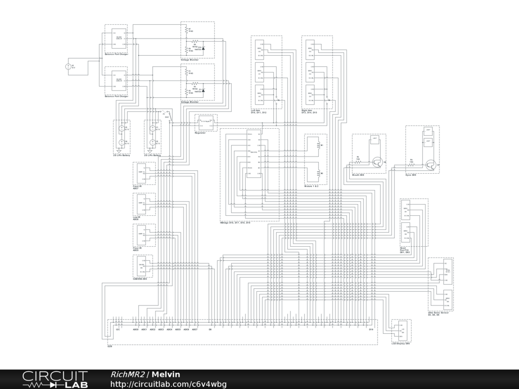
I realise it's probably difficult to see from the image but click on the word Schematic above (or there) and open it in the editor, play around, copy bits, go nutsAs you can see, I have used the EZB pretty much to the maximum possible. I think I have 1 ADC port free (planned to be used for current monitor) and 1 Digital port free. Some things may need to be combined to make way for the possible future MP3 module and 4th servo on the arm for opening/closing the claw.
cant see the schematic very clear ,both clicking on it and the link
You should try pcbexpress its easy to use and imgage can easy made any size ,plus up to 4 layers and then have a circuit board made for it
ExpressPCB costs far to much for one off PCBs, the cheapest is over £175 delivered to the UK, multiply that by roughly 1.5 and you get dollars...
I do use ExpressPCB for schematics but the problem is I can't use it everywhere, this I can hence moving everything over to it. Works on tablets and any PC regardless of OS and all stored in the cloud so it's better than ExpressPCB on that account. Plus you can simulate circuits to make sure they will work, check voltages at specific points etc.
Following the link and choosing Open In Editor, as mentioned above will allow you to view it, zoom in, pan around, copy and paste etc.
But if that's too difficult for you here's a bigger version (click it)

However this one doesn't automatically update when I amend the schematic.OK.expresspcb in usa is super cheap PCB I HAD MADE IS 19sq inches total cost me $89.12 for 2 boards including shipping, 2 layers plus holes miniboard service is 3.25 inch by 2.5 inch 3 boards with shipping and holes $51
plu on the first one for about $89 if you buy more price really goes down alot per board
wow $262 prices are high in UK
WILL TRY the EDITOR
also looking at my pcb i guess i forgot i see its 3.75 by 2.5 inch so if i move the parts together with i can easy do it will cost me $51,i need to do that tonight
Finally got the robot back out of the spare room to do some work on him tonight but that didn't quite go to plan when I checked the voltage of the LiPo and it was 3.6v for both cells... It looks like one of the cells is now under voltage if not both which sucks!.. (I may try a dangerous repair by charging it as an NiMh if I can find something fire proof and am feeling like risking burning down my house)
2 more are on order though. Now I need to decide if I want to rock two in parallel or keep one in reserve just in case I make the same mistake again. Do I really need 10,000mAh of juice?
A small set back and further expense but it'll be worth it. It just means I need to wait a little longer to buy that second EZB for project 2 (details will come shortly but want to finish this one first).
Also decided to redo the small circuits for the switching of the lamps and the battery monitor using some stripboard and adding in the Zener diode to the monitoring circuits (since I had to take the whole thing apart to get the battery out anyway I might as well).
So no new photos yet or videos. But it's the perfect opportunity to make some tutorials on those circuits. Every cloud has a silver lining and all that
I did the same thing to one of my lipos. Try recharging it outside.
Den
Looking forward to it. Wouldn't mind learning everything I can.
You need a special charger for LI-PO ,it needs CC and CV out and a balance board
On the current need its little hard,but a good rule of thumb is find out total current is needed and hours you want it on and add 25 to 30 %
Useless post removed
LI-PO dont have a memory effect,and can keep them on the charger after they are charged ON yours may be hard to tell what happen
If a LiPo goes under voltage charging them is dangerous and can cause fire and explosion, which is very well documented on the internet. Most good LiPo chargers have safety features in to prevent any potential problems.
My chargers, both the expensive all singing all dancing one and my cheapo one refuse to charge the LiPo. I had it on charge for 6 hours yesterday, when it started it was at ~4v, 6 hours later it was at 3.6v...
Charging as if it's an NiMh will bypass the safety features but can cause the battery to violently burst in to flames (check youtube, plenty of videos of that). If I do that I will not be doing it near my house I know that much.
YES mostly every li-po chargers have it built in,thats why is called CV puts outs a Constant Voltage and if goes over or under is shuts off and goes in trickle charge same with CC (constant current) is has a monitor circuit and they have a built in temperature monitor for shutdown
BUT there a few cheap LI-PO chargers that dont have this feature,NIMH chargers really dont have any monitors
WHAT model charger do you have
ANOTHER edit,i mostly make my own charging designs ,so i cant have any problems of over heating or fires
look at the NEATO XV-11 BATTERIES very well made NIMH types but with a temperature monitor plus CC monitor
I thing on you case you got some bad batteries or out of date
Useless post removed
another try on batteries is to zap it fast with a higher voltage,it may help
I think that's what they mean by charge it as if it's an NiMh. While it may help and may get it going again it's also the most dangerous thing you can do to a LiPo... before I even think about doing that I need some kind of fire proof container and do it outside away from my house, I'd hate to burn my house down all for the sake of a £25 battery...
But the 2 new ones are on their way and should be here tomorrow or Monday (depending on if the delivery service work Saturdays) and I may be able to get back to building the robot.
Rich I did the same thing and charged it as NIMH. The battery worked for a couple of charges then died. As long as the battery is outside in the dirt, away from combustable materials you should be fine. When they go bad they light up like a flare. I seen it first hand! Just charge it at a slow rate, check it every 5 minutes, then after the voltage gets back up there switch it back to lipo on the charger. If you see it start to puff standby!
Den
HOPE the new ones dont give you a problem so far i still lucky no problems with any type of my batteries,i have some robots use LI-PO and some using GEL CELLS and others using high current NIMH packs i made
The odd thing is, part of me wants to see it go up in flames Is that bad?..
WHY you did such good work on your robot
The battery not the robot!
I know you meant the battery,that poor battery hate to be in his shoes
You'll be disappointed. It's only a good flare, and smoke show. Don't try putting it out, and it will melt almost anything you put it in.
Just don't ruin the charger...
If you get a chance Rich send me an email at [email protected].
Den
Sorry, I did see the other message earlier but completely forgot about it. Just sent you email...
Well since my battery is toast (not literally, I didn't bother turning it in to an expensive flair) and the new ones haven't turned up yet, nor have my resistors, diodes etc. for the small circuits I want to remake I've not really done much on the robot today, but I have re-written my init script (the script which automatically runs when I start the project from the shortcut).
It still needs a little bit of work but it's getting there. A few bits I need to check but can't until I get the new battery.
Feel free to grab bits of it or ideas or whatever, here it is...
Wow, that's a heck of a start up script. Nice.
Do you have problems with your H-bridge jumping around at start up?
Sometimes it decides it wants to move in circles. I think it's the HBridge not the EZB as it'll do it before the EZB is connected (in fact it was doing it when I last tried to use it with a battery that was screwed and only had 4v in it). But a little work around solves the problem.
It's the TB6612FNG Motor Controller which I don't read about often so no idea if it's a common issue or not...
Might try another motor controller ,guess to see if you still have the problem
Everything indicates that it is the motor controller but it's fine 4 out of 5 times, maybe even 9 out of 10 times so it's not worth the extra cost or the hassle of rewiring. If it cause that much of a problem I'd throw a switching circut in there to disable VM until connected then a quick and easy Set(D#) before the Forward command.
I just decided to redo one of my TIP122 Transistor Switching Circuits (mainly because I needed a break from working - there is nothing wrong with the 2 that are already in this bot). So now's as good a time as any to do a small tutorial
Parts needed: 1 x TIP120 or TIP122 Darlington Transistor 1 x 1k ohm Resistor 1 x Small Piece of Strip Board (7x5 holes) 1 x Pin Header (1x2) 1 x servo Extension Solder Soldering Iron Cutters
The Schematic:
Underside of Board:

The optional connections are for Diode D1 which will be covered soon (see note at end).Method:
Solder the TIP transistor to the strip board so each pin is on a separate strip of copper
Solder the resistor from the Base of the transistor to a spare copper strip
Cut off the end of a servo Extension and strip back the wires
Solder the Black wire of the servo Extension to the strip connected to the Emitter of the transistor
Solder the White wire of the servo Extension to the strip connected to the end of the resistor (not the transistor end)
Solder the Red wire to a spare copper strip
Use a small off cut from the servo Extension and solder one end to the strip of the Collector of the transistor
Solder the other end of the off cut to a spare copper strip next to the Red wire.
Solder the Pin Header to the copper strips with the red and black wires soldered
Job done. Plug the servo Extension in to a Digital port on the EZB and connect the circuit that needs switching to the Pin Header, I do this with another servo Extension (as I have hundreds of them)
Thank you Rich for your detailed closeups of construction! ALSO, your startup script is a solder(gold) mine of ideas and, it is like your closup pics, EZ to understand...Thanks so much...I too hope to contribute something one day to this forum to assist robot builders
There is a better topic for the switching circuit in the hardware section, which I've updated a few times to now include the diode that may sometimes be needed.
I did start a voltage divider tonight but got a little confused while putting it together and it went a little bit wrong... but it's one I need to make as this project uses one (and while it's apart and I'm still without battery I'm going to remake it).
Rich,
I've been looking over your project and I am very impressed. Thanks so much for posting your code. It gives me something to work from. I am close to being ready to dive in to writing script. This is really a big help to me.
If you ever want to email me, my email is rex.gordon61(at)gmail(dot)com
Rex
I'm all about showing others how to do things and offering as much clear information as possible. It helps that for 15 years part of my job has been writing the technical documentation for post building construction and CDM regulations are a bitch I haven't posted anything close to the amount of documentation I have on this build (a lot would be pretty pointless).
Recently, since draining the LiPo to under voltage I've not been able to do much with the robot so been taking the time to re-write scripts, remake circuits, document it all, label wires and sort out the cable management.
I'm glad people find it useful and hope it helps them build their robot and program their robot.
And, as always if people need to ask things or discuss things off of the forums for any reason my email is [email protected] (I get enough spam so I don't bother with the (at) and (dot) malarkey )
)
When I actually scrounge enough money, with has been quite slow to be honest, would you be down if I emailed you any questions I have when I get it? I do understand you basically just said yes in your last post, I just feel obligated to ask for personal allowance, just how I am.
Yep, an open invite to all. Although if its something that may benefit the community its always best in the forum (I tend to check here a few hundred times a day).
Melvin gets a new mouth
Not much of a write up on this one, I'm too tired to explain it all but a picture paints a thousand words so...
The Evil Mad Scientist Larson scanner.
That's too big for the mouth slot so some alterations are needed. A piece of stripboard (my last piece, exactly the right size too) for the LEDs makes it smaller.
Then some servo extension cables cut in half so it can be removed, replaced and makes it just that much easier to fit.
The other half on to the circuit board
Then pop it in the mouth slot (after removing the old lamp) feeding the wires through the existing hole in to the head.

This still needs fixing in place permanently but not until after the painting is done.Put it all back together and voila
Unfortunately the Evil Mad Scientist Larson scanner runs on 3v, the EZB digital ports give out 5v. While there may be a 3.3v tap off on the EZB I don't plan to use it. I will be building a small 3.3v regulator circuit and placing it inline to take the 5V from the EZB down to 3.3v to power the scanner. A TIP122 circuit is used to turn it on and off. The mode select (hopefully) shouldn't need to be used.
Since I wasn't expecting delivery of this for some time as I ordered from America I was unprepared for the voltage regulator so this will come later on. For testing purposes (and for the video) it was running from 2xAA batteries.
I'm not 100% sold on the red LEDs and may change them for blue or even white. Red still looks cool though and like it belongs so I may just leave it.
Something else on today's list (which I actually did before the Larson scanner above) is the LiPo battery monitor.
Full instructions on how it's made will follow when I have tested it, tidied up the schematics and have the time to upload the photos. But for now, here is the finished product waiting to be fitted (and tested of course).
From this:
To this:

I'll probably shorten the red jumper wire, it's a little too long and I'm not happy with it (yes, I am that picky! Everything needs the correct colour wires, correct way around even when it doesn't matter... nothing bugs me more than seeing 2 resistors next to each other but each a different way round, or someone using the wrong coloured wire!)Simple design and removable. The 2S balance plug connects on to the 3 pin header on the left, two servo extension cables (plug to plug type) or servo plug to pretty much any 3 pin JST connector with 0.1" spacing fit on the other two 3 pin headers. They connect to the ADC ports on the EZB and a script monitors the voltage levels, warns of problems (over voltage, under voltage, low voltage etc.)
Basically, it's a voltage divider with over voltage protection which measures the voltage of both cells (full charge of 8.4v hence the divider), combined with a pass through for cell 2 (full charge of 4.1v), the script then calculates cell 1's voltage by subtracting cell 2's voltage from the overall voltage thus leaving cell 1's voltage.
As mentioned, full tutorial including schematics and script to follow when I have more time and have tested it.
Thanks Rich for sharing your project, this scanner led "The Evil Mad Scientist" is great, by the way I discovered the store did not know her, and lipo voltage divider for two elements is a good work, I think I will add to my list pending a scanner parts and components led to the voltage divider, good job, sure many others benefit from your project.
If anyone else plans to use the Larson scanner with their EZB you needn't use a voltage regulator (like I planned above).
Rather than adding in a voltage regulator for the 5v to 3v all that needs to be done is for the resistors to be replaced. Since the ATTiny2313 can accept up to 5.5v it shouldn't be a problem at all.
LED specs are; Forward Voltage 2.1v Forward Current 30mA
Which basically means replace the 33ohm resistors for 100ohm according to my calculations.
looks like you did agood job in the circuit RICH on mine using bar graph display circuit to work with sound not happy about beening in china,but i guess work comes first before FUN
BLue led wont be as good as RED ,since the head is blue Unless you going to repaint him
also see you added the idea i had for the ZENER ,good practice to have protection and i forgot also if the battery is wired wrong it saves the circuit,from what i remembered Havent tested the theory yet
Whats the ATTiny2313 for,does the larson project use 4017 decade counter,(one of my favorate chips )
ALSO there is a way for the larson project to move with sound,i made the design awhile back for my work,might have to redesign it a little so not the using the work circuit
I know i cant use any of there designs for profit,but willask if i can use it for my home project
It's being repainted.
Yes, added the diode but in a different position to what you suggested, I have it directly across signal and ground rather than across R2. According to my calculations and various circuit simulators it works there and other information online suggested to put it after R3.
The Evil Mad Scientist Larson scanner is totally open source. The pre-programmed micro-controller (the ATTiny2313a) doesn't support sound input, it only offers 3 speeds, 2 brightnesses, narrow and wide eye and "tie" mode but could be reprogrammed if you want. I do not intend for it to be sound activated, it just needs to be a Larson scanner so the kit (or KITT if I was going for a pun) was perfect for my requirements. There are other Larson scanner designs about but this one suited my every requirement, was within my revised budget and offered suitable means of modification to work with my project without getting too involved.
The schematics, pcb layouts, code... everything is available from the Evil Mad Scientist Wiki, as mentioned it is completely open source. That details exactly what the ATTiny2313a does.
from the EVILMAD SCIENTIST site it says the old circuit uses 4017 and 55 timer i see the new one uses a micro.they must of made a change fairly soon
ON diode it can work on ACROSS R3 or R2 but protection is not as great,mostly because of a cold solder joint to ground,it can happen ,just not much often buthaving a double ground (diode and resistor to ground ) is better then one ground (only resistor to ground )
Main reason my designs are so perfect,use a lot of protection,plus low current to save on battery life
To me is most inportant item,less weight of adding big batteries and longger run time using LDO DC to DC CONVERTER is a lot of wasted power,but iguess only like it because because easy to wire in,NO SOLDER IS NEEDED
Useless post removed
Replaced the resistors in the Evil Mad Scientist Larson scanner to 100 ohm and soldered the jumper on Opt1 in while I was at it. Now it should run off of a 5V supply (although I don't have one to test it until my bullet connectors come for the new LiPos (they come with 4mm, my old one had 5.5mm).
Not much time today with it being Mother's day in the UK so probably wont get chance to test out the LiPo balance port monitor, but it'll come soon enough
Rich, you have some great ideas! This robot is going to be nice when it's done.
Den
I love the Larson scanner, it looks really good in that mouth. This build is going very well and your work is very impressive. Also, you have a lot of good ideas. Thank you for posting them.
ONLY mention LDO because you are using dc-dc conveter in your project,just to give you another idea thats better,dont have to use it only a idea
Thanks Den & Bret.
Being a perfectionist I don't accept anything that's not going to be great. It's a curse sometimes though, which is why my robot has no arms at the moment...
An example of how picky I am...
Look at the resistors, each one around the same way even though not required. All bar one perfectly centred (all are centred now I've changed them for 100 ohm). It just bugs me so much when people don't take the extra second or two to do things properly (you should also see every screw in my house, door handles, socket outlets, everything... all heads are the same way around).
thats what i am too perfectionist too,everything has to be well tested ,one reason my projects take much longer then everyone else same in my hose ,my wall must be perfect condition and no GlYPHS or anyother making or stuff like beacon on my walls
LOOKS like RICH we have something both in common
ON larson scanner it looks good i bought one for a test,but circuit is too simple ,i like making my own from scratch
hope to see more on the mouth design like the cover plate for the mouth
MOTHERS day in UK WOW,in usa its in may,anyway happy mothers day (not you rich) your mom we mostly take our mom out for a big dinner party,and she does no work for that day
Useless post removed
i though maybe you may make your own lens,no TALKING ROBOT
If my calculations are correct this should be at the top of page 27, so a perfect place for another detailed tutorial... the LiPo monitor
Parts needed: 1 x Zener Diode 5.1v 500mA (Farnell ref 1861447) 3 x 100k ohm Resistors (Farnell ref 9339078) 1 x Small Piece of Strip Board (12 strips x 7 rows) 3 x Pin Header (1x3) or 1 x Pin Header (1x3) and 1 x Pin Header (1x6) 1 x servo Extensions (male to male) Solder Soldering Iron Cutters
The Schematic:
Method:
Solder R1 - 100k resistor from Row 2 Column 3 to Row 2 Column 11
Solder R2 - 100k resistor from Row 3 Column 5 to Row 3 Column 11
Solder R2 - 100k resistor from Row 4 Column 7 to Row 4 Column 11
Solder D1 - Zener Diode from Row 5 Column 5 to Row 5 Column 11 (Band to the right)
Solder the pin headers on Row 1 Columns 1, 2, 3, 5, 6, 7, 8, 9 & 10
Solder some black off cuts of wire from Row 6 Column 1 to Row 6 Column 5 and from Row 7 Column 5 to Row 6 Column 8
Solder an off cut of red wire from Row 7 Column 2 to Row 7 Column 10
You're all done. Plug the balance port connector in to the 3 pin header on Row 1 Columns 1 to 3 (Ground to the left) and plug in some servo extensions (male to male) or 3 pin JST to servo on the two other headers (Ground on left on both), connect the other ends to ADC0 and ADC1 (or any other two ports if those are taken but you will need to adjust the script below if you do).
Now, to use the information in ARC...
The EZ Script
Note: The should be just a normal closed bracket ) but the forums tend to think otherwise.
EZ-Cloud Download
You should copy n paste this separately in its own thread and label it as a tutorial rich.
I will when it's done, it's not complete enough for that yet though
Thanks for this work Rich. We're lucky to have you on this forum.
I know They should commission a marble statue of me at EZ-Robot HQ lol. But seriously, it means a lot to hear that.
I'm glad to be able to contribute. If it helps one person then that's great, if it helps more then even better
Added in the script and a couple of schematics. It's great, I copy and paste my script, re-read it to make sure it's copied over OK and end up adding things to it... I'm sure I'll make a few more tweaks to it before I'm done too.
I'll add in the strip board underside blob diagram tomorrow I expect, it's easier to do those in AutoCAD which is on a different computer and I'm too lazy to go upstairs... Once I've got all of that together I'll copy & paste it all in to it's own tutorial post in the hardware section.
i see you are using 2 AD ports ,can be done and still work the same with 1 AD port and 1 extra chip will draw circuit latter of my design best reason is to use 1 AD port there is only 8 ports
IT ca lled multiplexing ,but a guess a schematic is better then words.might be able to do the circuit on my lunch break
Useless post removed
if not using all 8 adc ports i guess its not a problem most build i see use all ADC ports and still need more,like a second ADC
ON script it can be changed to measure one and then measure the second ADC HAVENT look at the script ,might need to compare them ,that easy i dont know if there is a hold script ,but a simple S&H can easy make
WE have something a little like that in one of the tester design and most very good multimeters have it too
THERE a design all analog and digital logic i made that takes 10 samples and hold the value for a compare
i see you have a avatar face for missing brackets ,good way is to place it on cloud and have a link too it,this way easy to find if others need it. thn this is not needed
Useless post removed
from what i see only need a $.25 chip and a cap for hold circuit ,and multiplex circuit does need a digital port to switch between cell 1 and cell 2
Useless post removed
has nothing to do with EGO only trying to give you the idea and others wanting to use all or part of your project on thier hearoid omnibot design ,but isnt this project for others that might want to build this project too reason for no details is because it need a circuit first
SAME can be done with digital ports also.there is a lot more digital ports the analog
I was getting ready to make my own topic on multiplexing circuit to have more digital or analog ports with place the link here for others who might want to add other sensors to thier OMNIBOT design using some of your designs
SAME can be done in my projects also anyone has a link to thier project or design can place a link to it ,so if i like will use it
Same with your design ,when i start my hearoid omnibot project will place a link of your project too
Useless post removed
OF your design then why so much details is needed ,just only need a few photos if you are just building this design for only your self and not for others to get info and help on thier builds
most all projects other make are to help others build almost the same design with a few changes or ideas from others they may or maynot want to use
ONLY TRY to give you ideas,i know its your design and can use it or not
Here is a link to multiplexing designs of all types ,for RICH if he want to use it or for others also too
How To Add More Digital And Analog Ports Tutorial
Useless post removed
THERE IS NO EGO why do you bring that up alot i just only post idea that you may want to use
I AM NOT ARGUING WITH YOU AS YOU THINK
God damn it...
I don't blame him. Hopefully the new website has an option for closing Project Showcases and leaving the rest as open discussion. A few people like this idea. Thread link
Sorry for adding another post here Rich. :/
GREAT idea TROY ,i like it too
O n my posts or my projects i love others giving me idea and popst a link a link to thier projects or designs it make the design a lot better to have others helping others build a better robots
IT shame some dont like to share or give ideas or if a idea is given THEY dont have to use the idea
ANY robot projects just like the one DJ made is for others to build that project or use part of it or make it better,
that what the showcase it partly about,like on roborad project i use part of his design and the first project i saw JOSH omnibot 2000 i use part of his ideas for mine
MORE of us need to work together ant not think its all about arguing ,i know i made a FEW mistakes in the past,BUT THATS in the past
my idea is only trying to give RICH idea ,but he takes it a different way
just like HIS PROJECT i lookingg at using some of his ideas too,and the scripts also for my builds.
My last post for a few days ,i need to work long hours this week and the next 3 weeks where i am at.
I KNOW this will make RICH happy
[Edit] Deleted. Post no longer relevant.
Not to take sides or anything, but the logic is not flawed. I mean you could just say that you built this and put it in your robot, then as Troy showed the thread link, link it to its own thread. Then your not only freeing up pages for just your robot but then people would get your information/ help a lot faster. I can't see the downside to it to be honest. Keeps it all organized to because you could just have something of a link history in your first post rather than just going through all the pages. Not telling you what to do, just stating the positives that I can find coming from using that system.
Don't worry about it Troy.
Erreul, the problem is despite informing on countless occasions that I will not be using an idea Fred seems to continue to post about it despite there being specific threads covering the topic where those ideas should be posted as described in an earlier post. And as witnessed, when explained why those ideas do not belong in this topic and the discussion of that idea is over he questions it in a childlike manner - the same happens when ideas are thrown out. Those posts are not welcomed in my topic and it is now a case of either I ignore him completely to avoid this crap happening constantly or I stop using this forum.
An idea is fine, constantly posting for 2 pages worth of back and forth crap about it is not welcomed. A perfect example is the LiPo monitor, there is another topic specifically for that which could be a better place to advise on how to do it with only one ADC port, I advised I have enough spare, no spare digital and that the idea is not good for my build and he continues to go on about it here, not in the other one where it belongs.
I hope that's the last on this and that the topic can get back to my robot build although I'm sure he will continue to post or act the victim despite stating that I will be ignoring him.
Rich i dont wont you to stop using this forum ,you are a really good programmer and we need your help and ideas.
only trying to post and explain my ideas for you and others thats all. JUST you take it a lilltle differently.
some idea's i gave you said you didnt like them and latter i see your are using it one very good example on about the 4 page you said adding the zener to your low battery not a good idea and now you are using it.
i posted many ideas to others builds ,some use and some dont ,BUT none say it doesnt belong in thier build only you
WELL LAST POST ON THIS topic or other topics for awhile dont worry not leaving ,only have very long work hours (12 hours) per day or more
Roger that. So what's next on the menu?
Well hopefully the 4mm bullet connectors turn up tonight so I can finally replace the old battery.
I have a new idea for the eyes too but need to find the right parts which are proving difficult but will be worth it if I can find them. But that's a secret at the moment (Always keep them wanting more and all that).
Front panel still needs designing so may get on to that but struggling to source a serial LCD display or an I2C display that works.
Also need to fit a switch to disconnect the battery although it'll be seldom used once finished, also need it to disconnect the balance port too so 3 switches (6 if I use 2 batteries) or switch the ground which I prefer not to do (no reason, just prefer to have power isolated from the + side)
More schematics to work on too, I may throw some up although they are likely to change if the eyes happen.
And, of course the arms... maybe...
Well then, I'm sure you'll impress. Are arms really that difficult to do? Maybe not difficult, but menial.
Mine are. Mainly because all servos are hidden so I am very limited on what servos I can use and servo position. Also, because I am making it so I can take it all apart again easily putting the arms together with the servos in them, connecting them up etc. is difficult due to space available.
Plus they need cutting and grinding which is messy work.
I have the arms sussed out now, the correct servos that both fit and perform well. The only problem now is the hand which opens, ideally I'd like that to be controlled by a servo too but I don't think that'll be possible and be hidden. I may use another hand from a different Omnibot and have two that don't open, and give Omni two that do.
@ERREUL and anyone else Lucky i am on a lunch break I found the arms to be super easy for me,and about a mess it can be done outside.
i make my own SERVO'S mostly to save space and have higher torque,when i get back in about 3 weeks will post my design to show how easy it is
Well no bullet connectors again tonight - the postal service sucks, they were sent out for next day delivery on Friday. But what that means is it's another evening of schematic drawing, documenting and I may even convert my 6v power distribution circuit to an easy to make strip board too.
Although since I need to do a bit of work tonight I'll have AutoCAD open so I may crack on with designing the front panel... we will see where the night takes me
It looks like one of two things is going to happen now...
or
Yes, another EZB is on it's way to me. A very welcomed yet unexpected surprise Thank you!
You make your own servos? How's that work out.
You got gifted an EX-B? Lucky you!
Yep, it caused slight confusion at first when I received the fedex email and passed it off as being a scam email. I'm very humbled to receive such generosity.
I was going to use it to increase the digital ports and adc ports meaning more IR sensors on the robot for the sides, back and front corners to aid in better reaction to objects however I've since come across a method that should be pretty easy using I2C with very few downsides (other than having to learn about I2C which can be confusing at the best of times).
I have also come to the conclusion that my idea for the eyes of the robot may be one which I cannot get "off the shelf" and will need to make it from scratch. Which shouldn't be too difficult but will need the use of another micro processor controlled by a digital port or 4 digital ports and controlled by the EZB. Since it will remove the need for the current lamps in the eyes it will free up D8 but will leave it 3 digital ports short so it looks like a micro controller circuit may be needed after all. I'm still in the planning process of this but if it works on paper I'll be posting those details shortly too.
Rich you say i am not nice too you or give you ideas here is one just trying to help you
On using the I2C buss to get more digital ports here is a very common chip ,i have plasns in my post about adding more ports to EZB part # PCF8574 with 8 extra bi directional digital ports
If you want a good I2C analog chip with 8 ports its a MAX127 i have used them before at work ,but i didnt do any of the codes.
please take is as only idea they may help you
@erreul servos are very easy to make only need a motor ,feedback pot ,a servo boards $3,and some gears ,can make any size or very flat and have much higher torque then any servo
Its will take up to much info ,so will start a showcase thread on how to do it with photos and parts lists
LIKE RICH said I2C buss info is very hard but here is a link to the I2C buss info
I2C buss info pdf file
Since I still haven't got my 4mm bullet connectors (damn postal service, they must be walking them the entire way!) I spent much of the night getting the head all squished in.
His head is getting a bit on the full side now, and to think there are 36 LEDs, 36 resistors. 10 transistor circuits and a pcf8574 to go in there yet (if the idea works and I can figure out the I2C info for the pcf8574) and the possibility of two microphones if I can find any which are good enough for the Pandora Bots control.
Now I want to find a plastic brain the right size so I can cut the bottom off and fit the top half inside the head That'll look awesome!..
RICH like i always say i am just trying to help you ,even sometimes you think i am arguing with you but here is more info on using the PCF8574
DAVE SHINSEL loki robot uses it ,and may be his code can help you with I2C buss info or might email him for help
dave shinsel loki robot check the loki code it may help you,if you get it working i could use it too
I also knocked up a couple of better images for the TIP switching board whilst playing with a new piece of software. I'll get around to editing the right posts when I find more time but it's getting late and I still have a whole bunch of stuff to do tonight.
TIP Switching Transistor Board
Sweet, lets see how she turns out.
Looking for a plastic brain? How about a mold for a gelatin brain...supposedly life sized.
Yeah that's the kind of thing I'm tempted by. I haven't even looked yet but that's a great start - now to find it in the UK to avoid paying customs charges, taxes and other rubbish that makes importing anything not worth the bother.
Finally I got my bullet connectors today so could get to testing things out.
The LiPo circuit was giving incorrect readings, this was due to the diode being across Signal and Ground, for some reason it didn't like it (even though it is where I read online that it should be). Moving it across R2 solved the problem.
Also, thanks to a very generous donation I have a new idea for the head on it's way It may be a tight fit and will mean the whole head needs to be altered substantially but it'll be awesome when done. I'm going to keep you all in suspense until I get hold of it sometime next week though. It may mean fitting a second EZB though...
Anyway, now I need to go back and correct my LiPo post so it shows the correct information, and then get some much needed sleep!..
Damn suspense...
Thanks to a very generous donation (thank you) Melvin now has a new head
It's only sat in there at the moment, I need to work out how to fix it in, how to make the eyes work with the EZB (without using any additional ports) etc. but it looks like it's roughly the right size and I'm sure I can do something with it.
IT looks very cool RICH
As if it was made to fit perfectly!.. However nowhere obvious for the camera to go now (I'll fit it in somewhere).
And you haven't seen the best part yet but I can't show it yet as it all needs wiring up. Which may require a second EZB...
That looks great, Rich!
Could you hide the camera in the base of the neck?
OR under his eyes looks like a good place You going to cut the ears off they kinda doest look very good
Not much space in there as I did think that. I have space to the left and right at the bottom but I don't want it to be too obvious that there is a camera in there.
I haven't fully explored the brain yet, there may be just about enough space below the eyes to squeeze it in, or even adapt the very top of the helmet slightly to allow for it. The thinking cap is on anyway and I will fit it in
I may remove the mouth piece depending on how well it works out. I could replace it with something similar which could house the camera and the Larson Scanner (which currently isn't being used - the mouth does pretty cool stuff by itself)
I'm just shocked at how it looks like it is made to fit. Even the small posts on either side of the brain (where originally tubes were fitted) line up perfectly and those hold it in place.
If it comes to it with the camera I could always change it so it's static on the body somewhere and remove the pan/tilt from the neck but the pan/tilt on the neck is one of my favourite bits about this build.
ON the diode you said it was the right place to put and i said from the beginning it was to be put across R2 Reason you wasent getting a correct reading you was using the diode as a zener to regulate with R3 ,using it across R2 its used as a protection
BUT PEOPLE SAY I WAS WRONG to have it across R2
Useless post removed
you told me a better place to place the diode was after R3 and i told you from the beginning the correct place was across R2 thats why you was getting a wrong reading
REASON you got a wrong reading you are using it as a ZENER to regulate at 5.1 VOLTS using R3 at a current limiter
By placing it across R2 the voltage never get higher then 5.1 VOLTS
RICH hope the explains it better
BUT LIKE ALWAYS SOME THINK I AM WRONG until something doesnt work right
Useless post removed
JUST giving the reason you are getting the wrong battery voltage
Useless post removed
this is the post you did 3-13 and was telling the reason why you didnt get a correct voltage
"The LiPo circuit was giving incorrect readings, this was due to the diode being across Signal and Ground, for some reason it didn't like it (even though it is where I read online that it should be). Moving it across R2 solved the problem "
The camera wont fit below the eyes, there is a lot behind the eyes that is in the way. Also, the head tilts backwards so the camera would need to be at an angle for it to be level at center position.
I may need to adapt the stub for the neck which will mean altering how the pan/tilt bracket is fixed on to the head too (possibly).
I did notice some empty areas to the sides of the mouth on the mouth piece, I may be able to sneak the camera in to one side of the mouth. or even drop the mouth out and slightly down making way for the camera above the mouth.
It's a complicated head, let's just say the brain isn't empty More to come on that soon (ish)
dont need to reply each time i post ,it also didnt say i was wrong on this post ,but on the post you did on li-poly circuit you said i was wrong
Useless post removed
i can easy post where you said it,but doesnt do any good so end of story on this
so back to your project like you said. might be good not for you to post anymore,but wouldnt be fair to others needing you good advice on coding
only trying to help and you try to put me down
I got impatient so rigged up the test battery and started playing with wires.
Still a bunch of things to figure out on it but that'll all come later .
.
Sweet!
I'm not sure about the brain colours, the LEDs are very bright so may need to throw in larger resistors to restrict the current etc. and dim them. But thought about making it different colours depending on his mood.
The mouth has a 5 core cable plus a single +5v supply (5 core to ground), but only 3 of the cores do anything that I can see so that needs more investigation.
His eyes move left and right too, but on a DC motor, continuous so moves all the way to the right then comes back on itself. I need to figure out how to use this with the EZB (@Troy you did similar with Pinhead didn't you?)
His eyes also close, which is pretty straight forward. Energise and they close, break the circuit and they open again. So a TIP transistor circuit for that one.
So all in all, it looks like around 8 digital ports will be needed for the new head, plus 1 for the camera... I may lose the ultra sonic sensor to free up 3 ports, 1 from the old eyes and 1 from the old mouth. And may look in to some other micro controller to sequence the mouth lights, or just have all 3 on at once to cut back on some ports. I want to avoid using a second EZB if possible.
That is cool!
Yes I did but there was already a feedback potentiometer in it. If you can figure a way to install one from a disassembled servo plus the circuit board you can have more control of it.
Here is an idea for the led lights. You can add a few of them through the I2C port and you have full control of color and intensity. They are pretty cool because they have preprogrammed pulsing sequences as well. By sending simple I2C commands, you can start and stop them. BlinkM
I've looked at the blinkm before but until now had no real use for them, its tempting but not cheap. May have to save up for a few of them .
.
Although I'm still toying with the idea of using an I2C micro processor to add a few more digital ports that'll control the LEDs and eyes.
waiting on the script tutorial you said you are putting out Last on analog was real good
Two blinkM are good enough to light it I think.
I order a few last week .they are very cool TROY
Do you have the code you used .
I will answer briefly because this isn't what Rich is going to use. I used the manual from ThingM and I believe the I2CWrite or SendI2C command to send the commands to the board. The current online manual on it says SendI2C. Of course, if you have more than one in the line you have to program a unique address in each using the before mentioned manual.
Dude! That is uber creepy! That brain with the lights is soooo cool.
THANKS TROY when i get back in 10 more days will try it,i miss building robots
I was playing a bit more last night, have a few TIP circuits hooked up to my other EZB just to do some random light patterns, it's like a disco in his head
There may be a solution being worked on for the head control via I2C which will save the need to install a second EZB so we will see how that pans out.
Still not much space for the camera, it certainly wont fit in below the eyes and I'd like to keep the mouth too. Reluctant to drill the brain to mount it too so kinda stumped at the moment on that one. The worst case scenario is it would be mounted on top of the helmet and disguised to look like part of the helmet - some of my best fibre glass working skills will need to come in to play for that one though unless Milliput can save me (not that I dislike fibre glass).
Since it's not going to ever look stock with this head I may end up changing the arms too. Something a little more flexible than the original ones but we will see, it all depends on cost and space on the arms. This may also push it over to needing 2 EZBs, so that may end up happening, we will see.
The LCD display is finally ordered now too so I can make a start on programming that to display voltage levels and other debug information. It is due in May though, so 6 week delivery... hopefully that's worst case and it'll actually turn up within a week.
RICH they make much smaller camera's ,but with the extra hardware and would need a on-board computer i guess for youur design it would be to hard.
An on board computer wouldn't be hard but it's not going to happen. The budget is minimal on this build and it doesn't allow for an on-board computer.
JUST idea
What about mounting the camera just under the mouth? Might look like a soul patch. Drilling into the brain would be a crime, for sure.
RICH like i said will make good comments on your project ,like the brain idea was a very cool idea i know you,you wont make any nice comments on my designs you.
THAT me always a nice guy
Useless post removed
THESE ARE NOT MY WORDS THAT ARE YOUR rich ,i have a copy of his email
plus i did said say do not email one reason i didnt post my email for others . But tricky RICH found my email somewhere on this forum
@McJeff0125 I was thinking it would probably fit there, will be tight with the pan/tilt bracket though but I'm short on options.
NOT going to be as low as RICH STILL will make a good comment on idea that RICH made ,like i did a few times in the past
Rich, the new head is awesome, the only place I see to mount the camera without drilling head is under the mouth, perhaps disguised with a sticker sheet glass darkening car, although, subtract some light for your camera, to change the camera can not see from the outside. By the way, how many different modes of light in the head and mouth has its head? If each combination was a channel, how many channels would be needed to handle all combinations of light?
That brain reminds me of the Cyberleader from Dr. Who:
Wouldn't take much to add some PVC pipe from one ear knob to the other, then mount the camera in the middle.
DAM i like it alot wow JEFF i have a voice mask just like that but without the brain
COOL IDEA for one of my robot designs THANKS for the photo ,will have to buy the brain soon might be a great idea for one of my two hearoids i have or omnibot project .
Wow that's a crazy looking head. Maybe yank the brain out and put ezb there lol
CRYBERMAN HELMIT i have doesnt have the brain insise and cant find any more on ebay only the complete 6 inch cyberman
JOSH the brain is what makes it so very cool,cant wait to get home and pull it where i have it and start hacking it .
I did on mine remove the black plastic pipes on top ,mine is gray and no clear acrylic on top
@McJeff0125, the top of that helmet was similar to what I was thinking, and trying to explain. But it would need some pretty good fibre glass or milliput modelling done on it. We will see, I'm off work for Easter and the week after so hoping to have time to do some of the messier jobs then (arms for one)
Just fitted the TIP circuit to the eye blink motor to test out the very simple script written for blinking.
The script is as basic as you can get really;
Set to auto start from within the init script that starts on loading of the project.
That's pretty much all I've had time for this weekend though, but it's something at least.
I like! However my taste (for what that is worth) would be to have the lids move a little slower and pause more between the blinks if possible. He looks like he has a nervous tick. I know it a quick script and done just to see what it looks like. It is very cool though.
I think I missed this in this thread somewhere with all the dirt flying between you and "he that must not be named" but where did you get this head? It's really classic!
I know exactly what you mean. I need to have a good play with the timings and may make the script a little more complex as I like a double blink quickly but when it's 3 or 4 in quick succession it is a little like he has a nervous tick. A script to check the last couple of pauses and if they were both short to do a longer one would probably make it look much better.
Blinking eyes video is very funny
@dschulpius I must have missed your question.
The head is from a Brian the Brain toy. I was unaware of it until Tony from Conceptioneering emailed me offering it to me after I mentioned about adding the back part of a brain in after fitting the Larson scanner and leaving the top of the helmet off. And rather than use just the back half of it, since it fits so well, the front was used rather than the back.
After weeks, if not months of avoiding them the arms will be tackled next week. But for the last time. If I'm not satisfied with the movement and the look of the arms this time then it'll be time to put another idea in place.
I've been working on an arm design but the problem is each arm will need at least 6 servos, if not more. If that happens it will be time to rock two EZ-Bs in there. So much for the budget project, I guess he has evolved
On another note, the blink script was totally re-written. The timings just weren't good enough the original way, I wanted to keep the occasional double blink but avoid triple (or more) blinks and have them spaced apart more. For such a simple action the script is rather long but it gives a much more realistic feel to the action. I haven't recorded it yet though, I'm still waiting on the eye movement to be sorted (i.e. give better control over eye position).
But at least now I have 10 days off work to concentrate on this, hopefully the WiFi module and Serial LCD Display turn up too, I'm itching to get playing with the LCD.
Oh, and still no camera position has been found other than to replace the mouth piece and fit it there.
I forgot to post the script...
I think I can use this code for an idea on my project. Thanks!
Thanks for the Brian the Brain vid. He's kinda cool but I could see how he would start to wear on my nerves. I think your doing him a kindness by giving him a real brain (EZB).
I see brian the brain is under $30 on ebay including shipping
@Dave, he apparently isn't all that good at understanding what people say either from what I've read about it. And on occasion gets confused and sets off the alarm clock in the middle of the night... I only received the head (plus a nicely detailed email regarding powering the LEDs and operating the eyes) so no electronic brain at all Something of a blessing I think.
Had a good day at it today and got the eyes sorted
Originally I was going to throw in a TIP circuit or H-Bridge to control the eye movement but when I took it all apart (after battling with mountains of epoxy) it was easier to replace the eye motor for a micro servo (which fitted almost perfectly!).
No pics, it's nothing special. But here we go with a new video of the blinking and eye movement.
You'll notice the mouth is missing, since there is no place for the camera on the brain, and when taking apart it looks to be pretty simple to bung the camera in to the mouth, it seems like a good idea. I've not done it yet so we will see come tomorrow.
All back together, camera fitted too which worked out great, you can barely see it. However I have lost the lights in the mouth, but a sacrifice worth making (especially since I'm low on spare ports)
I do have another video of it but for some reason it fails to want to play ball once it's off my phone and on my PC, I assume corruption in the transfer.
It's the tiny details that matter. At least to me
While it may not sound impressive or even look that impressive, now when the head turns left or right the eyes move to suit. So turning the head left the eyes move left while moving then center when done, moving right the eyes move right and center when done. Now I just need to figure out how to work that in with the camera tracking...
He has 3 pre-set scripts for moving the head (well 5 but up and down don't matter). Looking forwards was a little different as it depended on where the head was for where the eyes needed to looks. But it makes a good example of the GetServo(port) command.
The scripts;
D1 being the head pan servo with position 50 as center. D8 being the eyeball servo with position 45 being center (it moved on me when I fitted it and since I needn't use the complete range it was easier to have 45 as center).
Also a little video, although I'm not sure on how clear it is on the eyes, it may be too quick (just realised I have slow motion on my camera, might try that out );
);
Yes, I document everything and this topic is as much for my use as it is anyone else's. I know I will be referring to it to find out how I did something on him sometime in the future .
.
Melvin is so cool
Hey now you just need that clear bubble for the helmet. Very cool. Are you keeping the LEDs inside to get the brain to glow different colors?
I had to sacrifice the LEDs for a couple of reasons, however there is always space to add them back in if I need to throw a second EZ-B at it (which may happen - so much for the budget, keep as stock as possible ideas) or if I can get a good deal on a couple of I2C BlinkM LEDs.
The helmet, I have a couple of ideas about but they will come once all of the servos, motors, lights, arms etc. are finished. Basically it's one of two things, which will ultimately come down to if one of the ideas works. That is a Iron Man style visor, motorised of course To cover the whole front, hiding the eyes, brain etc. I have a few plans sketched up for it but it's really tight around the edges and I'm not sure if I'll fit in the servo for opening/closing it without having to cut away at the brain (which is not going to happen).
The other option is a quarter visor along the top so it looks like it's open and slides in above the brain. That's an easy one to make since it'll be painted either black or have a mirror finish on it. And fill in around the bottom either side of the mouth to hide everything that's visible if you put your face too close (alternately I could put in a sharp IR sensor to detect a close face and then scare the life out of whoever is looking )
)
Wow, he acts real. Nice touch.
@Dave, realism is something I'm trying to get. But how about this for realism (note: timings are slightly off still but I haven't spent long on it).
Hmmm, I guess he has a head cold... Thank you, thank you, I'm here all week.
Rich, don't forget the ServoSpeedRandom, ServoRandom and SleepRandom. You can give him that "just lookin' around and chllin'" look. Of course it will take some tweaking of the controls to make it look natural.
HI GUYS
long time no post (Iv been ill)
Like the head design rich . Looks and works great.
Starting work on my robot again , The brain in your bot is kinda like the one i made for AGEIS
Take a peek
synthiam.com/uploads/Photo-0011-634700713068125000.jpg
Steve_C
Hey Rich! Hearoid has great personality, I like your moves, but remember to put a jacket to go outside, the cold unforgiving UK, ha ha ha.
RICH great job on the head,video's look great
Scripts look good,so i might work for my omnibot designs and others.
HAPPY EASTER
@Troy, I have a whole load of small animations written like the sneeze, cough, random looking around. Although the cough and sneeze may not be used as it currently doesn't have sound in the robot (the video posted was sound from my PC).
Once I eventually get the arms sorted out there will be a few more moves to come too. Hopefully they will be done next week but I have my reservations on using the existing arms, if they don't work the plan is to build new arms from scratch - although they would require more servos per arm than the 3 per arm the existing ones would need which would mean 2 EZ-B would be needed. I'm tempted to go down that route anyway but at the moment time and money don't really allow it.
And thanks for all the great comments everyone else .
.
@rich you make a great point on interactivity with the environment. Maybe it would be fairly simple to use a barometric pressure sensor and humidity sensor to figure out when weather is wet or storming outside and all of a sudden he gets the sniffles and sneezes every once in a while lol pololu.com and a few other sites have them under ten dollars - Josh S
For the moment (mainly because I have 1 Digital Port free and 3 ADC ports free) the behaviour will be totally random. Although will have some animation set for the distance sensors used so that, while doing nothing if someone comes close he reacts to them.
That said, I do have access to temperature, pressure, humidity etc. through my home automation which is stored in MySQL and displayed in a PHP web page that I could use with the HTTPGet function, similar to how he can currently operate my lights and even turn the TV over or change the music being played... I'll have to look in to that one.
Sorry, in my last post I wrote Melvin (not sure why) referring to a robot, but I meant Hearoid, now being edited. I know how annoying that someone feels when you forget the name of his son.
@R2D2 his name is MELVIN Mobile Emulated Lifeform Virtual Intelligence Node . You were right the first time.
JOSH I am looking at the same to control my X10 system all over my hoouse ,i have everything controlled BY IT,tv,stereo,pool,spa, A/C ,alarm and lot more
So I guess will share us the code soon,but HTTPget function looks easy but until i try it i dont know.
But do like alot is RICH'S help on his scripts makes thing very easy for the rest of us.
Useless post removed
Thats the name of those 2 creatures that knows everything in BILL and TEDS excellent adventure #2, i think.
Rich may be part of it may help.
ALSO JUST CURIOUS ,are you using X10 or another system to control your tv and radio
Useless post removed
MELVIN was the other guy in the movie i think (grim reaper name ) been about 12 years since i saw it at the movies.
Useless post removed
After looking at the arms and now knowing that keeping the project as close to original as possible isn't a goal I may be building new arms for this.
While I have managed to build the servos in to the arms and have them strong enough to lift with no servos on show I'm still not satisfied with how they look.
So time to plan and build 2 new arms and hands, when funds permit. They may require a second EZ-B though, depending on how I do them.
So, arms are once again on hold while I save for the hardware needed to build the new arms. Unless I suddenly become motivated to mess around with the originals again...
At least I can make them in a way that I'll be satisfied with them though.
In the mean time at least I can get on fitting the IR and ultra sonic sensors and the LCD display (when it turns up). I may even break out the Wall-E and give that a new lease of life.
Regarding arms, my personal opinion is to go beyond the strength to move, while taking into account the payload to be lifted. When using a small servo to move an arm, can run a few days, or months, but it ends up breaking or making noise or losing precision, also have internal gears wear and break ball bearings. To me all that has happened over time. But there are cheaper solutions such as high torque s8166m Turnigy 30 kg of force, for GBP 21.99 ideals shoulder. You could make a skeleton arm in aluminum and mounted above the original arms, or part of them to preserve their originality. Then a low cost sevo as MG995 (or otherwise) of 15kg of force may be valid for the elbow, as long as the hand is not too far from the elbow or weight too large. For example: with 15kg of force on the elbow, and a long hand of 25cm (10 inches) could lift a payload of 150 grams (5.29oz) Given that the arm piece that goes from hand to elbow weighs also about 150 grams (5.29oz). I really like the theme of the arms and the arms build reliably prevents you a lot of trouble in the future, substitutions servos and mechanical wear. Helping with arms is what relaxes me my.
:)
s8166m
mg995
I have the highest torque micro servos I could find in the elbows running on 6v now which solved the issue it was having.
I'm just starting to want to build new arms though, especially now that it's so far from the stock look I was aiming for at the start, some 5 months ago.
I've been tempted by the arms in the store here, or something similar. But then again I have some other plans with some great detail too, however would require a second EZ-B installed and some way of fitting 5 servos in the lower arm, 1 in the elbow and 2 in the shoulders... A task that may prove to be impossible but I'll still attempt to draw it up at some point.
The arms aren't going to be used to pick anything up really, or at least that isn't the plan. The robot isn't going to do much other than whatever it wants (roam around, dance, sing, cough, sneeze, sleep, watch TV, talk), it's not like it's going to be a helper robot, more a pet robot or a social robot.
I guess my idea on my omnibot project WONT, work is made for lifting over 200lb,its easy to find how much it lifts by the ,only reason i have it that high you use only half the current or less.
That how i design my servo's for arms or anything ,i make so it gives more then 2 times the current and only run it at half the current.
HOPE RICH understands is only a suggestion i have.
While it's not yet anywhere near complete, and the sensor is in the wrong place and held on with double sided tape (hint, don't drop that stuff sticky side down on a wood floor it doesn't like coming off!) I just needed to check the distance for the script. More sensors are to be added but now I have the values needed.
So a couple videos of Melvin bouncing around my living room.
Melvin's view (I think the framerate is a little messed up, he doesn't go that fast)
And one of him making memories, or taking photos and tweeting them to be precise (detection isn't working great due to lighting levels and the neck needs setting up a bit better)... then tries attacking me
And in case you are wondering, I am in the middle of decorating hence no stair carpet and a big hole under the stairs.
I see a guitar in the room you going to teach him how to play it and sing.
I see its small place ,i hate small houses ,but i guess it depends on the paycheck,even my 3 room with extra room for computer getting too small for my and my family (robots and my new wife soon) and if we have children.(she wants them)
Useless post removed
RE-EDIT my answer to question to you not upset you about rambling about other stuff thats not about the the project
JUSTonly hope others follow my lead too.
Useless post removed
YOUR right RICH sorry,just everyone elso does like JOSH as a easy example and many others do it ,so thoght it was ok.
I GET the same ramblings on my project from others too,so i know how you feel.
WILL stay on topic on yours from now on ,ok
Is Melvin a little top heavy? Looks like he rocks a bit when he tilts too fast.
Rich, Your little guy is so cool! Nice work!
@McJeff0125 I've been trying to figure out what's happening there, I know I've removed the heavy SLA battery but it is much rockier than I though it should be, perhaps the center wheel isn't fitted correctly, it's something on the to do list (even if it's solved by filling the torso with LiPo batteries).
Rich, that looks so cool, do you still have the Luxeon LEDs that I glued in? I think the brain turning bright blue when it sneezed would be very funny! Great job.
I removed them to get the servo for the eyes in there and didn't put them back, but plan to add them back in as I want the brain to change colour depending on mood and possibly even battery level (although suspect having a bight red brain when battery is low will not help conserve battery power).
Now I'm using an I2C LCD (thanks for the tips!) it does give me an extra digital port, which means I have two that can be used for switching the brain lights on and off. If I can free up the third (which may come from not using the ultrasonic sweep servo) then the brain lights will be back in.
I do love the brain lights.
A quick update (because I've now been up for around 40 hours and really need sleep)
The new LCD (4x20) turned up yesterday, I2C and serial. While it had the same issues as the 2x16 LCD through serial (any servos being held randomly twitch) it was easy enough to change to I2C and rewrite the scripts.
Cut the front panels out of some Sintra Board (plastic card) a while ago and fitted them - what I thought was temporary but turns out they didn't want to come back out without some effort. But they come out in the end and today's task was to fit the IR and Ping sensors and the LCD display.
Had to take the whole thing apart to do that so time to label it all up nicely so I know what goes where. And while I was at it I changed the HBridge to a new one since the first would randomly send the robot in circles when powering up (before connection) - however the new one does the same so I suspect it's a flaw in the TB6612FNG Motor Controller. My init script which runs on connection sorts it out but it's still a pain so may change to a different controller at some point.
Also managed to free up some digital ports by not using the sweep servo for the Ping & IR sensors and by using I2C over Serial for the LCD. Which means I may be able to put the lights back in the brain.
Just two more IR sensors to fit at low level, one on each corner if I can get them in, the arms left to do and mount the EZ-B etc. inside and generally tidy up the wires, then it's time for some painting
The idea looks very good RICH hope you share the code as always ,looking to use it for my K9 doctor who dog
Hi Rich,
Looks nice! I mounted ping sensors in the bottom of my Omnibot, in both front corners. A little maneuvering and they slid right in.
Den
Great news as IR are smaller. I need to use IR as ping are somewhat unreliable in my house, but a combination covers all angles. Low level will avoid what causes IR to play up, i.e. sunlight so hopefully it'll work.
Just done a few changes to the LCD Battery Monitor using the custom character generation and ran a test script to set the voltage levels... we like video so here we go...
Next I might write a the script to display ping/IR information to the LCD, but I have other things to get on with too so not sure when that'll come.
Also, you may notice that the panels are not flush by around 1mm, this is on purpose so I can make good, add in some details like what's already on there... hopefully. And yes, the gap to either side of the LCD is only 1mm and was a nightmare to cut! It's double thickness plastic with the back piece slightly larger, the 2 pieces glued together which made it a bit stronger (but I still snapped the corner and had to glue it - not detectable).
Isee your filing skills is bad as mine,i guess we have something in common.
Very nice!
Had gremlins wreaking havoc in Melvin all afternoon...
First the project wouldn't load - the speech settings were causing it to hang on loading (found out by merging a new project one control at a time). Windows problems as I couldn't use advanced speech settings through control panel either. But easy to sort out, just reboot (since it was on for 50 days without rebooting I should have done that sooner).
Next I'm having a few issues with the LCD turning off or restarting. It looks like when the servos move it is causing interference or limiting the power to the LCD - I need to look into that one, possibly supply the LCD from off of the EZ-B. The battery was low (7v - 3.35v + 3.65v) which may be the cause, it's on charge now so when it's back up to a balanced 8.4V I'll see what happens.
And lastly, the voltage monitor doesn't seem as accurate as it was before adding in the Zener diode. I know it's over voltage protection for if R2 shorts or open circuits but I'm tempted to remove it and see if it's any better. But my LiPo balance port monitor (stand alone unit) was giving different readings when I plugged it in just before putting it on charge.
So a few bugs in the system to work out but I expected no less really
At least with the battery on charge I will be forced to do the housework and everything else I was supposed to be doing today. I really need to build a robot maid!..
Sorry to hear your bad problems RICH ,hope you can fix it.
Can you build one wearing a French maid outfit!
Its A ENGLISH MAID
No I think I'd rather hire a real French maid, dude
I wounder why ?
Very good progress! Do you mind linking where you got Melvin's ic2 LCS kit from?
It's a Devantech 4x20 LCD from Robot Electronics. I'm sure if you googled for the Devantech LCD05 it would come up for sale in the USA.
If anyone plans to use one on an Omnibot I would highly recommend fitting it in the lower of the 2 areas on the front (the tape deck area) since the top one is pretty much the same size as the display.
Really simple to use too. The documentation is all there and covers everything. Tony (@toymaker) recommended it, and I can see why after using it for only a couple of days.
JOSH here is usa dealer that sells it
LCD05 SERIAL DISPLAY
RE-EDIT its robotshopusa.com is the dealer
Wow that takes ages to charge a 5000mAh battery at 80mA!..
As suspected, the diode on the LiPo board drops the voltage of cell 2 by 0.2v. Both cells were balanced at the full 4.2v when I unplugged the charger, threw it in the robot, started it up and it's showing 4.2v on cell 1 and 4.0v on cell 2. Think I'll be removing the diode and risking the over voltage (which I have fed in to the EZB accidently and did no damage so the risk is small)
@Josh, Robot Shop do the LCD, product code RB-Dev-13 $43 for one.
Same post i did but has direct link to the LCD
Rich,
Thought I'd pass this on to you. I charge lipos daily. On the back of the battery you will see a "c" rating. If that rating is 5 (we'll say), times that by the mah, (or 5x5, drop the zero's) of the battery, and that will give you the max amps you can charge that battery at as long as the charger can push it out. My 5000 mah lipos have a "c" rating of 5 so the max I have charged them at is 25 amps. Normally I just charge them at 15 amps, and it takes about 16 minutes.
Den
I only have an 80mA balance port charger, it's built into the robot (well it will be, currently it's removed since I need to plan the insides a bit better), it's all I can find that doesn't need any switches or buttons to push etc. so it suits it fine. It's not a problem taking around 6 hours to charge, I plan to do Auto Charging with a base it'll find by itself when it needs charging or every night if it can last long enough (I have another 5000mAh which I may add to it and charge both at once with 2 chargers if it needs more power - I think I can fit 4 in there but monitoring would be an issue since it would need all 8 ADC ports, 3 of which are used on IR sensors).
Plus slow charging means it's much safer and can be left unattended. I also read it extends battery life too, however always take that stuff with a pinch of salt.
Updated. Although it may be possible to charge that fast it would most likely reduce the life of the LiPo from what I've read. With that being said, there are some manufacturers having safe 5C charge rates in their specs. Standard safe charge rate is 1C so in his case 5 amps. That's still a big reduction in charge time. Here is a clip on it.
I was nervous at first, and safety is always a concern. But, I have well over 150 cycles on my batteries, and they are still working well. Being that the charger is going to be built into the robot charging in your house, I would feel safer charging it at a lower current. Also, I charge mine outside.
A good inexpensive battery can be found at hobbyking.com. The nano tech batteries they sell are excellent.
One question Rich? I noticed in one of your videos of your robot moving across the floor. When the ping or IR detector picks up an object, and the robot turns 45 degrees before moving forward again, did you program script for it to turn that much before going forward again?
Thanks,
Den
Yes, it's my basic IR script. It needs setting up properly as when I wrote it I didn't know the time needed for the turn amount. However, it will be changing a lot too once the two IR sensors on the corners are fitted as these will be used to aid the robot in deciding which way to turn.
I think I have shared the script on the cloud, if not it's posted in the scripting section and may even be in this topic somewhere. It's easy to adjust as I use variables at the start of the script rather than using numbers on the commands, not only because I share them and like to make it as easy for others as possible but also for this reason, setting it all up and tweaking the angles and distances etc.
I found that hobbyking.com has a much better prices on batteries,i just ordered some LI-POLY for lynxmotion johnny five design
lynxmotion johnny five design
Thank you!
Den
Good job Rich with LCD monitor, it seems that with proper scheduling can make almost anything I like.
Rich, that display looks great, nice work!
I think your display resetting is caused by the start (in-rush) current of the servo's - this can be up to 7 times the run current of the servo depending on the mechanical load the motor has. One possible fix is to place a large electrolytic capacitor on the display feed, this will act as a reservoir cap and reduce the large voltage dip (that is resetting the display). You could try values around 1000uF or 2200uF
This could also be showing that you batteries are unable to take the load of the servo motor starting maybe they need charging or you need a greater ampere hour rating.
Hope this helps.
Thanks Tony, I'll give the capacitor a go since after fully charging the 5000mAh battery it is still cutting out when the servos move (only the neck, the eyes are fine) and when the drive motors are working.
I might try using both 5000mAh batteries in there at the same time for a whopping 10,000mAh to see if that helps, or maybe feeding the LCD's VCC direct from the battery rather than through the EZ-B (if I can find a low cost 5v regulator). But will try adding the capacitor first since, in theory that should solve it.
I don't need any pull up resistors or anything like that do I? I've assumed not from reading the EZ-B manual and the LCD manual but I've been slightly unsure on that.
The third alternative may be to use the 2nd EZ-B which I may need to run everything I plan to fit (when it comes to the arms and brain lights), one for the high power, high torque servos and anything else which has a high starting current and the other for the I2C LCD and low current devices. But really don't want to have to run 2 EZ-Bs in this robot.
Or, just a final thought, would changing the LiPo battery from a 2S to a 3S help?
Rich, with 5000mAh I am surprised you have the problem, at this rating they should easily handle the servo start current?
I do not think pull-ups are you problem as you said the display resets, so its a brownout probably of the controller PIC on the hybrid back board or it could be the controller (usually Hitachi) on the LCD itself. I was not sure about the I2C pullups on the EZ-B so I added 2 x 1K8 to the header cable that connects to the I2C port.
What may help is if you isolate the servo power from the EZ-B 5v rail, this way your servo feeds directly from the battery, you need to check the servo voltage ratings some I use here are 7V2. Care needs to be taken with this as a fully charged 7V2 battery pack can have a terminal voltage of 8V4 which is well over the max voltage rating. A couple of things possible here are to use a UBEC, Hobbyking do a 7V2 4amp one for around a fiver. Another way is to use series diodes (of the right current rating) where you will lose around 0.7V on a regular diode and around 0.3V on a Schottky. You need to set this up so that with a battery voltage of 8V4 the diodes have a voltage drop of at least 1V2.
What I did to the EZ1 Robots EZ-B board is split my servo channels into 2 separate voltages D0-D7 comes off the EZB supply and D8-D14 comes off the external 7V2 battery. To do this you need to (carefully) cut a PCB track in the middle of the 2 servo headers then add the 7V2 feeder cable on the pads just above the D14 servo header connector.
I have an external power board which I knocked up for the arm servos to supply 6v (fed from a 6v regulator), I've been meaning to re-do the board as it's a bit rough and ready so when I do I'll make it bigger and allow for all servos not just the arm servos.
Thanks for the help.
@Rich he makes a good point a quality lipo pack can handle 20 to 30 amps no problem , what battery are you using? And is the gauge wire big enough to feed everything at once without a voltage drop?
It's a Turnigy 5000mAh 2S LiPo, ROAR approved. 30-40c. I'll check the wire gauge, it's not as big as what comes off of the battery but it's not like a cat's whisker. Parts of it are from pre-made JST cables since everything is modular and can be removed. I might look into using some bullet connections and increasing the cable size then.
It's an odd one as I know it shouldn't be the battery, I got the biggest and best I could find when I ordered it/them.
That's a couple of things I can look at changing anyway to see if it solves it. And what would a project be without it's problems
Just done some fault finding and it seems like the LCD only cuts out when both the pan and tilt servo are in use, if only one is set in tracking it's fine. However, when one is moved you can see the display flickering... It all points towards the power, which is something at least.
So with that said, I think I will be doing both of what's suggested - Moving the servos to the 6V power board and upgrading the wire feeding everything, hopefully that'll solve it.
The servos are high torque servos so I'm guessing they draw a lot of power. The pan servo could be downgraded I expect since it holds no weight but not sure about the tilt, and to be honest I'd rather not have to take the neck apart again anyway so 6V external power is going to be the better option.
The smaller servo moving the eyes is fine, as is the TIP122 which powers the motor for closing the eyes. Neither of which use that much current.
I haven't checked the HBridge yet, since it's powered from the 6V board I assume it'll be fine but I guess I should check it... when I have more time.
Rich, if you are using 6V servos then the external regulator is the way to go, which 6V reg are you using?
On the EZ1 we are using mega torque servos (40Kg.cm) at 7.2 volt and they are fed by a 7V2 battery pack, so we have the issue of high (when fully charged) battery terminal voltage that is above the servos ratings.
I use the Etronix Li-Po Regulator 5A 6V which is good for up to 5A (obviously). If I'm running all servos and the motors from it I'll probably end up using 2 of them.
Wiring from the battery:
If the robot is pulling 10 amps for example, then it's good to have wire that can handle say 15-20 amps. Just because a lipo battery has a 5- 40 amp rating (for example), it doesn't mean that the robot will ever draw that from the battery, so you can down size the wire unless the wire was an extreme length.
Yeah, I never gave the wiring much thought to be honest, I should have since I am technically an electrician (one of the many strings on my bow - it looks more like a harp than a bow now).
I will be getting the biggest gauge wire I can get hold of (within reason) and rewiring from the battery to the EZ-B and to the 6V regulator. At least that will eliminate the wiring as a problem.
The servos in the neck are Tower Pro MG995s so 350mA with no load (I have the same for the arms too). It shouldn't be more than 1A total drain when in use, would that be enough to brown out the EZ-B/LCD? If not (and I suspect not, if memory serves me correctly it can handle 5A on the I/O regulator) then it points to the wiring.
While I had the back off I thought I would take a couple of photos...
A huge mass of wiring to be tidied up, some can be shortened too once the EZ-B is fixed in place. These are more to show the before picture for when I post the after in a few days time.
Rich,
You don't need any more than 18 - 16 ga wire from the battery. Less in your case I think. I'd be more concerned with connections and how long the wire is. You could have a bad connection or connector and shorten up your wires, keep them neat.
The RC fly guys complain about loss of power through servo connectors.
If curious you could measure on each side of each connection with a digital meter to see where you power loss is. Also at the beginning and end of each circuit. If you have everything daisy chained on one or two circuits you could have a piece of equipment hogging the load. I like to run a separate circuit from the power source or close connection block to only one or two pieces of equipment and install fuses. This way it's also easy to troubleshoot. Also what was the last thing you added before this problem started? confused
The LCD was the last thing, so it's quite hard to backtrack but testing it earlier showed when both neck servos are in use the LCD goes off. I can take out one extension from all of the head cables which will mean the servos go direct to the EZ-B with no extensions on, they are on there because I didn't know where the EZ-B was going to be mounted until earlier today but I have plenty of space so can mount it where I can reduce the lengths of the cables for practically all of the servos and sensors.
After looking at it all earlier I have my doubts about some of the extensions. The first batch I got are quite flimsy as opposed to the latest batch which are stiff and thicker. I may replace all of the first ones. It may also explain why my ultra sonic sensor can have a mind of it's own sometimes since that was wired with the first batch of cables too (that may pose a problem to re-wire as it's firmly glued in place, but I may be able to just about get at it.
All connections are pre-made JST plugs/sockets with short flyleads so I don't think they are the problem. And where it powers the EZ-B and the 6V circuit the cable is soldered in a Y, all heat shrink sleeved up so I doubt that's the problem either.
Now, after looking at it all I would say chances are it's the first batch of servo cables not being up to scratch and possibly the length of some of the cables. All easy to change though and better to do it now than once I've tidied up the insides.
Has anyone had issues with cheap, poor quality servo extension cables? Or am I barking up the wrong tree with that thought?
Edit: Yes, I just read MovieMaker's post about his ping sensors not working properly and it looks like that was due to bad extensions. I guess I have found the problem... Will change the neck cables tomorrow and test, hopefully with good results
I had problems with cheap servo cables in a RC plane. The ailerons had a mind of their own. I looked at the picture of your robot, and the servo wire I had was the color of the one you have taped up, going up the robot. It's the brown, red, and orange colored wire.
If you are looking for a good, and very flexible wire for the power try silicone wire. They are great for lipos.
Den
I would use a seperate battery for servo's and one for EZB and place a large filter on the servo line another might be needed is a inductor
The extensions are all Black/Red/White, those Brown/Red/Orange are the servo wires coming directly from the 2 MG servos in the neck.
The crappy cables are just far too flimsy I expect, and if memory serves me correctly I had 10 of them, 2 for the head pan/tilt, 4 to the old HBridge (now changed) and 2 to the Ping. Not sure on the other 2, probably on the TIP circuits for the old eyes and mouth - I hope so as otherwise I have no idea where I used the other 2.
I'm going to start by changing/removing the crappy cables and testing to see what happens, I am 90% sure that it will solve the problem since reading about issues with poor quality cables.
Rich, it is my gut feeling that its not the cables that are causing your problem
Here is my logic on this, you are getting a reset on the LCD when certain servos are working, this indicates that the 5V rail is "crowbaring". Now bad cables to servo's would have no impact on the LCD unless you (piggyback) fed the LCD from the servo 5V supply (at the servo end) and it is unlikely that you would do that. If the servo cables are bad in some way they are only going to impact on the things connected to the other end of the cable like servo etc.
What I think may be happening is the EZ-B 5V regulator (rated at 3amps) is dropping out on overload when your heavy duty servos pull a large start current. Also the LCD backlight draws around 70mA, you can turn this off by taking out the command code 19 which is turn backlight on, its off by default.
i2cWrite(0,0xc6,0,12,4,19)
With the blue display it will hard to see anything with the backlight off, but it would be interesting to see if the LCD still resets?
I think your problem will be solved when you feed the LCD from a separate (non servo) 5V power source. Also a large reservoir cap across the LCD may also help the problem as the stored energy in the cap will limit the drop-out voltage on the LCD power rail during the in-rush current spike caused by the servos starting.
Hope this helps.
Your logic makes total sense, however I will be swapping the cables and shortening them for neatness inside the robot too.
I have already dimmed the backlight to the dimmest that is still visible, I'll try it with it off later and see what happens. However the reservoir capacitor idea is a simple, quick addition which should solve it. Belt and braces I may add one anyway even if I move the VCC and Ground to an external 5V supply (which may prove a problem since I have 6V from the regulator or 6.6V-8.4V from the LiPo) or move the 2 servos to the 6V supply.
All suggestions are a great help and appreciated, thank you
Rich, thats a good idea move the 2 servos to the 6V supply that will also give them a bit more torque. This seems the simplest fix.
Problem solved!
I moved the 2 servos for the neck to the 6V circuit and no LCD problems at all now. The servos must draw a lot more current than I thought!.. Which may also explain the disconnections I was getting (that I had put down to the range of the bluetooth as coincidentally it always happened while in the kitchen which is around 8M from the PC)
I guess I need to now check the current draw on the servos so I can work out how many 6V circuits to throw in there, since they are on a 5A regulator and I intend to use the same servos on the arms.
The main thing is my problem is solved
hazsa!
A little bit of moving things around and removing extensions that weren't needed and, boom the after shots
I still need to make a little platform for the battery to stop it slipping on to the wheels but that'll be easy enough and there is plenty of space for the wires from the arms when they go on. I could easily fit at least 3 more batteries in there, possibly 5 more which would give 30mAh... I wont be, not yet, maybe if I add in a riser and PC on a future upgrade but certainly not yet.
And everything works perfectly now. Nothing cutting out when the head moves
Awesome Rich! All your posts are (rich) with ideas, brainstorming and thinking out loud in the best possible way! I love how your always looking for creative solutions and total willingness to listen to others and their good suggestions. I said it before ...there's more then one way to skin a robot! Your pics are also very inspiring , keeping things organized and to keep us informed
Thanks.
Yeah I try and have everything posted, problems, solutions, bad solutions etc. so everyone else can learn as I learn too.
It also helps me when I look back over the 32 pages (or 40-50 pages with "ghost posts") and see how far it's come, how far I've come and how any obstacle was overcome in the end (even the arms were fixed but I want better).
I was looking back the other day, removing useless posts and seeing the time line of this project did give me a sense of accomplishment.
You're right, there are a million and one ways to skin a robot and each of us will do things differently. But all of that is awesome information for someone looking at ideas and ways to do things. It's what makes this forum awesome and I'm proud to be a part of that
Your build is coming along nicely! I agree that the thread is much easier to read now without the distractions of someone's bragging and "my way is the best and only way" negativity. {Raises a glass} Here's to new beginnings!
The king is dead, long live the king! Will be once again proding and asking questions, she sure looking beautiful. And I'm assuming the above post was about robotmaker?
Rich, I noticed that you do not have a contrast preset pot on your LCD05, the pads are there to add one and this lets you adjust the contrast and viewing angle of the display. I can post more info on this if you need it?
I adjusted the contrast through the I2CWrite() command (I think it was 30 or 31, one does backlight brightness the other contrast). Unless the pot would do something different?
@rich have you measured the current the servos draw. Hook one up and meter it , tell the servo to turn and apply resistance to the horn , not enough to hold it in place but enough that the servo much make an effort to move your finger. I'm betting they can Pull a lot of current when a load is applied. Imagine if they pulled 5amps each just for a moment ..... I can imagine that could do it.
I plan to measure the current at some point, although not an issue now they have their own 5A 6V supply but I will need to know for when I put the arms on. I'm tempted to go overkill and add in a couple more 6V 5A voltage regulators, one for each arm.
I would give at least 2.5amp ceiling for each servo. You could just parallel 4 regulators though. I checked specs for my hitec servos of similar ratings and they indicate they can draw 5 amps
So to parallel 2 of them, and it's a bit of a dumb question that I think I know the answer to but just want confirmation, I would just connect the two +V in together and the two +V outs together, which would give a combined max current?
I.e. 2 x 5A regulators, +Vin both connect to the battery, +Vout connect to the servo or circuit, it would allow 10A max current?
Yes , parallel them and they share the load. here's a bad drawing I googled for anyone silently watching
As I thought, thanks.
I will need to do the same thing you are due to all the high torque servos and the voltages from the battery being so much higher than needed. I'm using a perf board and making a central Voltage drop for all the servos in one place to simplify the wiring.
Rich, You may want to look at this link about connecting regulators in parallel. Some additional components may be needed. See the part about Parallel Connecting Multiple Voltage Regulators. I have not tried this yet but will probably need it later on. So I will be watching your progress closely. Your build is coming along very nicely. I really like Melvin.
High-Current-Voltage-Regulation
LOOK at the datasheet it always tells you the correct way to parallel regulators. When i design anything i always check the datasheets.
Thanks Rex.
I will be using these regulators and just taping 2 of them together for each circuit (3 in total, one for head, one for each arm) and connecting up each of the +VIn and each +Vout together. Nice and simple and should keep it neat in there. Although they will work out more expensive than making up a circuit it's just easier and keeps everything modular so one thing can be changed with minimum fuss, the current limit can be adjusted by either adding another or removing one etc.
Since Melvin has gone from being a budget "just to see what I can do with it" robot to something totally different cost is no longer much of an issue, it's already way over budget.
Good find on the regulators.
I was worried about what the link said about how... tiny differences in output voltage could have the disastrous consequence of making the regulator with the lowest output voltage try to carry all of the current. This would cause it's internal thermal protection to trigger (as the regulator overheats) effectively removing that regulator from the circuit and kicking off a chain reaction up through the remaining parallel-connected regulators.
I have lost track on how much I have spent on my small robot. I am hoping to have him ready to take to the Maker Fair in June. The auto battery charger project is still going to have to wait until I get him better able to navigate. I will post the project- build thread soon.
Budgets just are not for robots , I remember having like a 600 dollar budget for Jarvis lol. Are you keeping Melvin's original base / drive system?
@rgordon its true that impedance differences mean one regulator can be drawing more juice than another because electricity follows the path of least resistance first. However you would need to be very close to maxing out the thermal capability of the regulators before that could be an issue. Its best to "overpower" having plenty of wiggle room for spikes in current draw and you will never see that happen. Its called thermal run away. So if you expect a peak of 2.5 amps then have a regulator that handles 5 amps and its never a problem. Does this make sense?
Funny you should ask that Josh. Currently yes but... I've been toying with the idea of an onboard PC... Just ideas at the moment. The drive system, if the onboard PC is fitted would also need looking at but I have ideas for that too... All future upgrades at the moment though so currently Melvin MK I will keep the original drive system and base.
I was naive when I set the budget, I thought the robot + EZ-B and a handful of servos and voila, done and dusted for a £200-£300... Not a chance!
And I've not even started on getting him set for painting, although that'll be done myself but paint isn't cheap!
Seems like it to me. They were talking about tiny differences in output voltages causing one regulator to try to take over. So like you said about having enough "wiggle" room I guess it would not be a problem. And they were speaking of LM7812's not what Rich is going to use. It was just something I was reading about on that link. Here is their statement:
Parallel Connecting Mulitple Voltage Regulators Voltage regulators such as the LM7812 cannot just be connected in parallel without additional circuitry. Each voltage regulator, though nominally rated at the same voltage, will in practice output a slightly different voltage - for example, three LM7812's could output 11.98, 12.01, and 12.06 respectively.
This tiny difference in voltage has the disastrous consequence of making the regulator with the lowest output voltage trying to carry all of the current. This will cause it's internal thermal protection to trigger (as the regulator overheats) effectively removing that regulator from the circuit and kicking off a chain reaction up through the remaining parallel-connected regulators.
Looks like fun, a robot brain running around the room. I like how you have him sneezing. Your robot drives around very well and the head and eyes move great. I am sure you will make arms for him that you will be happy with.
Thanks.
I'm sure I will eventually make arms that I'm happy with, I have ideas and plans but putting them into action is going to take time due to the high cost of my prefered choice (and even then I don't know if it'll work).
I'm taking a little break from it at the moment, concentrating more on scripts, actions, functions and other bits and bobs on the software side... that's when I have the time to do anything, work and other commitments seem to be getting in the way a little at the moment.
wow. your very progressive since I last came and read project hearoid.
i like hearoid.
34 pages! New record!
I seem to have neglected Melvin for the past couple of weeks so tonight I decided to give him a bit more life...
Once he has arms there will be much bigger and better routines but a taste of what's to come is always nice
Very nice! He is looking great!
Very cool Rich! I gotta say ..if it hasnt already been mentioned, your Melvin reminds me of the scifi 1996 movie Mars Attacks! It was made famous for the quirky alien laugh, which was created by reversing the sound ducks make when they quack. Maybe pick up your electric guitar and hit a few bars, then have Melvin perform a " Saturday Night Fever" Humour aside....Thanks for turning on Melvin! ...he's awesome
@irobot58 thanks. Yeah he does look a little like the mars attack guys... and that's just given me the laugh I was looking for
It's been 6 months today since I picked him up... man that time flew by but I've learned so much in those 6 months and looking back through all the photos and posts it's a good motivation booster and, well it's hard to imagine a time when I knew nothing
Hopefully Melvin will be finished before another 6 months is up. He is pretty much there now other than the arms (really must find the motivation for those), lower IR sensors, brain LEDs, a little bit of filling and smoothing and then painting.
Software wise, I added a few more fun scripts last night too but didn't get any video clips yet. But now he can sleep, but has an attitude problem if you tell him to sleep before 10PM. He wakes up from sleeping, but fights it if it's before 9am. And a couple of other little things. One I'm still working on is to make him aware of if I am listening to any of my favourite music or watching a favourite show, and will spontaneously come out with "I love this song" on occasion (that will take some doing and some third party programs transmitting variables through telnet)
Also tweaked the battery monitor LCD output to show a better looking battery as I didn't like the way the right hand side looked (in the video previously posted).
Edit: Oh, and I need to sort the eyes out. The noise sounds louder on the video although it's still loud. The eyes run on just the original motor and a TIP122 transistor circuit, the plastic stops hit each other and make that noise. I may swap the TIP for servo guts and add in the pot for control if I have space (it's really packed behind there) or failing that just pop in a couple of small pads of foam, dynamat, anything to soften the noise. I'm sure I'll think of something
@irobot58 Funny you should mention mars attack, I did this for fun a few years back!
Rich, on the eye noise you could try reducing the voltage to the eye motors, this may make for softer operation and could look better. A series resistor in the motor feed of the right value (and wattage) is one way, also you could use series connected diodes you will drop around 0.7V per silicon diode, so 2 diodes in series would drop around 1.4V etc. Schottky diodes will drop around 0.3V per diode. Hope this helps.
Yeah I did think that too. I did use PWM originally with some interesting results, i.e. half closed eyes... but the buzzing noise from the motor was more annoying than the noise of the clunk so scrapped that idea. I may try PWM scripting to get it close at the right PWM then ramp up to 100% and hold with a Set(D9,on). It's something I need to play with really and anything that needs changing will be done when the head is cracked open again to fit the LEDs (or possibly BlinkMs) back in to it and the mouth LEDs which I forgot to put back after I fitted the camera.
Damn, certainly should have been on more.
A small update on Melvin
I just secured a BlinkM (thanks ThingM) so now his brain will be lighting up dependant on mood It also gives me a great opportunity to play with the I2C script commands to make the BlinkM do some cool patterns and stuff. If it works nicely enough I may use them on Jarvis too. The downside is I need to take the head apart to fit it, and it's not the easiest thing in the world to put back together.
It's about time I showed some love to Melvin, he must be getting a bit jealous lately with my time being spent on Jarvis... So the BlinkM has come at the right time And yes my robots have emotions, even if they are make believe
I'm also planning on hitting them arms for the fourth time soon. It's pretty much all that's left to get sorted before I can get him all painted up nicely.
Just looking through all of the photos I've taken along the way and you don't realise the progress made until you look back at the first photos compared to now. A nice little slideshow is being produced but it's around the 15 minute mark, 10% complete in half an hour so I guess it wont be uploaded until tomorrow morning (if I get chance before work). The slideshow didn't turn out as well as I had planned so will be redoing it when I have more time.
IROBOT i am working on a hearoid design kinda like this one only a lot more better upgrades. Once i get back on the forum very soon from beening a GHOST USER will be posting photos. DONT care for the head design he is using,so i have better plans
I did so much work on my robots while i am ghost user.
My BlinkM turned up yesterday so hopefully this weekend I'll be fitting it in Melvin's head for his "moods" Although before that it needs to be used in Jarvis as part of his colour picking routine
More to come this weekend hopefully...
The video speaks for itself really
In the end he was just mad! J/K Very cool work! Hope he does not get too mad and try to take over the world!
VIDEO LOOKS GOOD.dont forget to share the code for the rgb leds,i just got in my Brian the Brain in.
Keep the videos coming Rich! I really like this little guy.... Good work!
Thanks for the comments
@mcsdaver I did ask him to be happy but he wasn't understanding me (the headset was on charge over the other side of the room so I'm surprised he picked up any commands). But he wont take over the world, he's "armless"
Having a few problems with him today though, I think it's the I2C commands for the BlinkM since I've changed the moods slightly (angry, happy, sad, bored, loving and excited) and the colours. I guess I have an incorrect hex code or something as when testing he would lock up ARC to the point that it needed the process to be killed in task manager. I couldn't be bothered to open the project again and find out what the cause was though, that's something for another day.
I also need to take another look at the eyelids, the motor and TIP aren't working as nicely as I want them to so probably going to throw in a servo. It's tight in there but hopefully one will fit.
On the plus side, I'm making great progress with his arms in AutoDesk 123 (while I have Inventor I find 123 design quicker and easier to use for the most part). Once I have the basic design done I'll move over to Inventor and AutoCAD where I can smooth out and tweak the meshes better... then I need to drum up more business and earn enough to blow it all on a 3D printer
@rex. you can expect to see a lot more videos. I keep meaning to get one of him sleeping but he is set to not be tired unless it's after 10pm and by that time I've forgotten about it. One day it'll come.
I hope to see more videos too
I just got in another robot BRIAN the BRAIN and hack it for the brain,not shore if i am going to use the HEAROID robot,but i do have a lot of robots to pick from,so will be checking this post for ideas i might use.
A quick update on Melvin...
His arms are coming along nicely, so far I have the upper arms all drawn up in 123D with servo mounts inside for a nice clean finish with everything hidden and hopefully the MG90s will be strong enough. The lower arms will be pretty much the same deal with servo mounts to connect on to the hands for twisting of the wrists, however I may put the servos to close the hands within the lower arms if there is space, it may need 8 servos per arm though which means EZ-B no. 2 will be needed...
Also very tempted to add in a riser to make him taller since his hands will be very close to the floor with the arms straight down, and if that happens then there will also be an on-board computer going in too and a change on the batteries.
I get the feeling that by the time he is done he will be completely different to how I first envisaged and may even end up with very few parts from the original Hearoid being used...
On the other hand it may just stay a basic hybrid Hearoid/Brian The Brain with basic hands and arms.
But I've spent far too much money this month already on car repairs, house repairs, birthdays and fun so it's all on hold for a few weeks again. At least that gives me time to get the arms perfect before sending them off to be printed though.
Looking forward to your progress...
YEA me too,i am making one close to it,i just got a BRIAN THE BRAIN head in,and have few types of omnibots ,so will be making my own design super soon.
...
Are you going to share your arm designs with the community? I would really love to see those. It's funny how these things morph as you work on them, makes me think of Josh's Jarvis. Can't wait to see more pics and video of this fine robot.
Yeah I'll be sharing everything (as always). I was planning to edit my earlier message (there seems to be a two faced psychophant getting right under my skin again, for which I apologise if I can't contain it) with some sketches etc later but I'll probably just reply and leave that one blank.
That will be great RICH.
Unfortunately you will be unable to see them @Robotmaker since they will be hosted on my web space, which as you are aware you were banned from access.
So far I've concentrated on making it so that it fits the original omnibot/hearoid joint. I still need to throw in the servos for the hand/gripper and the hand itself. I also didn't have time to get many different angles of it but here's a quick sneak peek.
The upper arm should just slot right in to the shoulder joint on the Hearoid/Omnibot. It needs a little tweak as I want the servo in the torso to attach directly to this so I need to work out lengths etc.
The ring around the upper/lower arm joint is eventually going to become a servo horn that slips right on to the servo, my only concern there is the stability of the joint. It needs to be strong and not flex at all, this was a problem on the first arms I tried putting together and the reason I scrapped that idea.
One servo will be put right on the end on the lower arm for the hand to connect to allowing rotation while two (maybe more) servos will be inside the lower arm and connected to the "fingers" using a wire system to close the hand, rotation of the hand will make this awkward and is something else I need to figure out. One method I thought of was routing the wire system through channels but on rotation of the hand that would cause the hand to grip.
All very much a work in progress, the outside edge may have a few details added or become more rounded. Currently it's based off of the original arms though.
Also some posts and screw holes need to be added, positioned so screws are all on the inside edge yet remain accessible so the whole thing can be taken apart easily if servos need changing etc.
It sure isn't a 5 minute job
I did nothing on you site first off second this is about EZB robots ,please keep you comment to you self You posted that so DJ will see it and keep me banned is all you did that for.
IT seems that RICH will say or do anything to keep me banned forever on this forum ,ALL my comments are very nice ,fairly good grammar and no more fights.
I MADE very nice comments about you project ,plus my grammar is almost perfect
THIS forum is about robots please keep it like that
Wow. I really cannot be bothered to dignify that with a response.
In an attempt to keep the forums civil I kindly ask that you no longer post the same comment over and over in this showcase. You may not be aware of it but your posts have a negative effect on topics and (according to the 20+ people who have emailed me about you) fast become a "no fly zone".
If you have anything worthwhile to say then please do so, provided it is complete, clear and accurate. Otherwise it would be greatly appreciated by myself and a lot of the community if you were to keep your distance from me and I shall do the same.
Great lets build robots and talk only about about robots and keep other info that not about robots off this forum PLEASE thats all i ask
Haven't had time to work on the arm tonight since I had some urgent work come in and I couldn't say no to it, but while doing that I did grab a bunch more images of the arm in it's current state from a few different angles.
I like the drawings Rich. How long did they take?
To be honest I haven't a clue how long they took, I've been tinkering with them between jobs. I'd guess a couple of hours which includes the time taken to find and measure the original Hearoid/Omnibot parts.
I've downloaded Google Sketchup but I have spent the time to learn it. It also has the physics add on that's interesting.
Personally I prefer AutoDesk 123D over Google Sketchup. It's more of a resource hog but it more than makes up for that with it's features and simplicity. Once the basics are drawn up I will be taking it in to AutoDesk Inventor and AutoCAD to tweak it all a bit more and fine tune the minor details.
OK so barely any work done on Melvin lately (again) but I did spend a bit of time today working on his emotions.
Yep, I plan to give him full blown emotions and behavioural modifications to suit. They said robots don't have feelings, they were wrong
Basically, what happens is, whenever I do anything or Melvin does anything it alters his variables for happiness, anger, shyness and panic (I want to add more but my mind went blank - suggestions more than welcome). I've not done this through a billion lines of extra script in each task/script/activity but decided to use what I refer to as flags.
For instance, if I say "Melvin, let's play hide and seek", he will continue to run his hide & seek script as he always did, the only change that I needed to make to the existing script was one line. At the end of the script, in this case when face detection triggers that I found him or he found me there is 1 new line...
Or something similar depending on what happened. This is to make it so that anyone can add it to an existing project with the greatest of ease.
In the AI/emotion script there is a loop which checks for these flags being 1. If they are then it runs the required code to increase or decrease the different levels.
These levels are also monitored by a constant loop in another script. When certain conditions are met it throws him into different "modes" or more like moods. Depending on these moods will alter how willing he is to do what I ask him, what activities he does by himself and even the phrases used in responses. Just like a human.
I plan to bring his "energy" (battery level) in to play too. And timers for ignoring him, triggers for if he is woken up early, scared, hit, shouted at etc.
The biggest problem is remembering the levels if closed down and re-opened. I'm hanging fire on this part for now since I recall something being mentioned about the cloud may be able to hold variables (don't quote me on that though) which will streamline things a lot compared to fileread/filewrite commands.
I know this is all very vague but I can't really post any code yet as it is in it's very early stages. But the idea is like that and I absolutely welcome any suggestions for moods and levels to make it even better and even more real. And any other suggestions for what you dream of when you think of robots with attitude/personality/moods/emotions.
HERE are 2 idea's for emotions ,love and afraid
And few more bored,brave,lonely frustrated,friendly,surprise,tired,sad ,hungry
Rich On my cybernetic animal design ELF (Electronic Life Form) in the late nineties, I used a 10mm Bi-colour LED for emotions it worked like this: Normal (Happy, fully charged) = Green (slow pulse) Agitated (unexpected event like charging nest moved etc) = Green (fast pulse) Anxious (charge low) = Amber (slow pulse) Scared (charge very low) = Amber (fast pulse) Fright (cliff edge detected etc) = Red (slow pulse) Anger (human obstructing movement etc) = Red (fast pulse)
The pulsing of the LED is like the heart beat of the robot.
You can see the emotion LED in the pictures on Cyberneticzoo
cyberneticzoo.com/?p=3984
You know, last night I was watching an old Spin City, the ChiaPet was mentioned and I thought that's what I need to look at and adapt for Melvin. Replacing hunger for something else since a robot can't eat... perhaps battery level... it's just brain storming at the moment on that part really.
I have the BlinkM in the head which gives the moods colours for a visual representation, it lights the brain up nicely (although may need a couple more of them) and gives a while range of colours to use.
I'll have a look at the cyberneticzoo when I get chance, thanks.
For the variables mentioned above I'm trying to avoid any which are too close (i.e. angry and mad) and also avoid opposites (happy and sad) since 75% happy is 25% sad. If that makes sense.
Makes perfect sense, Rich. A contentment scale if you will.
Hey I just found and bought this. I thought it may be good idea for your project too. It may need something to diffuse the light though. Maybe some polyfill from a fabric and crafts store.
Rainbow LED Ring.
I can see a lot of uses for other people's projects too.
Yes, well a few scales. One for each of the main moods, so happiness, tiredness, boredom etc. and then moods based on those levels, i.e. If happiness is above 75% but boredom is above 50% then he will find something fun to do himself, or some of the "fun" activities will be enabled for the personality generator. If happiness is less than 20% and tiredness is above 70% then he will be grouchy and not want to do much. And so on.
I guess I need to dig in to some human behavioural study stuff for this one.
That's pretty cool Troy. But is it cheaper than the BlinkM? And is it as easy to use? The thing I like about the BlinkM is it is small and it is simple to use. I'll be interested in hearing about your experiences with that.
" If happiness is less than 20% and tiredness is above 70% then he will be grouchy ". If only people had these bargraphs on thier forehead. LOL
It says its I2C interface and is 61mm in diameter and $23. Just like the BlinkM it can play light scripts without a microcontroller. I want to know more about it too so I only ordered one to see how good it is. When I get it I will let you know.
Rich The ELF cybernetic animals entire existence is driven by feeding/hunger, its food is its battery power source. ELF has a charger nest where it goes back to feed (recharge).
ELFs design is based around Subsumption architecture (Rodney Brooks), which gives it a simple sense of life and death. When batteries are fully charged (fully fed) then ELF will roam, play, map locations etc, when power drains off then ELF drops these behaviors and prioritises returning to the charger nest where it can feed again which means its survival.
NICE idea TROY will need to get one from my favorite shop (dfrobot) it takes awhile to get stuff but the cost is low and they have a lot too,they might even have examples for that one.
@RICH I guess i will ask you the same question you ask me,HAVE YOU FINISHED 100% any robots you made using EZB ?
@toymaker,@Rich,@ Troy........ personalites, character ,behaviour and emotions truly sets great robots apart from toy robots or science robots. Roomba's are ok but totally lack personality IMO... Rich your solution to provide emotions is awesome....@Troy lights also can give a lot of personality...An R2 D2 unit with whistles and lights and a little movement made it very endearing. For me adding a cool personality is a bigger kick then solving an engineering issue...though that can be a pretty big kick...like landing Curiosity on Mars WOW
@robotmaker, you can see the progress made with Melvin if you read the 53 pages of posts. You can see he has evolved from what he was once going to be. There is a high chance that he will never be 100% complete. You can follow the progress of Jarvis on his showcase topic also. Testbot was complete however has now been re-purposed. EZ-BoxBot was completed but was not documented and has since been re-purposed.
@irobot, thanks.
SAME on my omnibot design and my lynxmotion johnny five very big projects
You should try and put these on Melvin. LOL
I was looking at some similar to that before the brain transplant. Unfortunately Melvin has kind of ground to a halt for a while now.
@Troy Those eyes are cool but cost more than a 3d printer! Better to just make your own. They cost more than $1500. Just buy eyes from China and print the rest unless you are good at painting eyes then make your own. Any Elvis on ebay would be cheaper and comes with the eyes, mouth and more.
@mcsdaver It was kind of a tongue in cheek comment because they look kinda creepy. I can imagine that using the video someone can reproduce the way it's done on a 3D printer.
There is a tutorial on the net somewhere about how to make the eyes Exactly like that. But, it is so much work, I would rather buy them already made.
Hey , Rich.
I have read through every one of these posts, all 54 of them. You have a very nice robot. I was looking for more information on Jarvis-the software. You seem to have him working in your home in some of the videos. I have downloaded and installed and ran Jarvis. But, my Jarvis doesn't seem as advanced as yours. I just need a link to help find all of the specs.
** I would like to thank you for all of your contributions on the forum. You have made a tremendous difference since you arrived on the forum. ** (please forgive my spelling. This forum doesn't have a spell check and I am not a very good speller.)
I was bored... So since he is almost done
Rich,
Hows it going, been sometime! Thought I would pop in, and see how your project is going. Nice job!
Den
I was hoping to have him finished this month, which may still happen but I have realised we are over half way through now. Work along with other hobbies seem to have been taking priority lately.
Basically all that is left to do is fit the IR sensors to the base, sort out the arms (going back to simple one servo per arm for now) then strip him down for filling and painting.
I did find I need a couple more BlinkMs in the head though since the new position I have it mounted in doesn't fill the brain with light but focuses on one area, I could move it back but then the light leaks from the head which I didn't want.
I'm also very tempted to upgrade the V3 to a V4 but that will have to wait until funds allow me to do so, by which time they should be readily available (if I keep spending money like I have been we will be on the V57 by then )
)
So yeah, he is getting there slowly. And once all that is done then I need to rewrite all of the scripts since they either have incorrect syntax now or I've figured out better ways of writing them. I don't think the software side for him will ever be complete though as I'll be forever adding features to him as and when I think them up.
Awesome!
Good to hear(oid) Rich!
Cool!
Rich, I can,t wait to see the new adventures of Hearoid, M.E.L.V.I.N. My favorite features are the sneeze, mood lights, and brain lights. I also liked the original blue head bubble. Nice Bot. Steve S
Thanks Steve.
He should be getting some TLC soon but work has been busy as has personal life.
I did hope to have him finished over my Christmas/new year break but that turned out to be busy and I've not really stopped since.
I have a load more small features like the sneeze ready for Melvin It's all in the tiny details as far as I'm concerned. Sure, the big fancy robots are great and all but make them seem real and it doesn't matter if it's a small Wall-E or a huge B9.
I hope you continue this build! He makes for a very cool robot.
I will do but a lot of other stuff has got in the way this year. I was waiting for the regulators to be stocked in the store so I can upgrade Melvin to a V4 so now they are in stock hopefully in the new year I'll get back on to him.