


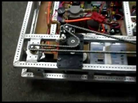


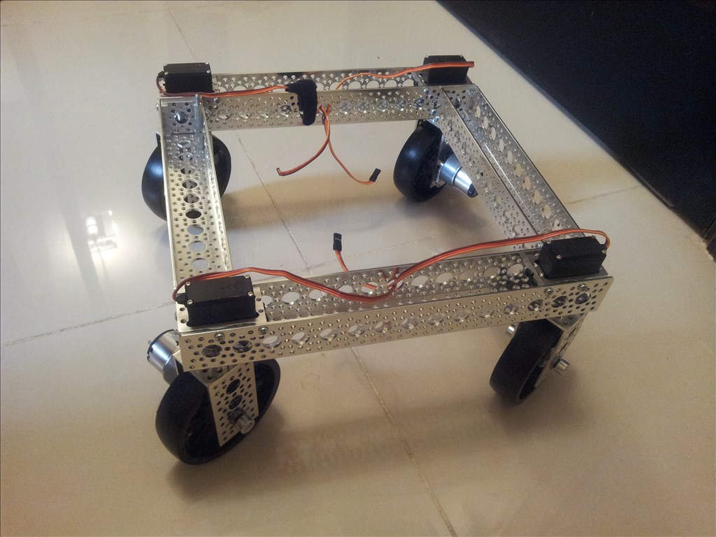


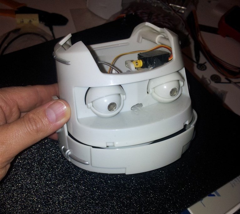
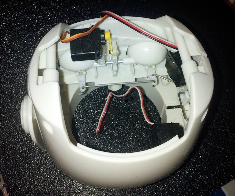


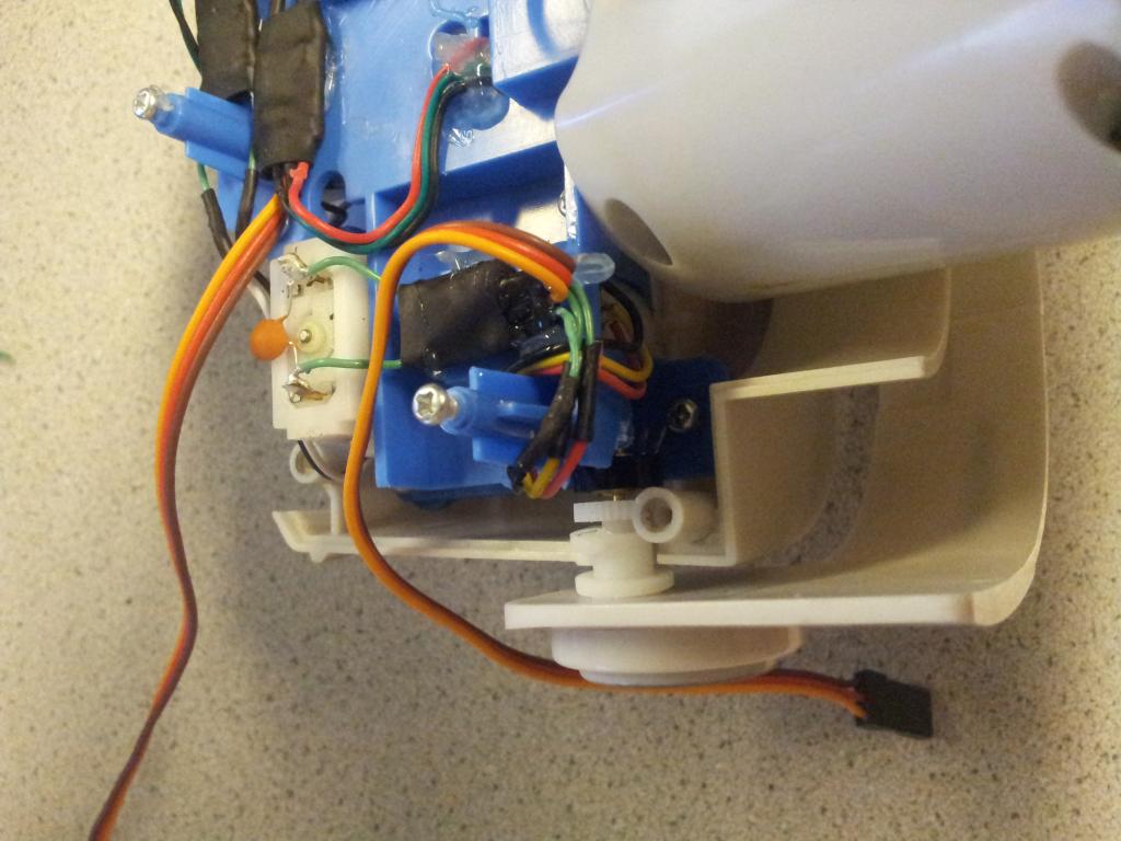

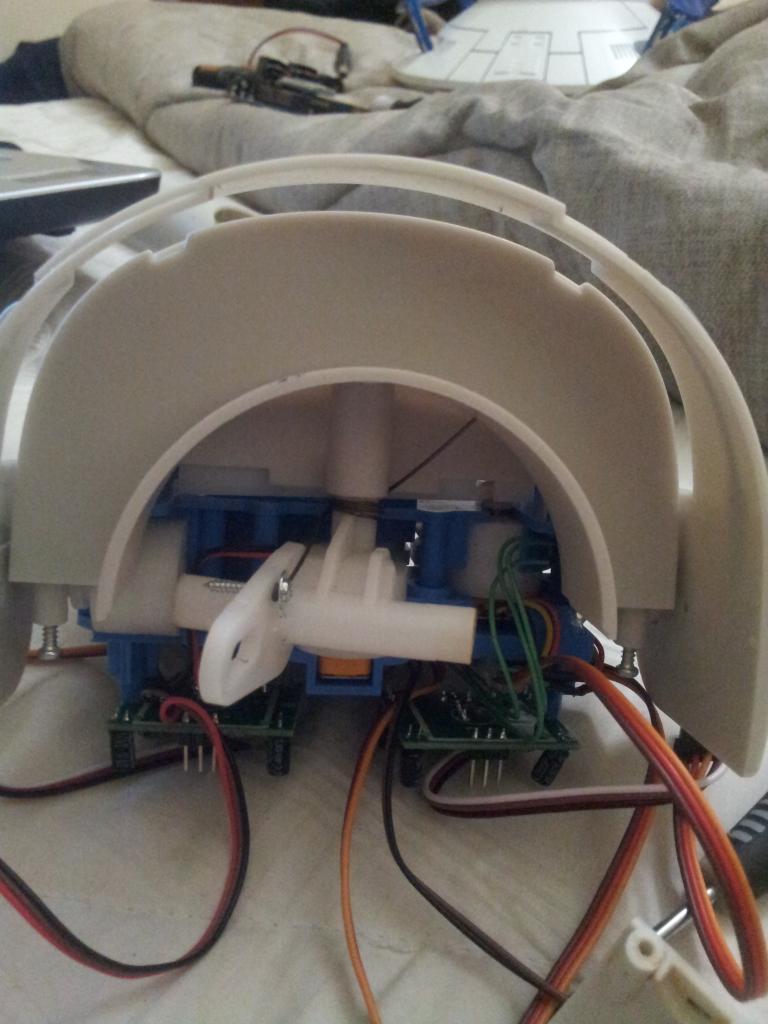

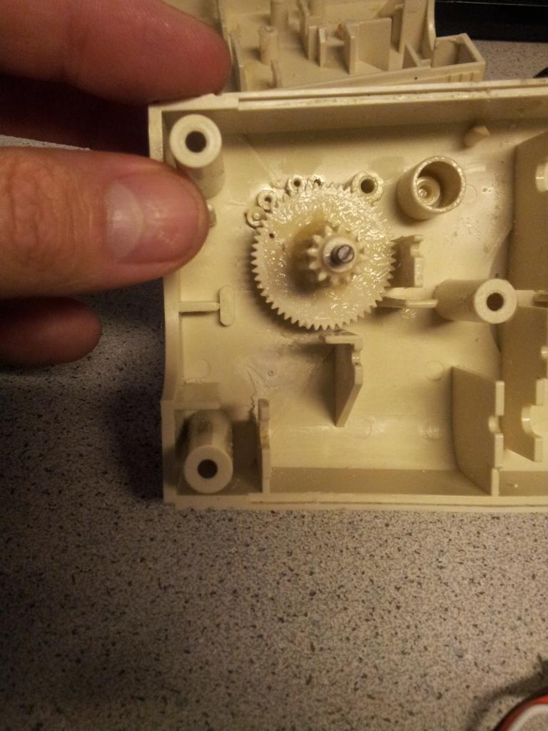


It's just a concept right now but I wanted others to see that the scale doesnt quite match. Right now its just stacked on there and neck is a little too long.
By Troy
— Last update
Discover more robots
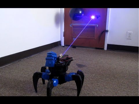
Nomad's Using Robosapien V2
Customize V2 robot with EZ-B4: left shoulder camera synced to head rotation and right-side laser for shooting balloons;...

Ezang's My Tightrope Robot Without The Squeak, Sorry For The...
Tight Rope robot without the squeak - enjoy a smooth, silent balance performance
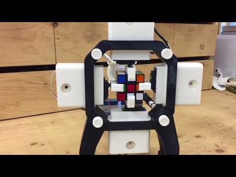
Bhouston's Rubik's Cube Solving Robot
Run a Thingiverse 3D-printed Rubik's Cube robot with EZ-Robot servos and IoTiny; plugin for cube-solving, arm/gripper...

Nice fix! Good thinking.
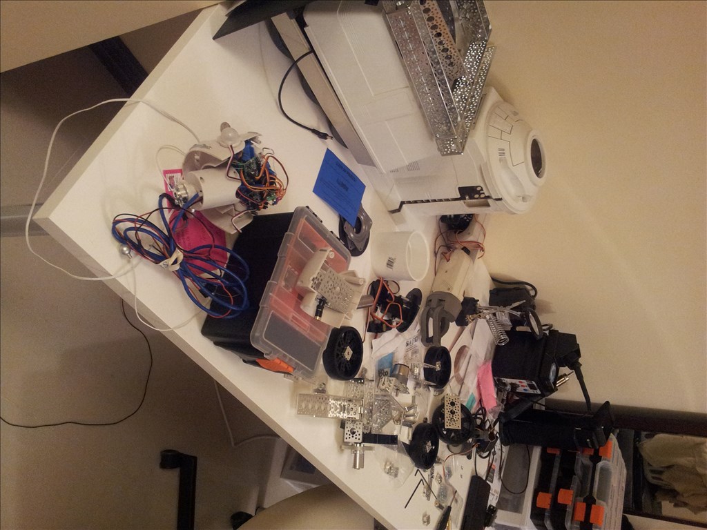
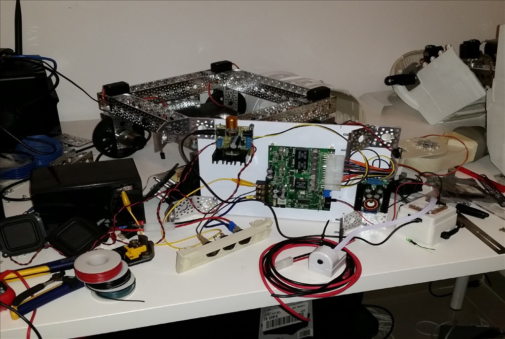
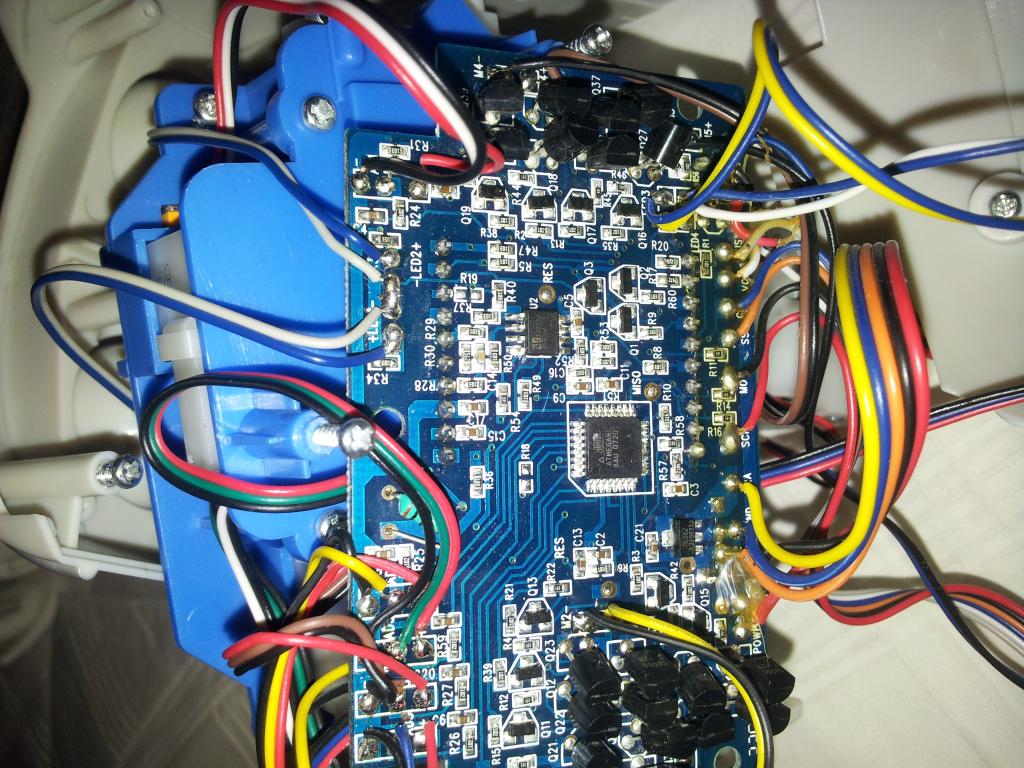
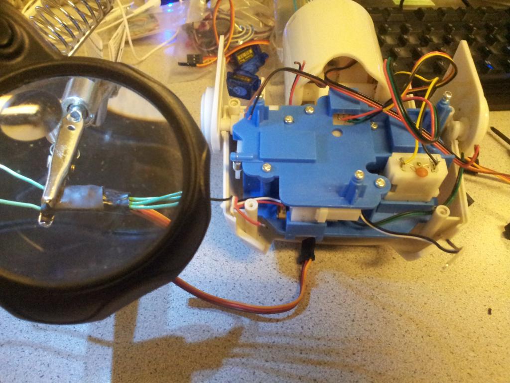
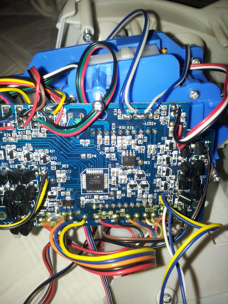
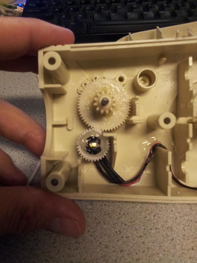
Thanks Bret. I just got lucky again. After looking at all this wiring I see I need to run a single power line and ground line up and combine the servo signals in a single multipair cable down. Maybe some CAT5 will do the trick.
becareful about using CAT5 with having power next to your signal wires i would use CAT5 for all signals with a gnd and then a sperate red and black wire twisted to remove(block) the eddy currents
Thanks for clarifying what I thought I said. But remember this is low voltage DC not AC. I'm pretty sure I won't induce a signal on the signal wires. If anything the signal wires themselves may induce on each other. I will have to test and see. IDK Im running power outside the CAT5 because it will go to the power source and not to the EZB.
yes it does a lot mostly on sensors,makes the signal unstable,thats why companies use SPG alot thats where all grounds go to a single point all i make at work is ultra high precision in-house testers,and this comes up alot and on robots i made, it does also,noise you will see a lot are on sonars or servo's that use high frequency,if using very low current wont see the problem that much ,but over 500 ma you may hopefully this will explain it for you mostly hard to tell if you have any noise in your system ,unles you have a O-SCOPE or have a tester to check the sensors,most people hook it up and thinks the reading is good ,because it shows a reading,like on sonars how do you know if you sonar measures 1 inch or 2 inches or 12 inches or 13 inches(not calibrated correctly) or reading is jumpy (unstable)
on AC its much different,called HUM,BUT there is no ac on a robot
another idea on using sensors is use 10 mfd right next to the power we on the sonar board it helps git rid of unstablity
I got confused for a second. As long as the power and ground are not inside the same cable it can't be a problem. I have seen DC currents passing through twisted pair causing inductance (little electromagnet field) which in cases of data can cause interference. Maybe just use the cat 5 for signals and grounds but.run your power wire outside the cat 5 which would prevent any inductance. Problem solved easily and still near wiring =)
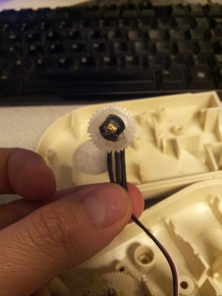
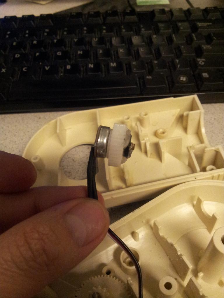
Fred, look at your servo cables. Its GND, POWER, SIGNAL. Power and signal are right next to each other. I imagine its not a big factor in the way its used in RC industry. Thanks Josh, I will probably tie a separate signal gnd in.
yes as long as the wires on the outside of CAT5 ,you wont see a problem mostly i read glickclick a litlle wrong,but at the same time i put the info up to help others too CAT5 is a shielded wire,but even with CAT5 wire some sonars might be unstable,mostly with china made,without a good scope cant see this problem,and on a robot you wont see it,and your navigation could be off,mostly i use shielded computer wire,and high current wire for my power,i still twist them you can only get you CAT5 SO close to the sensors or servo's and still some will be exposed so always twist the wires,at work i made a a twisted wire machine for prodution to twist a few or alot,for the same problem,nnoise in the system
JOSH YOU SAID that you saw dc currents pass though a twisted wire ,did you have a SCOPE,ONLY WAY TO SEE THIS, one reason twisted wire is red is crossed over to black wire to block the eddy current,and same with blck wire,so it blocks each other out and also causing inductance another item used is where the wire connects to the board you place a 10 mfd cap and ferrite beads are used sometimes too