


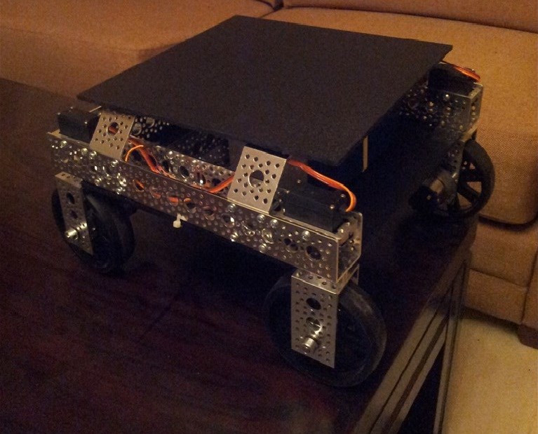


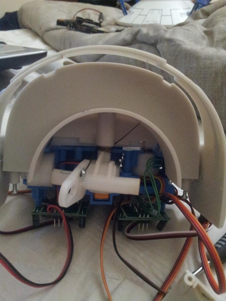


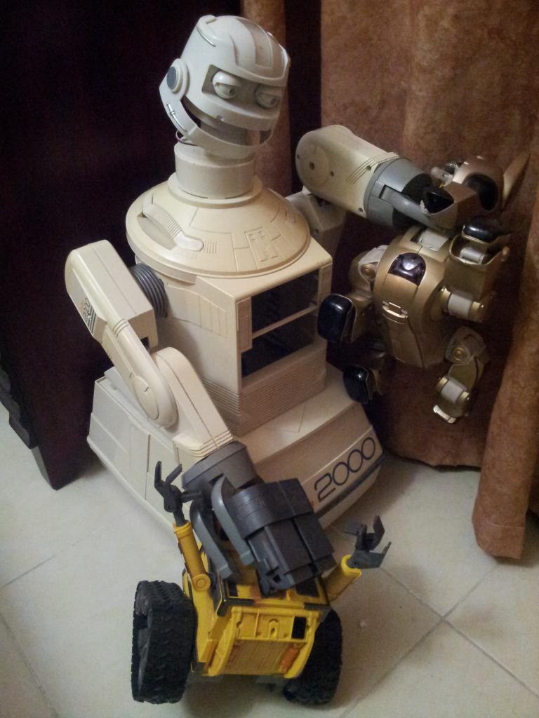
It's just a concept right now but I wanted others to see that the scale doesnt quite match. Right now its just stacked on there and neck is a little too long.
By Troy
— Last update
Discover more robots
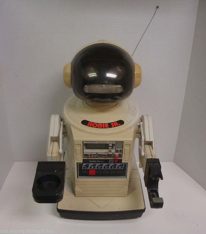
JT's Jts Robie Sr.
Restoring a Robie SR for EZ-B-ification: raising height ~6 in, adding a turning/tilting neck, new paint, learning...
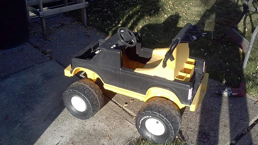
J's My New Toy I'm Building
Power Wheels converted with a paintball turret on bike forks, actuator for vertical control, drive speed controller and...
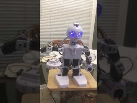
Ezang's Robot With Audio Voice Command And Audio Response
EzAng robot with audio voice command and audio response enables voice-controlled operation and spoken feedback

I think it looks good.
Mel
Thanks. It looks a little smaller than in this photo for some reason. Anyways I think it will add to his comical nature. lol
I really like it.
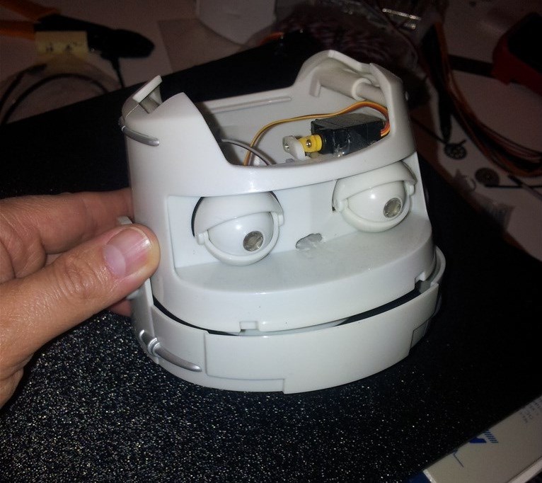
When I saw there was a headless Omni2000 on eBay I decided to go for it. I thought it would go for cheap and it did. About $65.
looks very good,i kinda had a idea like it for mine too
@robotmaker They seem to be harder to find on eBay than Omni2000s. :/ I had an email alert for when it finally showed up. Also robotmaker I may be hitting you up later on recommendations for batteries and power charging system with an embedded PC board. It wont be as high end as Jstarnes though.
glad you where able to get him
@Glickclik - HEY! I was bidding on that headless Omnibot 2000 too! Oh, well, all's fair in love & eBay... I'm just glad someone here won it. It was perfect to be EZ-B-ified.
btw, what is his head from again? What's it called?