
-636348381130562972.jpg)
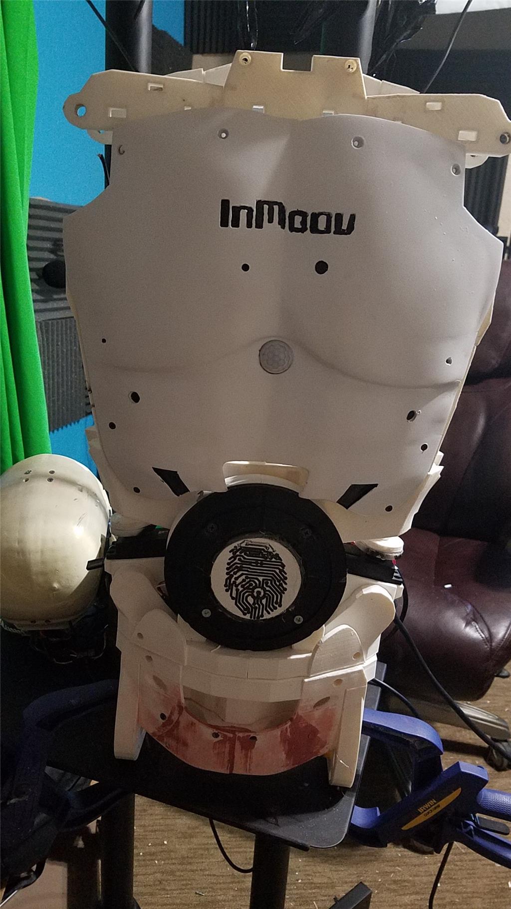
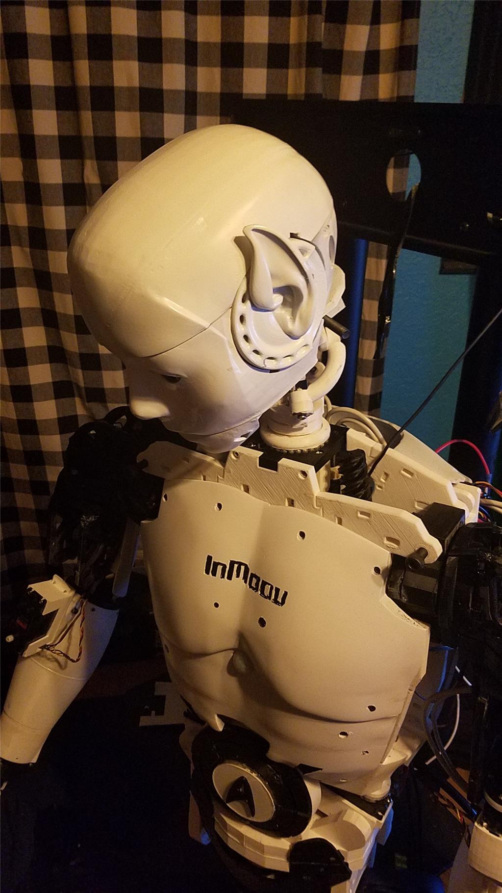
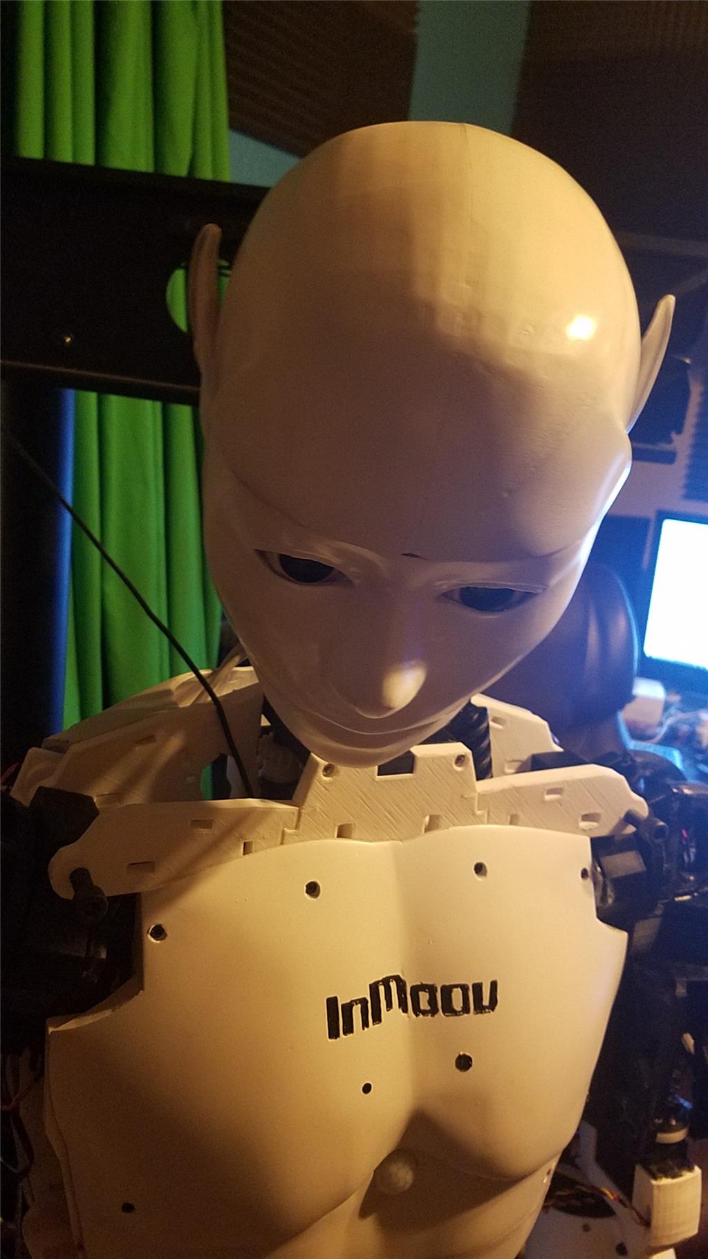


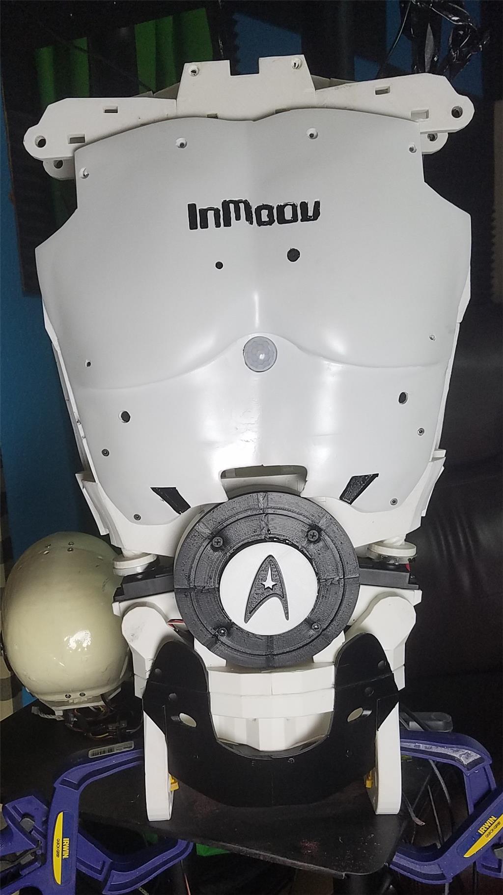


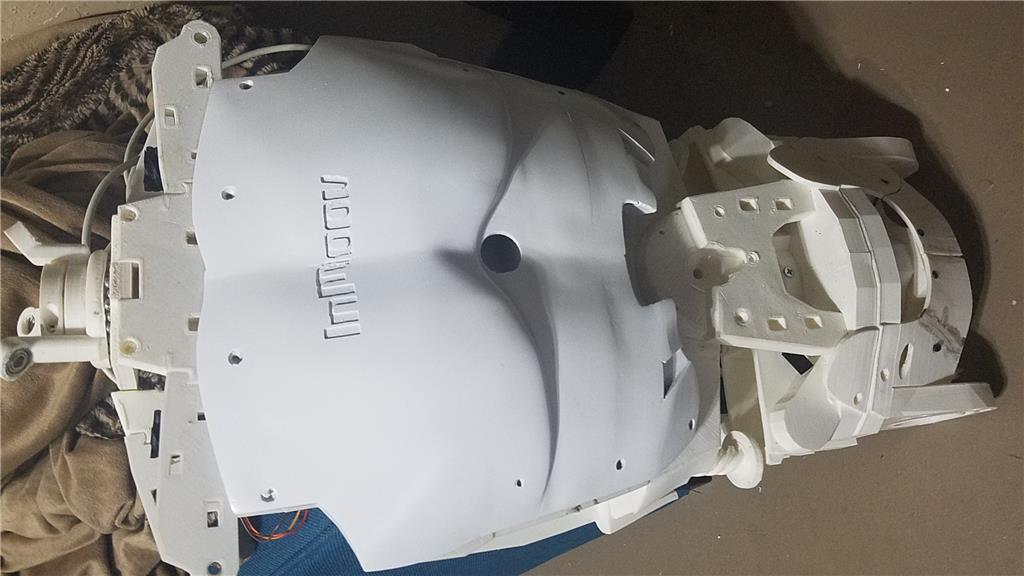
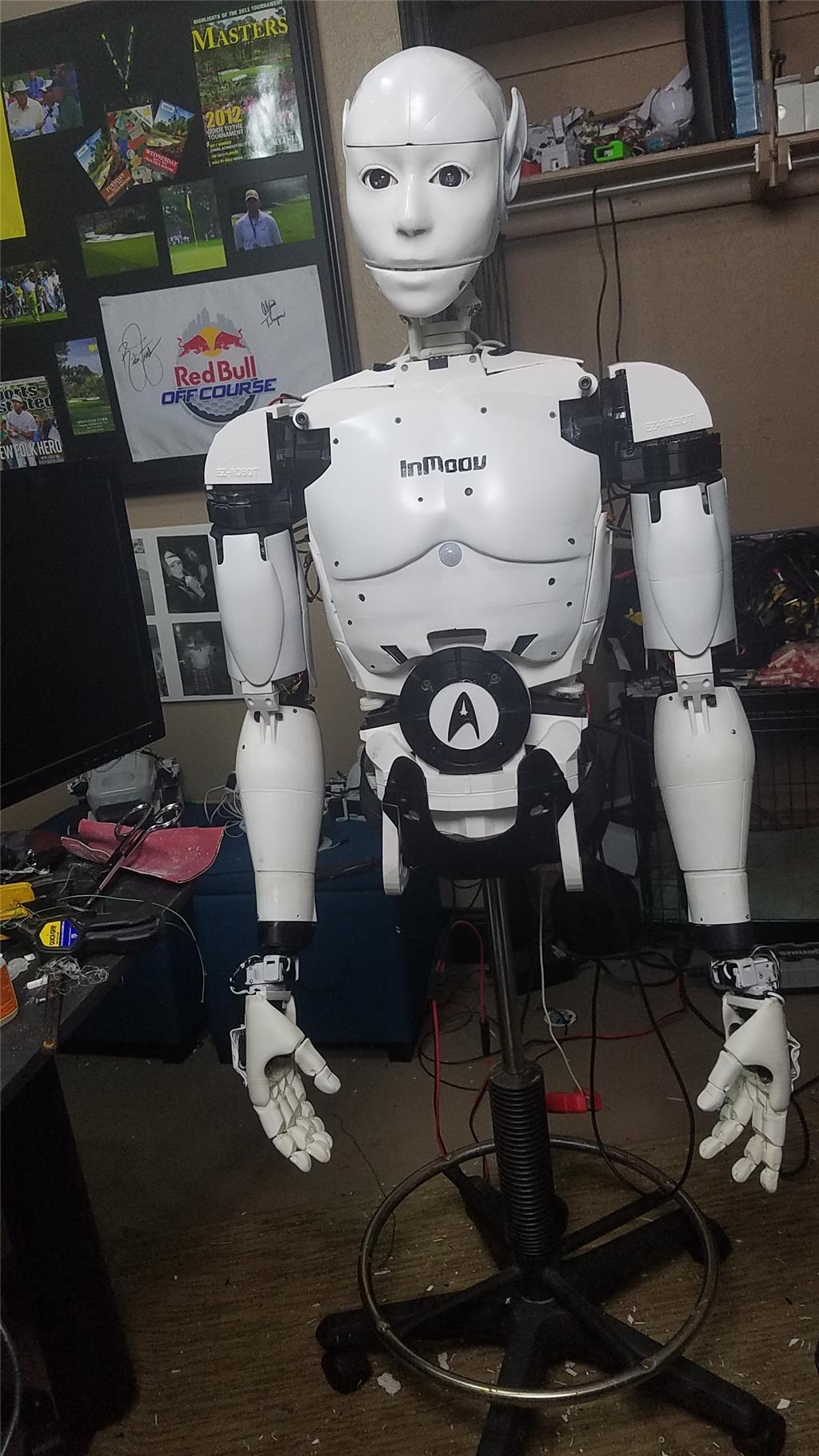
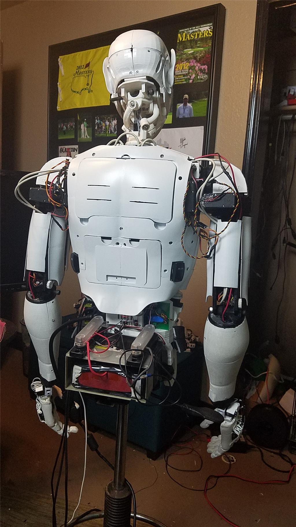
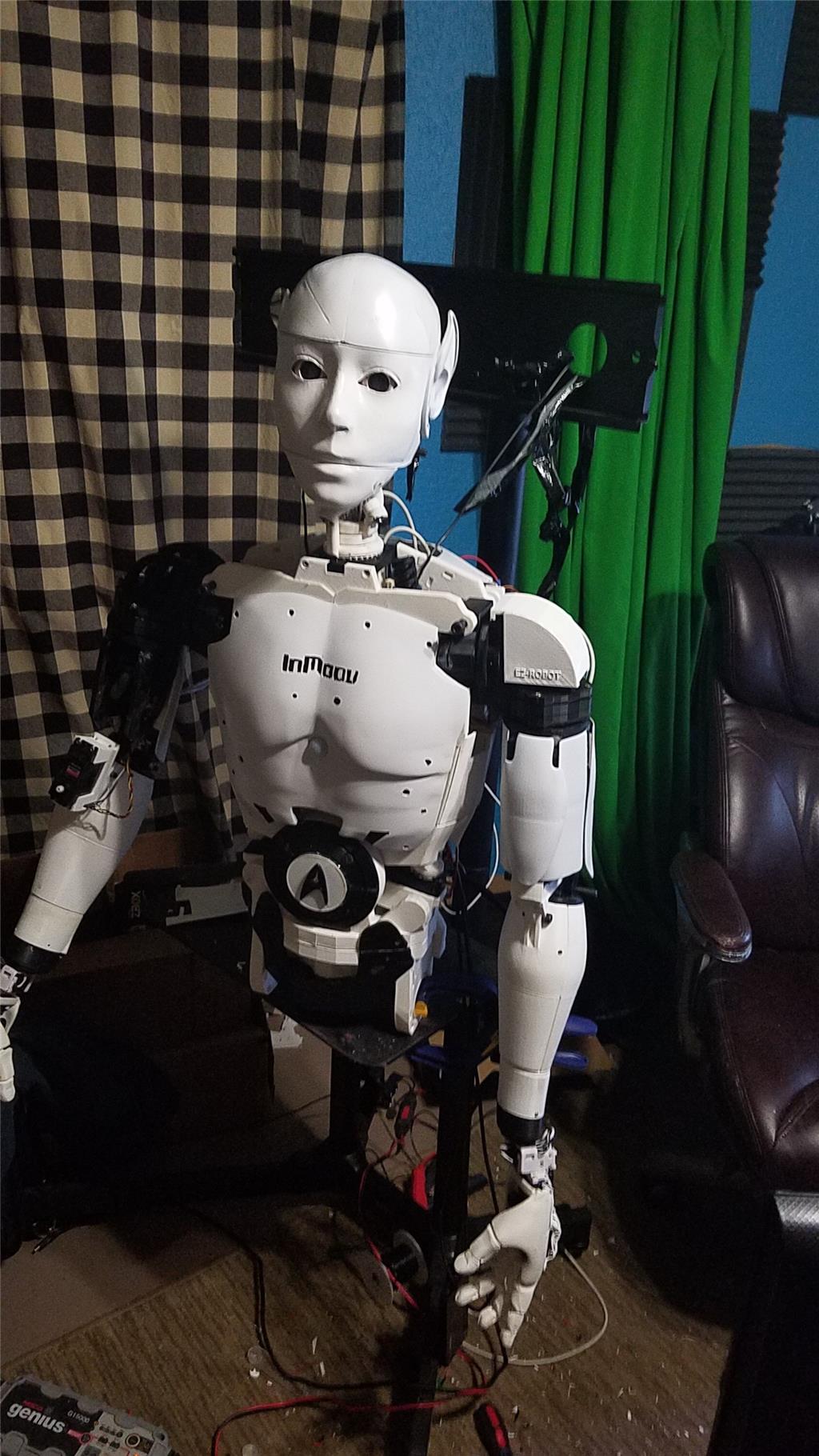
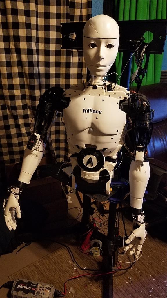
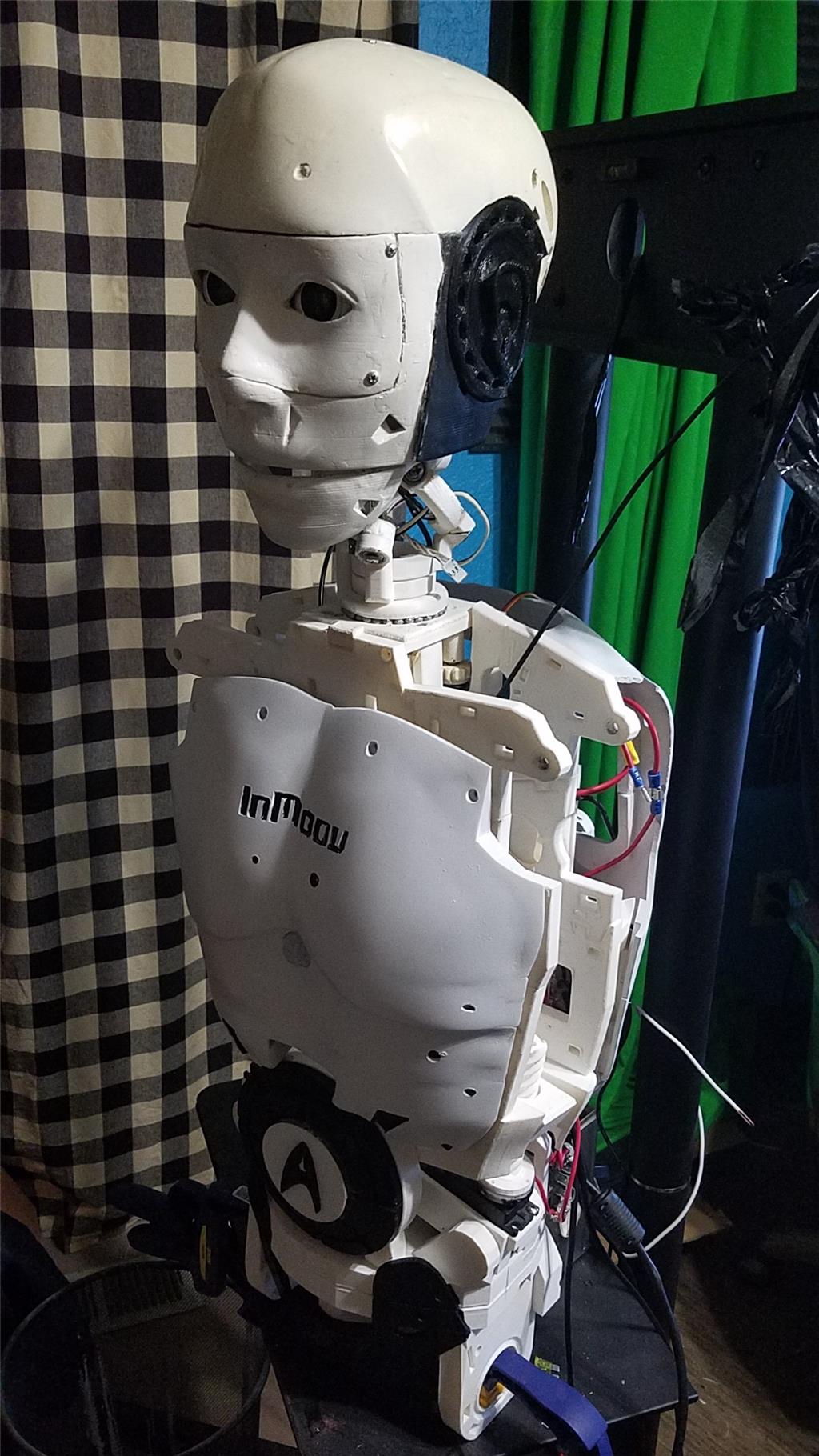
I have decided to start my InMoov project. I think I will call him Spock out of respect to Leonard Nimoy who passed away on the day that I started this project.
I am editing this post so as not to confuse people with the current configuration. I continue to update this post with the latest photos. If you are reading this for the first time, don't be confused. There have been a lot of changes to the InMoov over the past couple of years including starting over.
https://synthiam.com/Community/Questions/7398&page=21 Post 203 starts the rebuild of the InMoov.
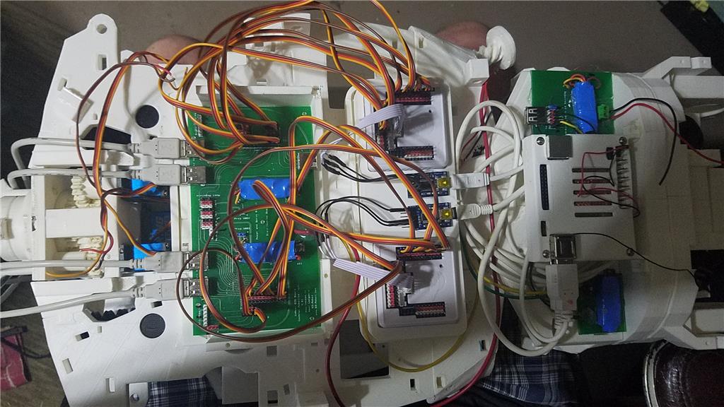
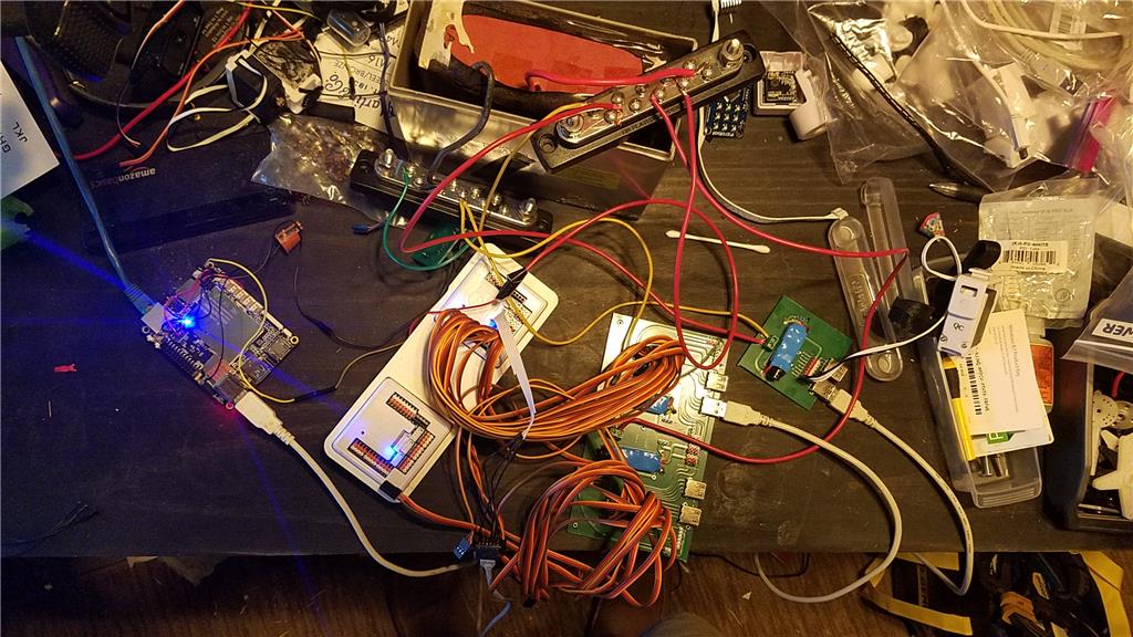
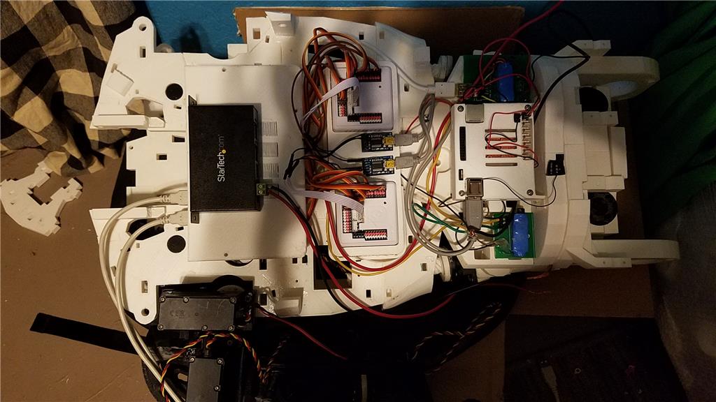
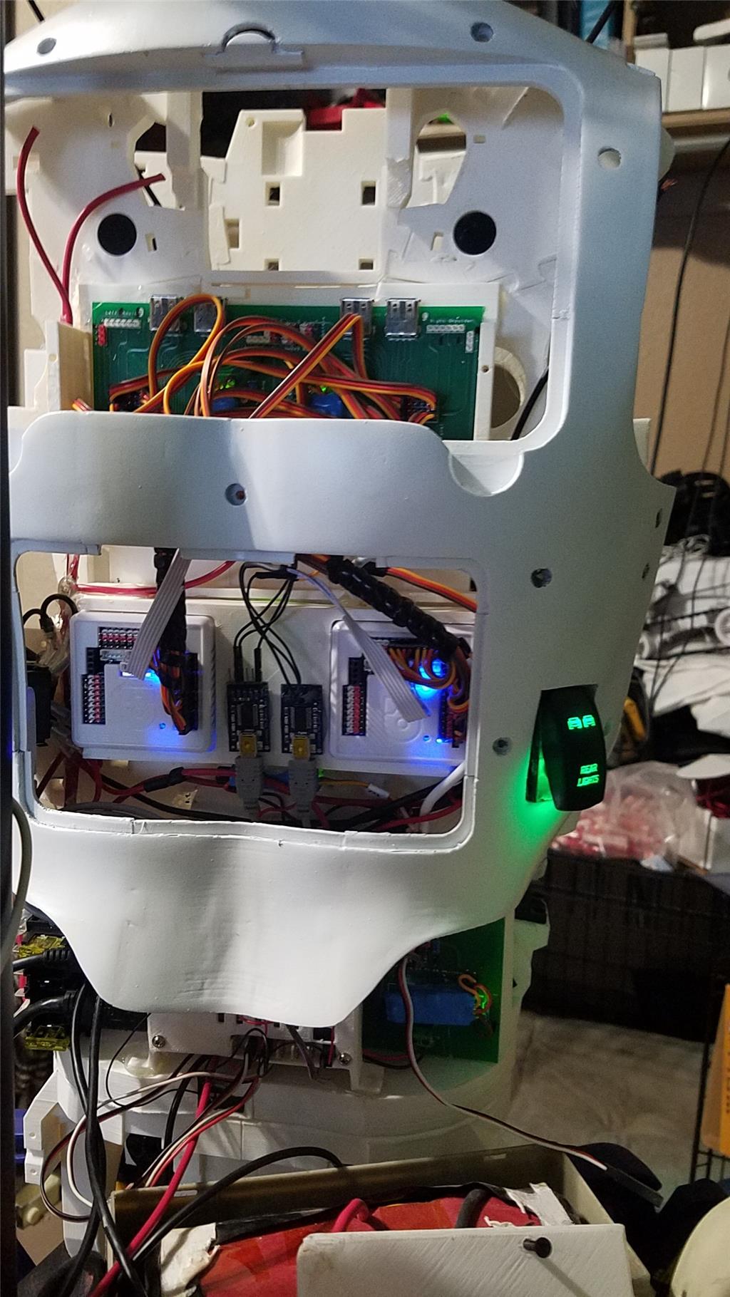
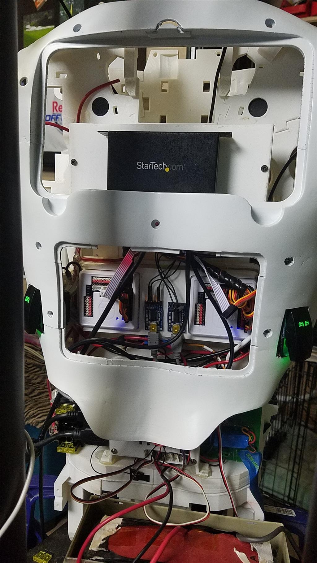
I have decided to use an onboard computer. I chose the Latte Panda due to it having an onboard arduino Leonardo and also because it uses little power.
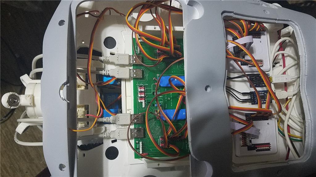
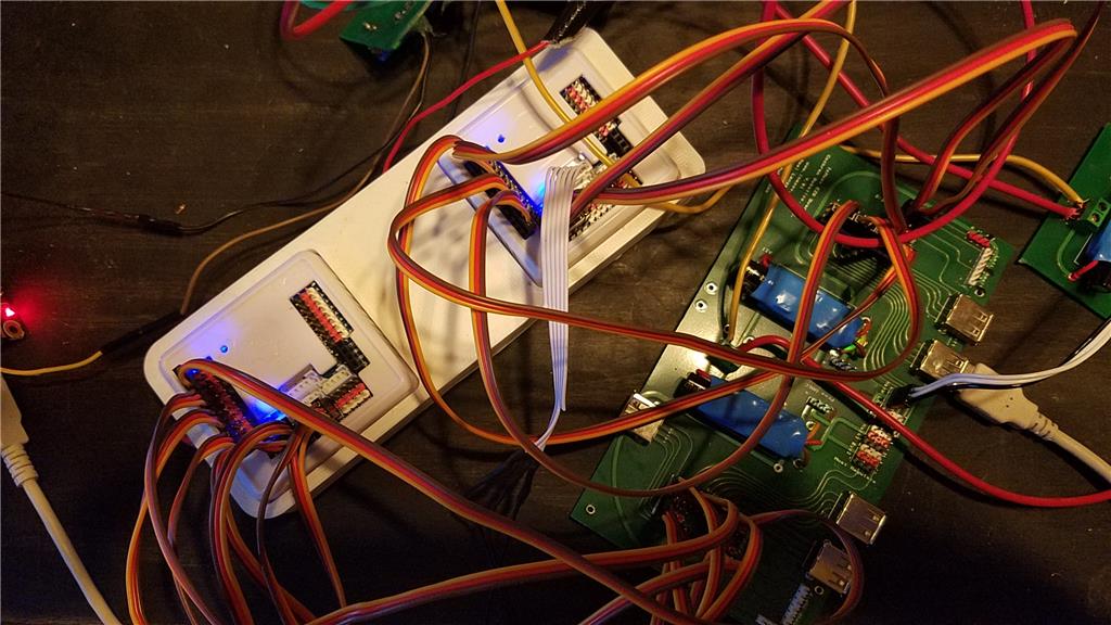
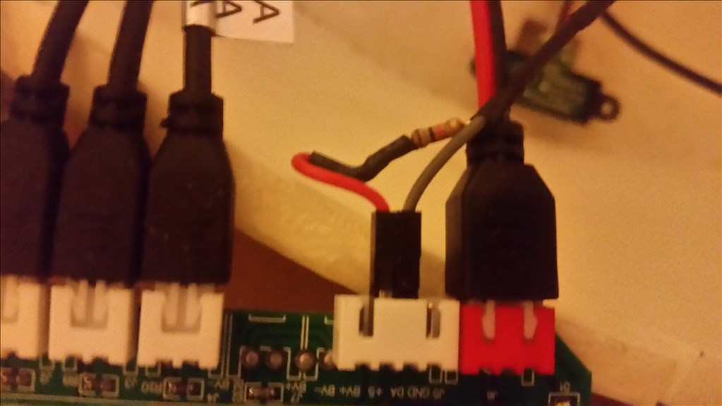
I used 2 EZ-B controllers connected via the camera port to Adafruit FTDI friend boards. This allows the Latte Panda to have a non-wifi dependent connection to the EZ-B's. I use a powered USB hub connected to the USB3 port on the Latte Panda to attach other items.
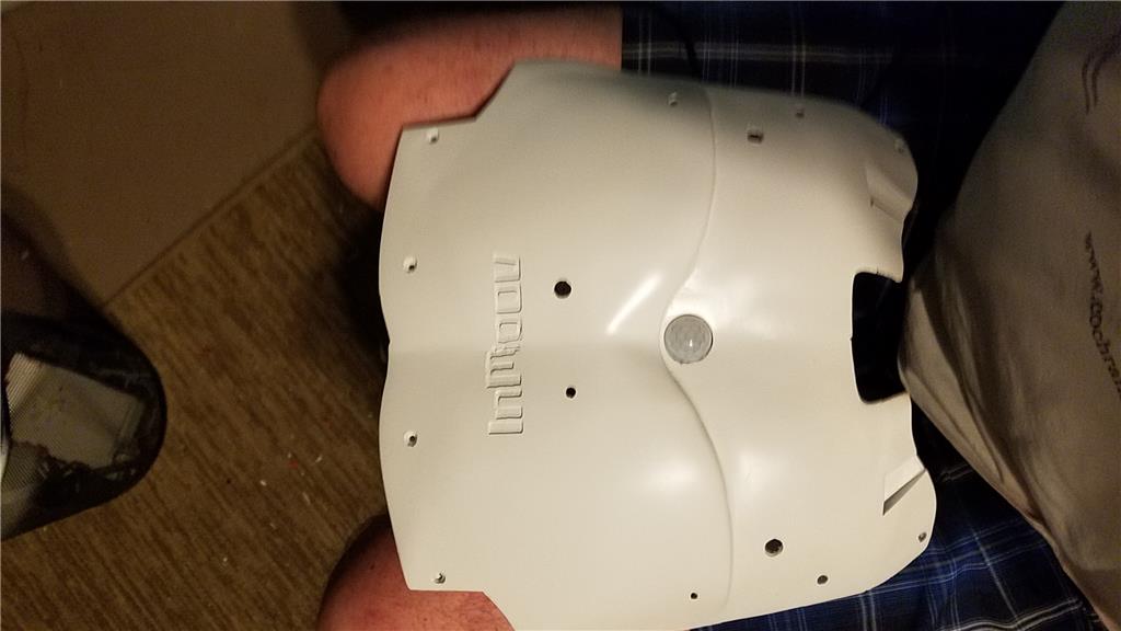
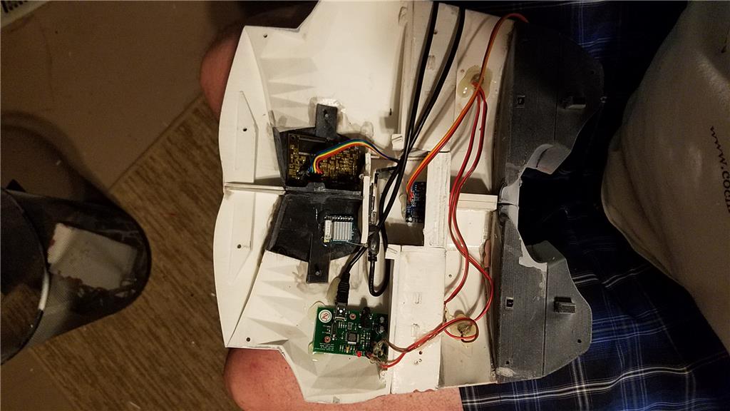
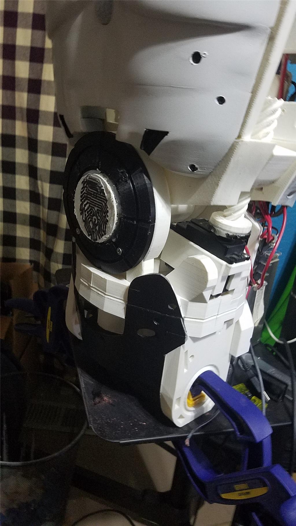
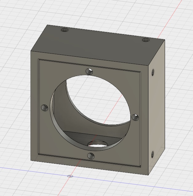
The Omron HVC-P is used to identify people, emotions, human bodies, hands, age and gender. It is attached to the Latte Panda via an FTDI friend which is then connected to the powered USB hub. It is mounted in the chest of the InMoov. I also use a 3 element microphone which is a MXL AC-404 microphone. It is disassembled and the board and microphone elements are mounted in the chest of the InMoov. This mic board is connected to the Latte Panda via a usb cable which is attached to the powered USB hub. There is a USB camera in the eye of the InMoov which is connected to the Latte Panda via the powered USB hub.
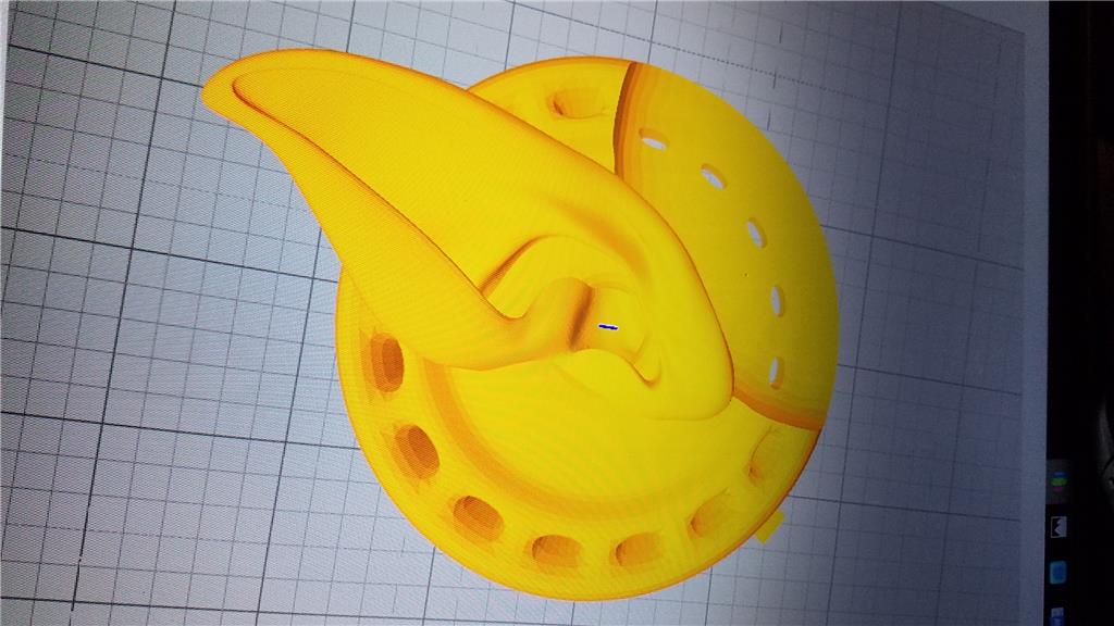
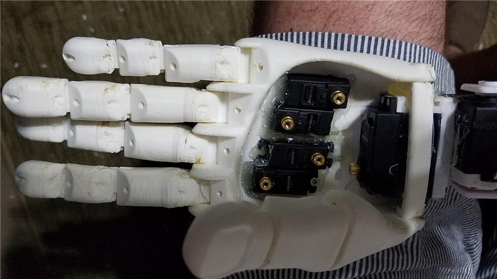
I chose to use the Flexy hand with the InMoov. The design is far more rugged than the original hand and works very well. There are 4 EZ-Robot Micro Servos in the palm of each hand which controls the main fingers. The thumb is controlled by an EZ-Robot HD servo. The wrist waves and uses an EZ-Robot HD servo to do this motion. I use the standard Rotational wrist.
I have castle BEC's for power in the following locations set to the following voltages. Forearm's - 6.2 V - Controls fingers, wrist and elbows Custom power distribution board (2) set to 6.2 V controlling head, neck and Shoulder servos. EZ-B's - set to 6.1 V - it is mounted in the controller mounting plate and connects to the EZ-B fused power boards from a power base. Latte Panda - Set to 5.1 V and is mounted to the EZ-B controller mounting plate. Waist - set to 6.2 V and is mounted in the lower right side of the back. This provides power to the lean and pivot waist motors..
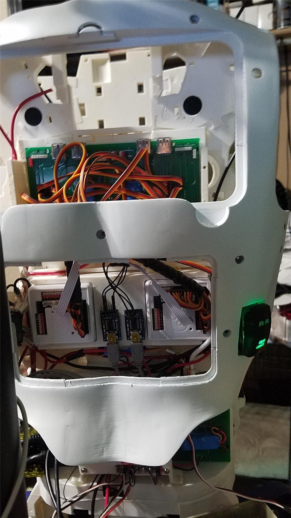
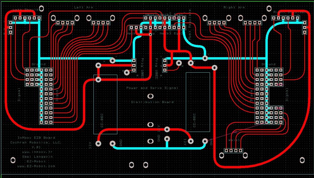
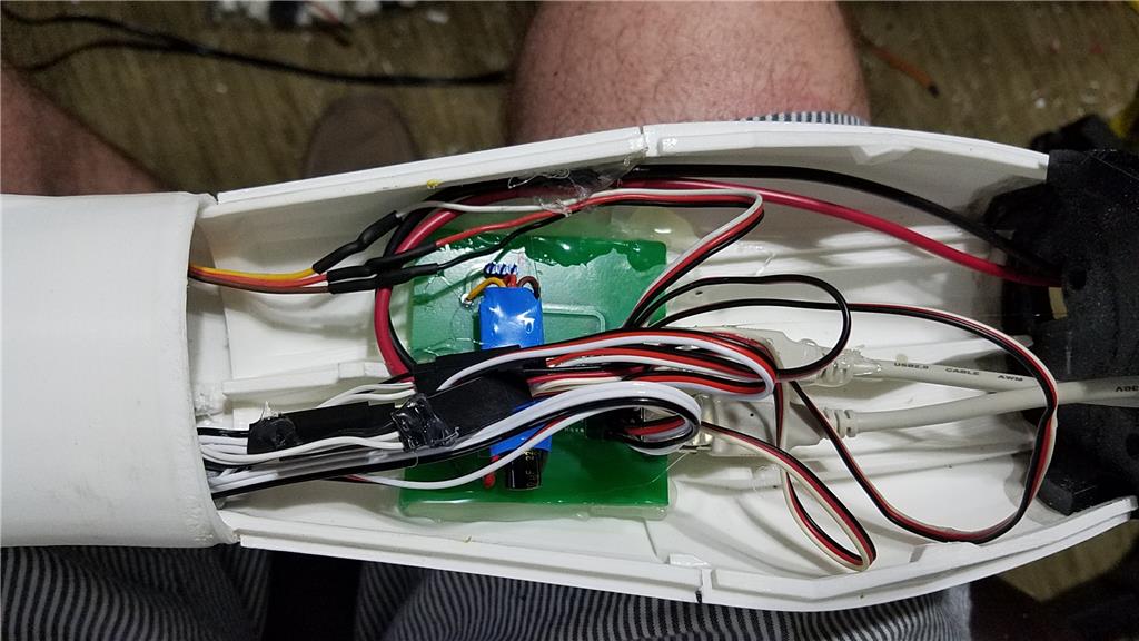
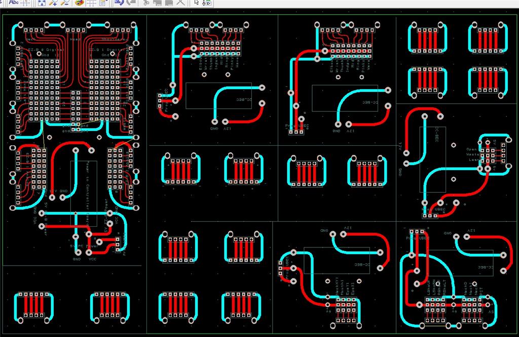
There are some custom power and signal distribution boards. These are in the forearms, lower back and in the upper back. The upper back or main board connects to these distribution points via USB cables to provide signal to the other boards for servos. The main board also has servo connector pins that are for the neck, head and shoulders. This allows the power to be distributed between multiple BEC's and also allows the servo signal cables to be shorter and more protected via the USB cables.
For power I use a LiFePo4 battery that is rated at 30 amps. It has the balanced charging circuit built into the battery and also has a low voltage shutoff built into the battery. This protects the battery and allows the battery to be charged with standard car chargers.
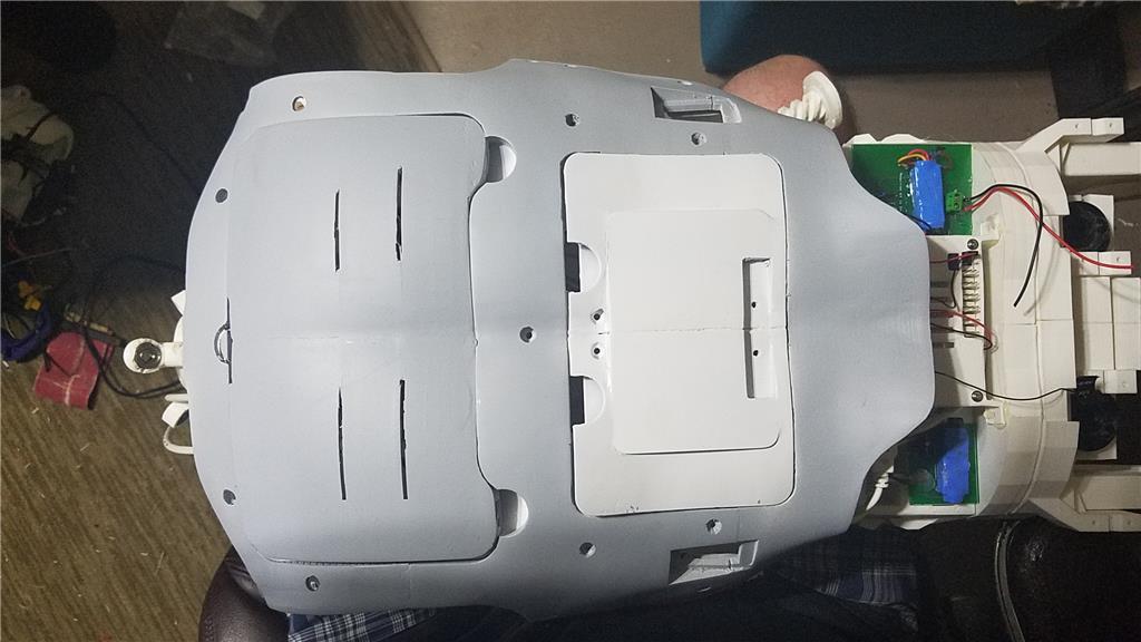
I put switches on the back on the InMoov which are rated at 20 amps at 12 volts. These are rocker switches that allow the user to pretty much slap the switch to turn it off. There are two of these switches. The servos for the elbows and fingers are on one switch. The latte panda, neck, shoulders, EZ-B's, waist motors and some lighting is on the other switch.
I also added a fuse block. This allows 20 amp fuses to be put in line to help protect things. The switches above drive the fuses for each of of the motors listed in that section.
-636348716348649435.jpg)

Discover more robots
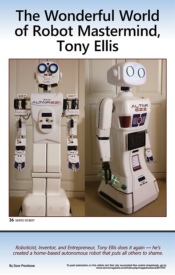
Toymaker's Altair Robots In Servo Magazine
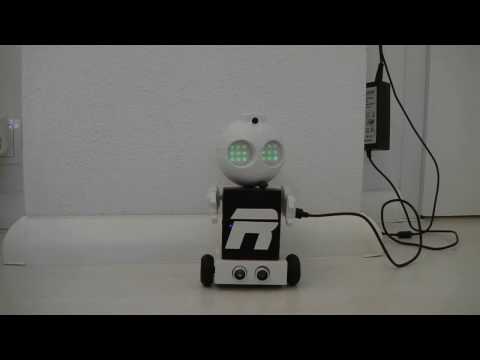
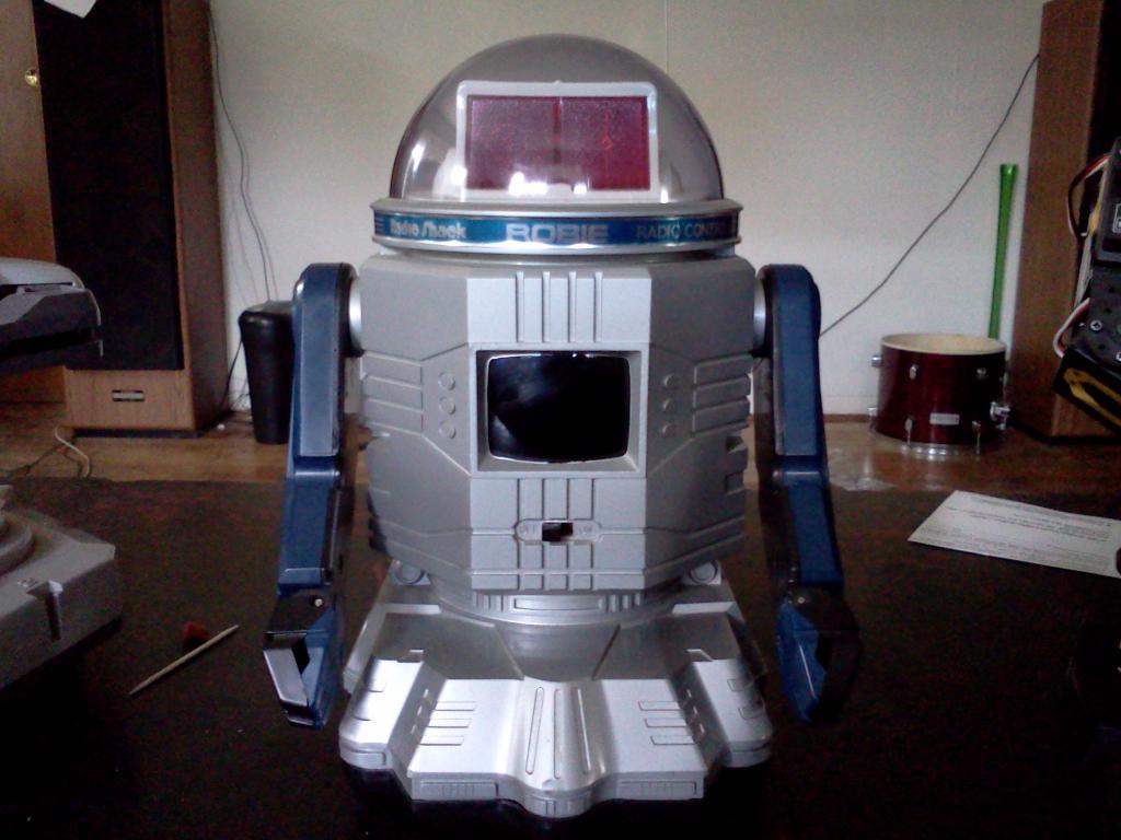
Lizpoir's Video From My Omnibot 2000 An From My 3D-Printing...

Yea, I can find them for anywhere from about $5 each to about $15 each. That seems like a huge range in price to me and there has to be a reason that some are $5 and some are $15. I know some are knockoffs but as with anything else, it is hard to know if this is an issue or not. Arduino is open source so knockoffs aren't such a bad thing unless they don't work with something.
Doing a lot of research. You know, robotics takes you in directions by noon you never conceived of at 8:00 AM.
If you can't find enough room to fit the EZB into the bicep, here is a nice place to sit the EZB Still part of the arm with no negative weight effect, Acessible and hiden from the front .
Okay, order has been placed for a mini, the FTDI board and a neopixel ring. I will see what I can do with it before diving into adding one for each EZ-B.
If you buy the Arduino mini you will need this in order to program them... USB to serial adapter I believe the micro has it built in...
EDIT Never mind I see you already knew that...
That is the same as this, right?
FTDI board
@Aerius, Great idea. Thank you!
@Richard R, Thank you anyway! I do appreciate it.
@David...Yep, I am pretty sure they are the same thing so you're good...
I have been updating the original post with parts as I receive them. It isnt a complete list yet but it is growing. I will keep updating that first post as I get new items.
Today I should receive all of the 3D printed parts (Thanks @Mernie). The package is 22 lbs for all of the parts. There are some extra parts being shipped but I would estimate that the 3D printed pieces of an inmoov will weigh about 18 lbs.
Example LiFePo4 battery - These are listed at 12V but I suspect they are actually more like 15 to 12 volts. I guess that they could have a regulator built into them, but I haven't done enough research on these yet to know.
There is a 12V 100Ah LiFePO4 battery also that I am looking at.Another battery example
I am considering changing out the batteries for lipo 12V(?) 35AH batteries. These batteries will be more expensive but will weigh about 1/5 the weight of the SLA batteries and will last about 4 times longer. This should allow me to reduce the number of batteries that I need down to 2 lipo's instead of 6 SLA batteries. This takes the weight down by about 100 lbs for the robot. By doing this, I should be able to use 12V motors instead of the 24V motors for movement of the robot. This in turn reduces more weight. The frame can then be reduced in strength which reduces more weight. All of this should allow the batteries to last longer with far fewer batteries and provide more power to other components. An additional benefit to the lipos is that they can deliver far more amps at any given time. This should prevent any brown out situations. If I went with the 100Ah battery above, the cost would be pretty much a wash as far as SLA battery cost vs one 100Ah LiFePo4 battery.
These batteries cost about 5 times what the SLA batteries cost, but if I am purchasing 1/3 the number of batteries, and the cost of the motors for moving the robot around becomes 1/8 the cost of the monster motors that I was going to have to use, and the materials to build the base cost much less, I think I actually save money by using the far more expensive batteries. I will have to regulate the 15ish volts down to 12 volts, but 25A 6V and 10 amp 5V regulators that I currently have should handle that without any issue. I will need to use a couple more (for 15ish volts to 12 volt for the PC and the motors).
I have also added a couple of 5 V regulators. The two 6V regulators will power the servos and the EZ-B V4's. The 5V regulators are 10A each and will power the other things like scary terry board, arduinos, neopixels and whatever else I need to limit to 5 V.
The plan is to wire the robot so that there are 5 distinct zones that only have power running to that zone. These 2 wires will have a disconnect at the start of each zone. This will allow there to be only two wires running to each zone (ground and voltage). Each zone will have a V4 that will operate only that zone. This should allow all of the wiring for each zone to be nice and tight. The arms use HDMI breakout boards to connect the V4 (which will be in the shoulder) to the lower arm with a majority of the servos. This will allow only one cable with 20 pins to pass through the elbow. I am not yet sure if I will also need to pass power wires through the elbow to the lower part of the arm or if I will be able to pass this through the HDMI cable. This layout should allow short jumper cables to be used from the V4 to the HDMI breakout board. Other signal wires would also be limited in length due to the location of the V4. Shorter wires are a good thing and keeping the wires out of rotating joints should also be a good thing.
I might also dye some of the parts. I think I am getting all white parts which is great, but I want to add some color to some of the parts. I could either paint or dye them. I will test dying on some parts that either won't be seen or won't be used. I will post pictures of the dyed parts. I have done this with nylon parts before with great success but have never tried it with PLA. I guess I could try it first with one of the EZB power bases that I wont be using to see how it looks.