Inmoov - D.cochran Style

CochranRobotics

USA

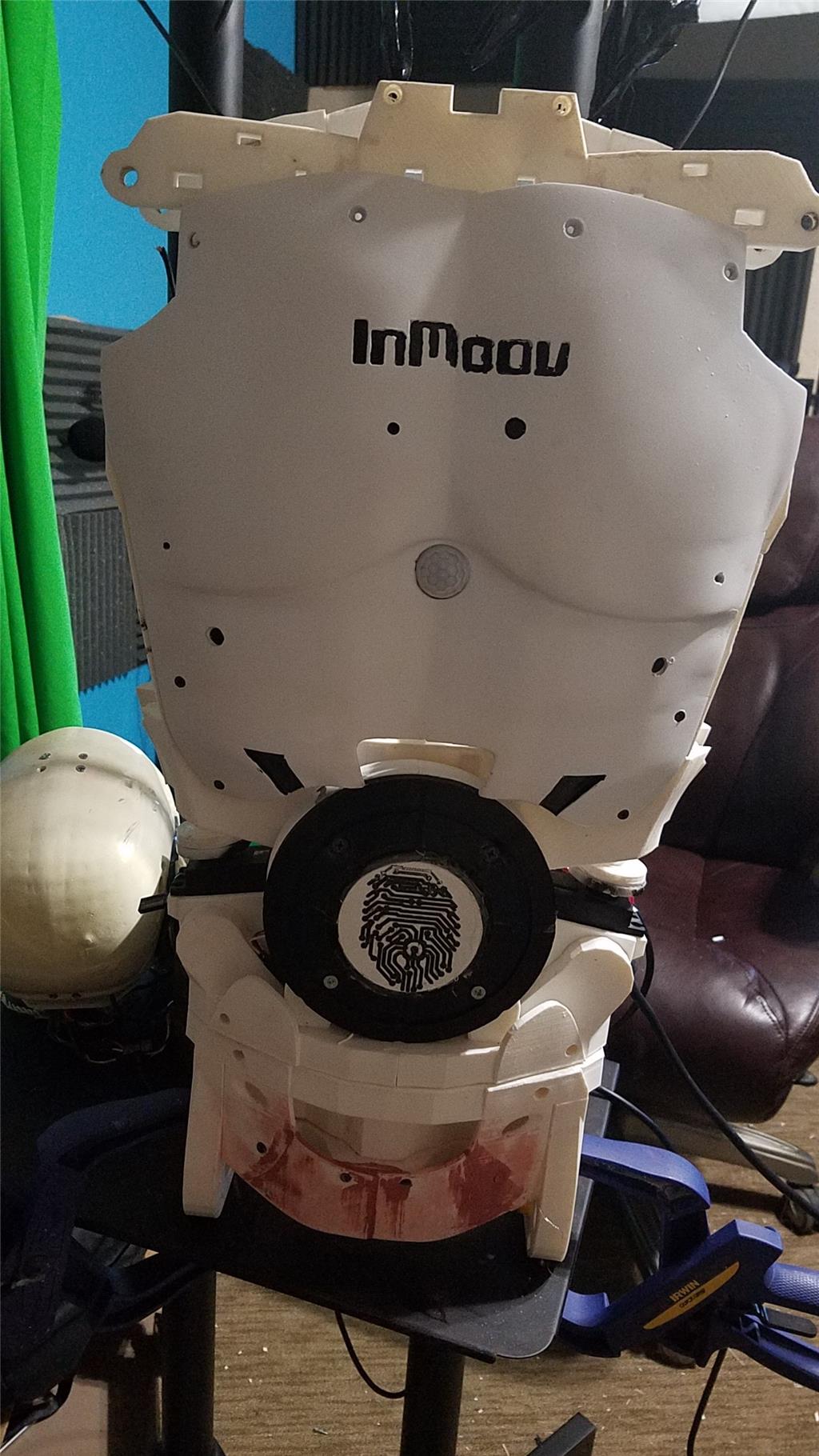
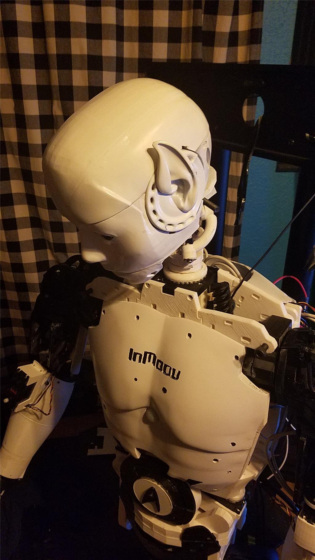
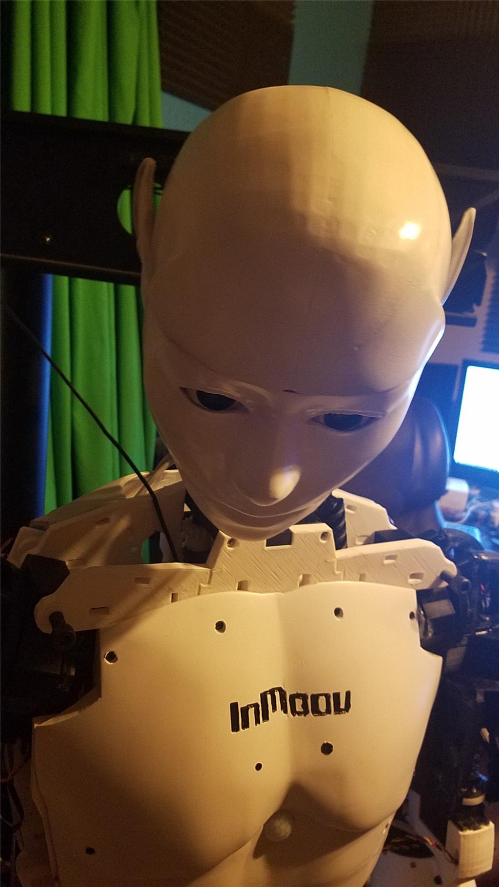
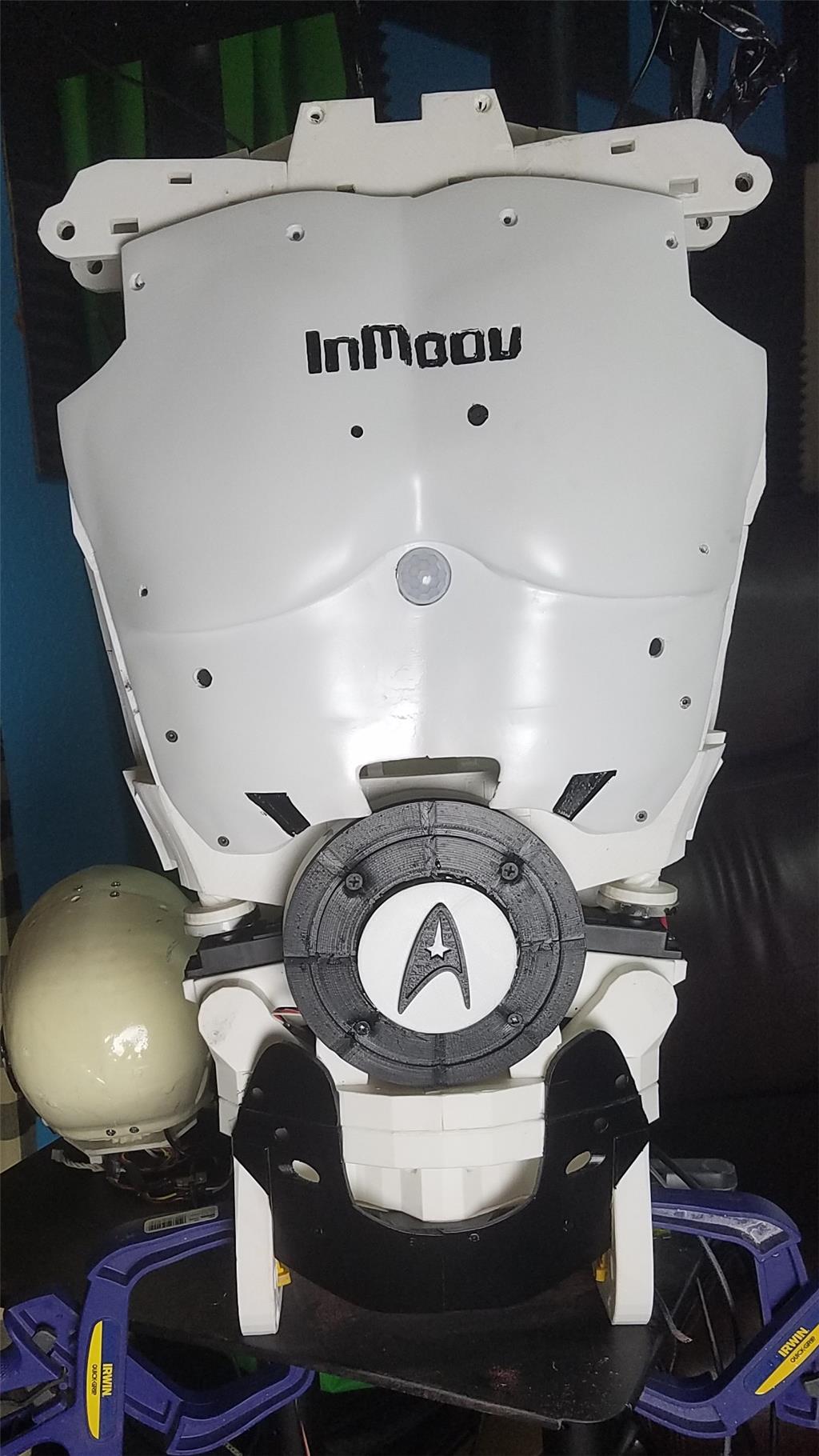
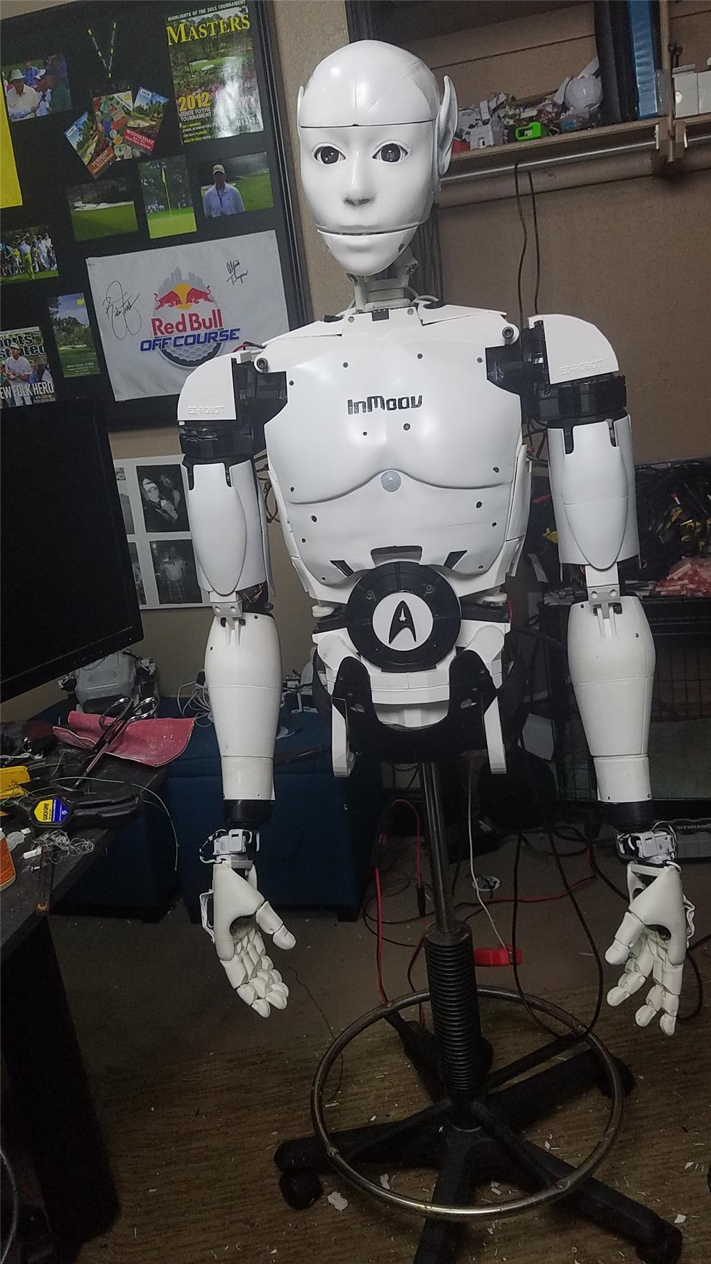
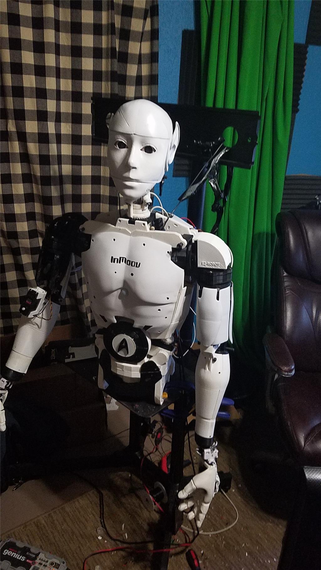
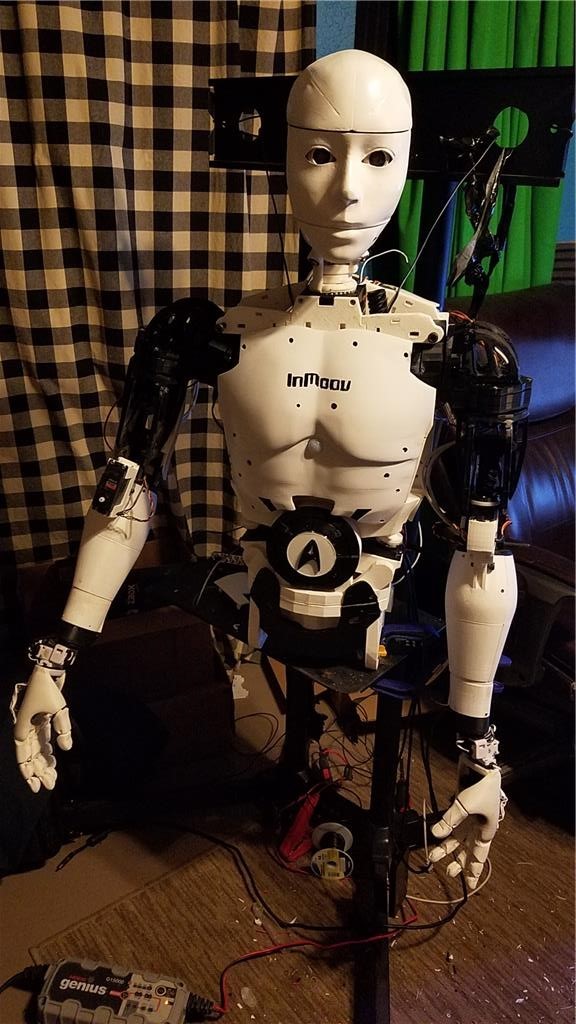
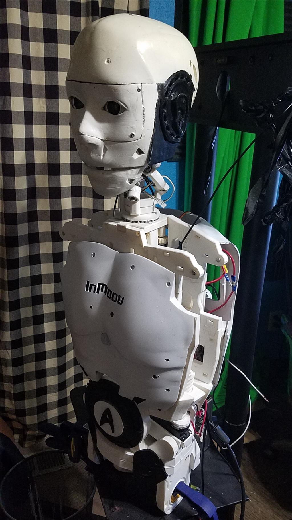
I have decided to start my InMoov project. I think I will call him Spock out of respect to Leonard Nimoy who passed away on the day that I started this project.

I am editing this post so as not to confuse people with the current configuration. I continue to update this post with the latest photos. If you are reading this for the first time, don't be confused. There have been a lot of changes to the InMoov over the past couple of years including starting over.

https://synthiam.com/Community/Questions/7398&page=21 Post 203 starts the rebuild of the InMoov.

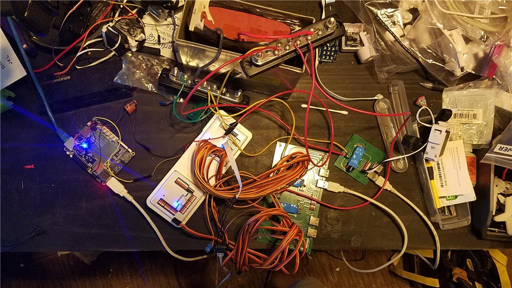
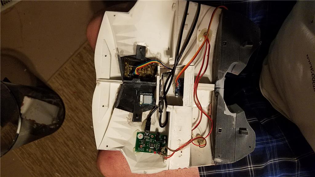
I have decided to use an onboard computer. I chose the Latte Panda due to it having an onboard arduino Leonardo and also because it uses little power.

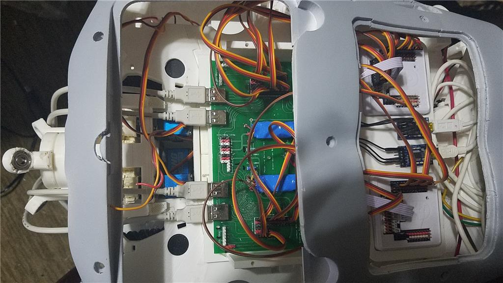
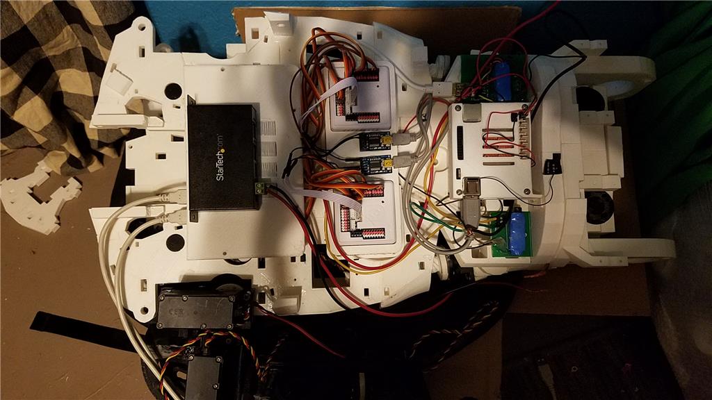
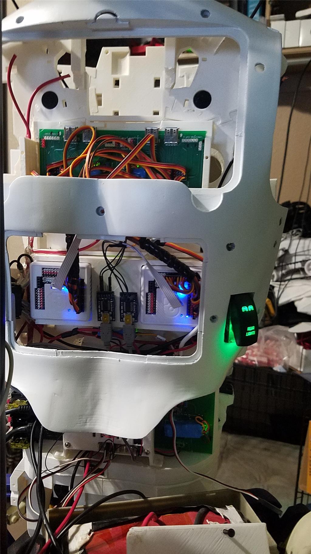
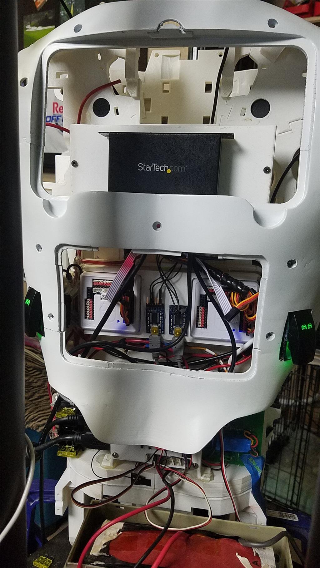
I used 2 EZ-B controllers connected via the camera port to Adafruit FTDI friend boards. This allows the Latte Panda to have a non-wifi dependent connection to the EZ-B's. I use a powered USB hub connected to the USB3 port on the Latte Panda to attach other items.

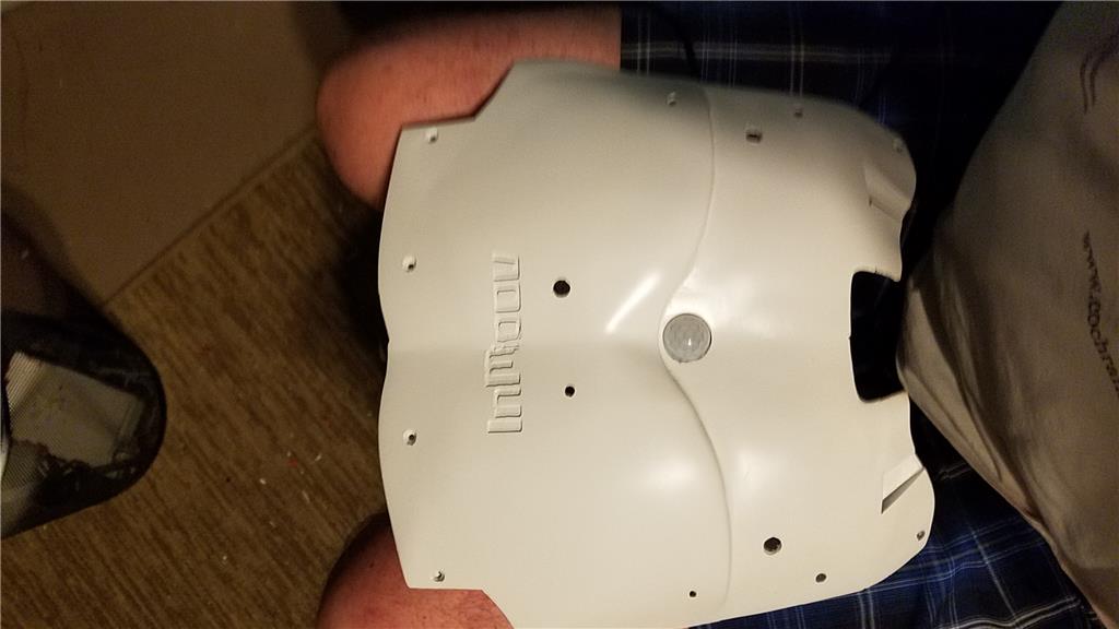
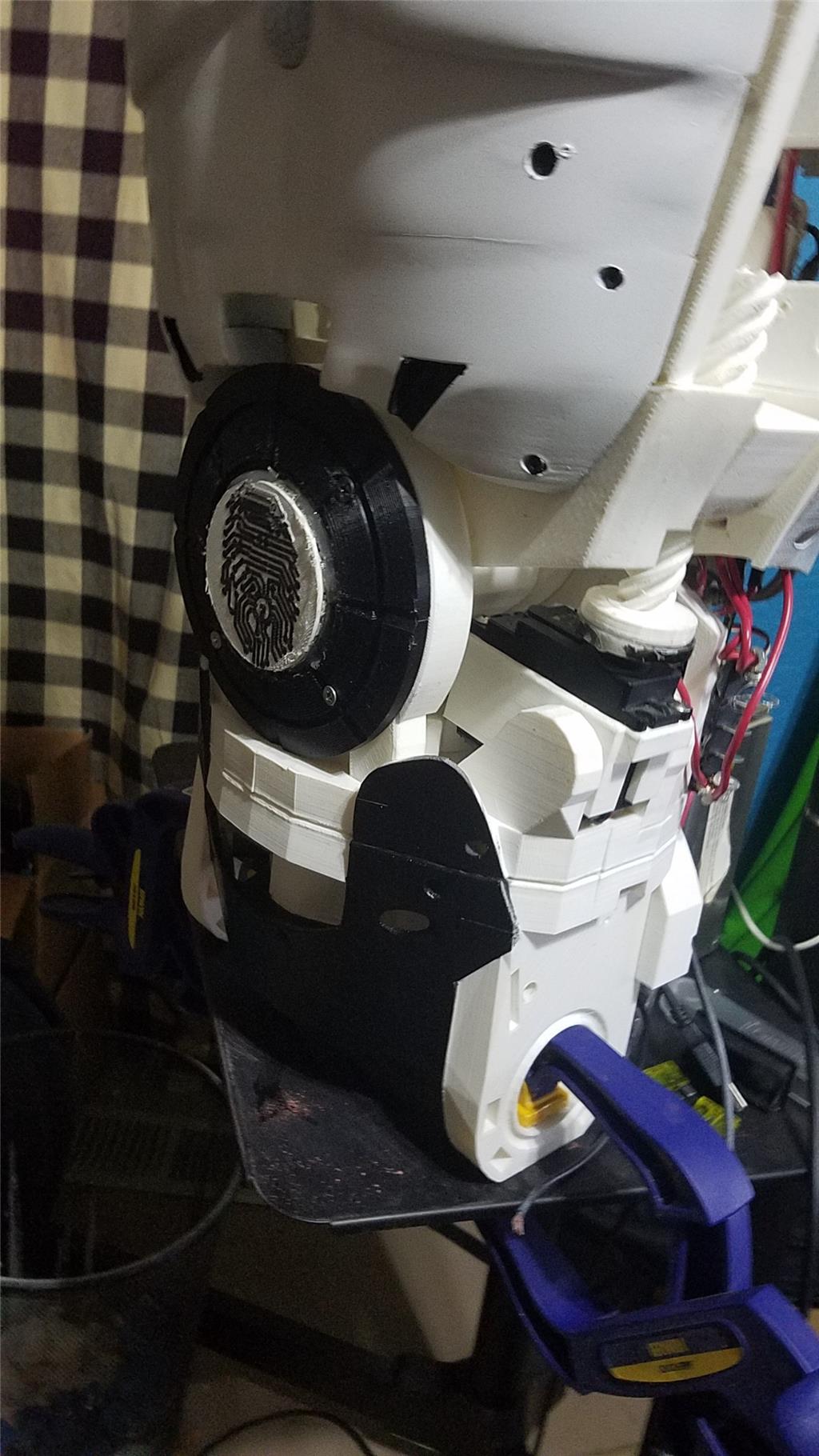
The Omron HVC-P is used to identify people, emotions, human bodies, hands, age and gender. It is attached to the Latte Panda via an FTDI friend which is then connected to the powered USB hub. It is mounted in the chest of the InMoov. I also use a 3 element microphone which is a MXL AC-404 microphone. It is disassembled and the board and microphone elements are mounted in the chest of the InMoov. This mic board is connected to the Latte Panda via a usb cable which is attached to the powered USB hub. There is a USB camera in the eye of the InMoov which is connected to the Latte Panda via the powered USB hub.

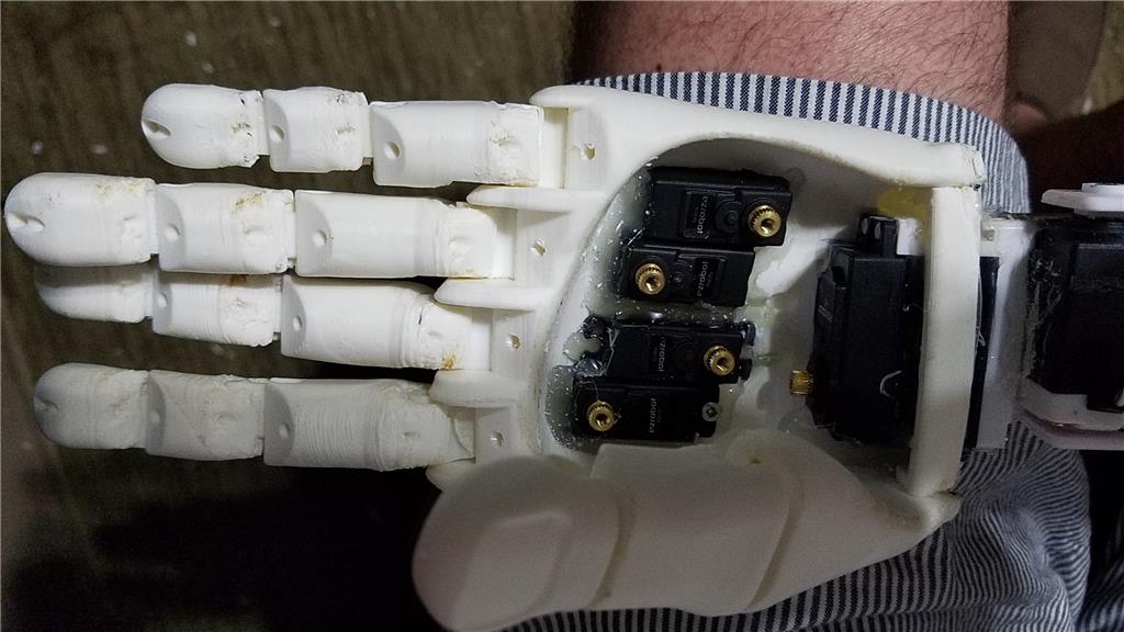
I chose to use the Flexy hand with the InMoov. The design is far more rugged than the original hand and works very well. There are 4 EZ-Robot Micro Servos in the palm of each hand which controls the main fingers. The thumb is controlled by an EZ-Robot HD servo. The wrist waves and uses an EZ-Robot HD servo to do this motion. I use the standard Rotational wrist.

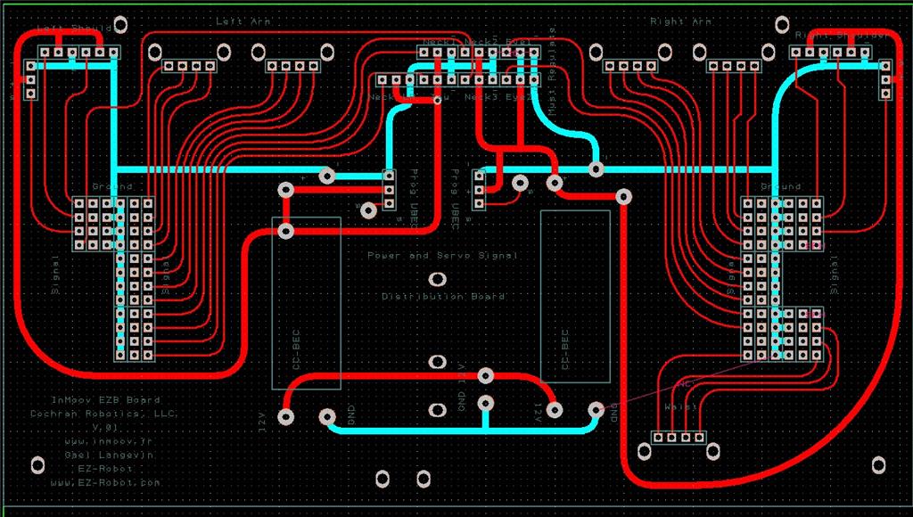
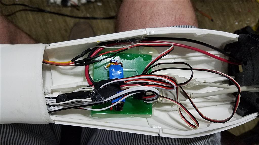
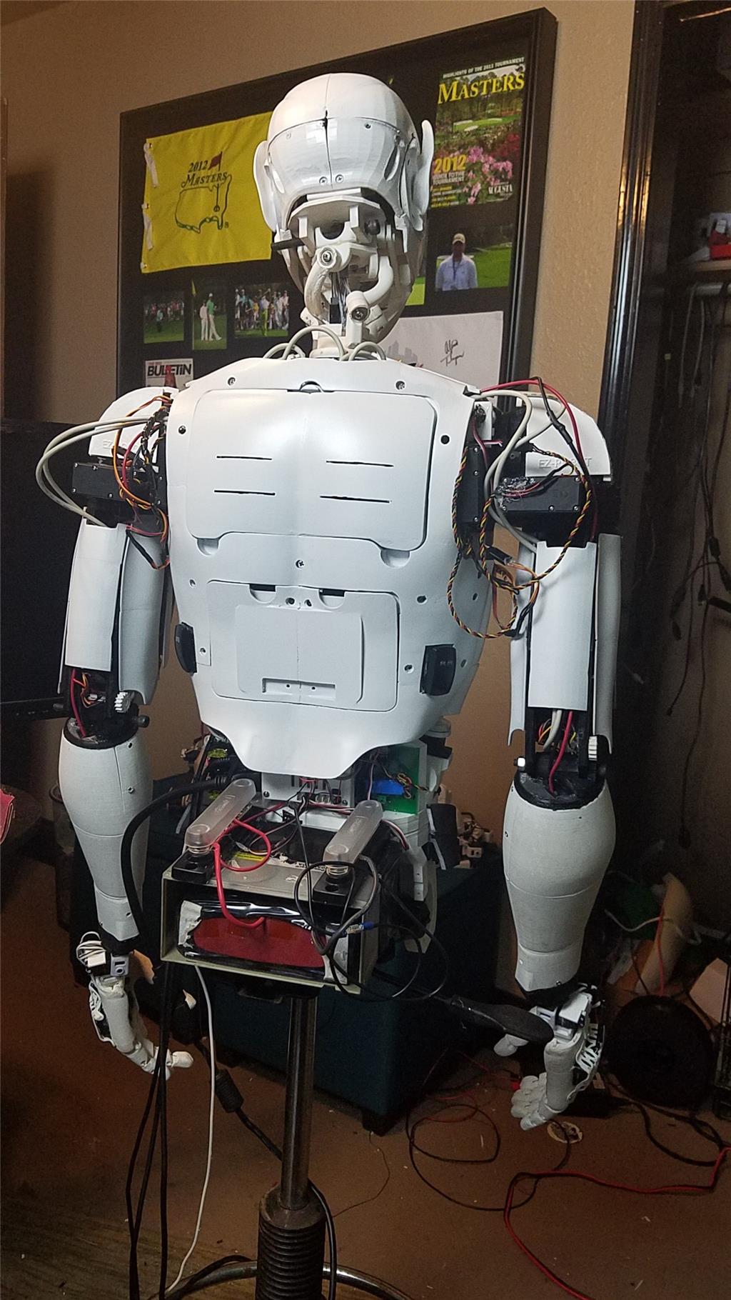
I have castle BEC's for power in the following locations set to the following voltages. Forearm's - 6.2 V - Controls fingers, wrist and elbows Custom power distribution board (2) set to 6.2 V controlling head, neck and Shoulder servos. EZ-B's - set to 6.1 V - it is mounted in the controller mounting plate and connects to the EZ-B fused power boards from a power base. Latte Panda - Set to 5.1 V and is mounted to the EZ-B controller mounting plate. Waist - set to 6.2 V and is mounted in the lower right side of the back. This provides power to the lean and pivot waist motors..

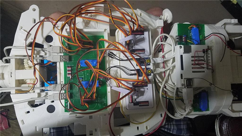
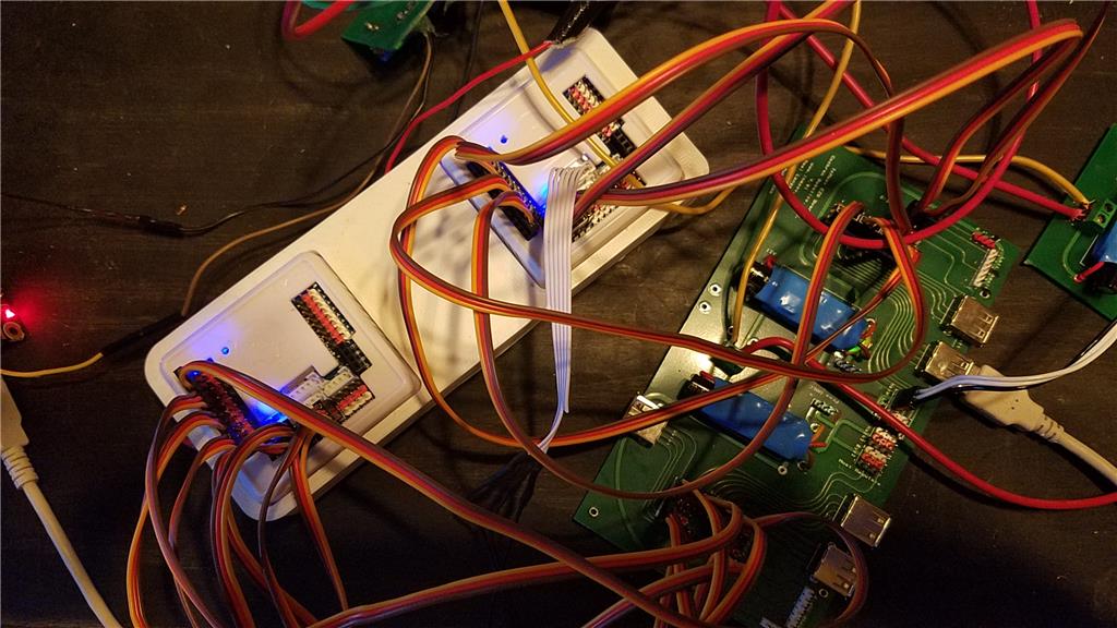
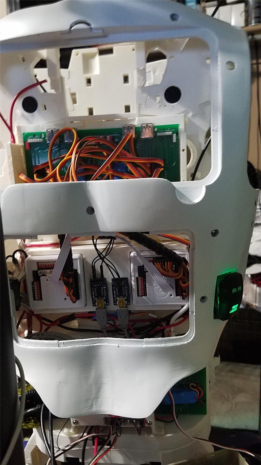
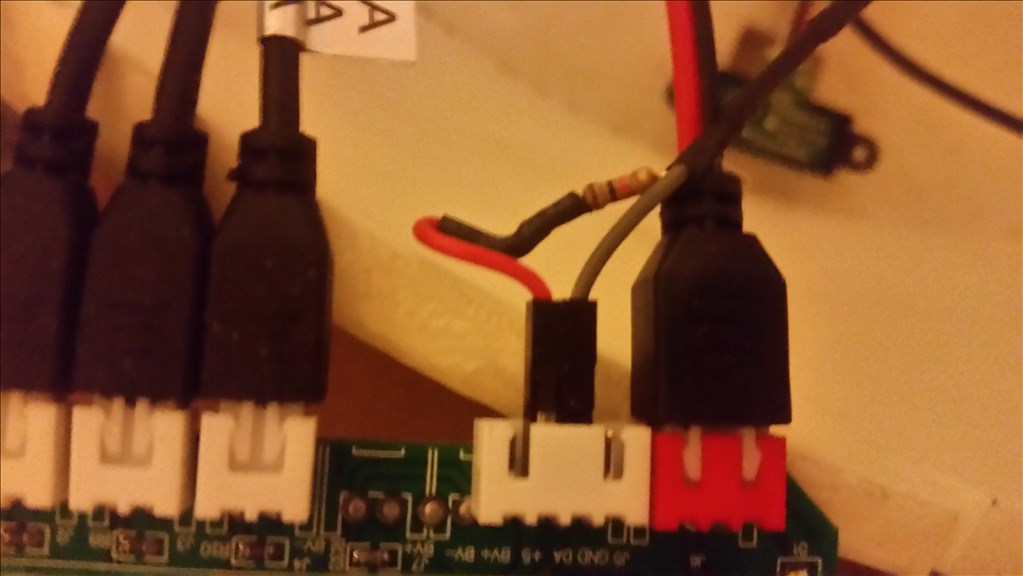
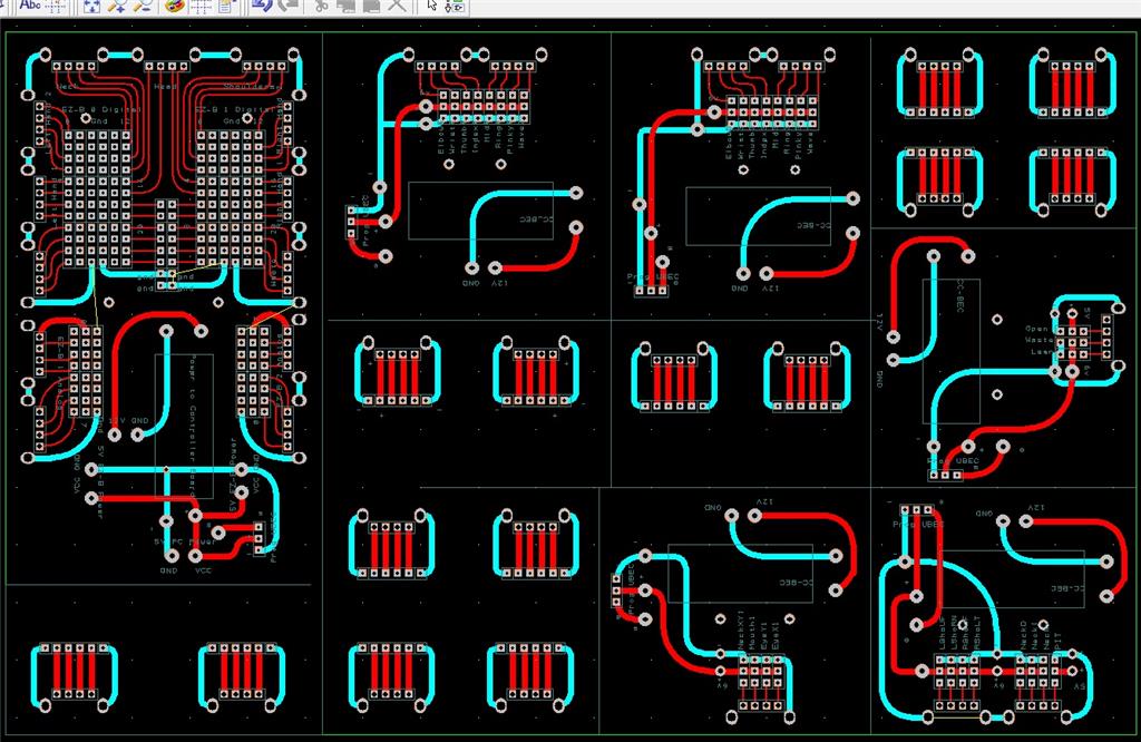
There are some custom power and signal distribution boards. These are in the forearms, lower back and in the upper back. The upper back or main board connects to these distribution points via USB cables to provide signal to the other boards for servos. The main board also has servo connector pins that are for the neck, head and shoulders. This allows the power to be distributed between multiple BEC's and also allows the servo signal cables to be shorter and more protected via the USB cables.

For power I use a LiFePo4 battery that is rated at 30 amps. It has the balanced charging circuit built into the battery and also has a low voltage shutoff built into the battery. This protects the battery and allows the battery to be charged with standard car chargers.

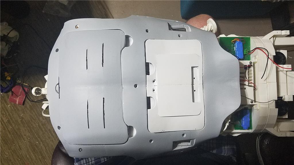
I put switches on the back on the InMoov which are rated at 20 amps at 12 volts. These are rocker switches that allow the user to pretty much slap the switch to turn it off. There are two of these switches. The servos for the elbows and fingers are on one switch. The latte panda, neck, shoulders, EZ-B's, waist motors and some lighting is on the other switch.

I also added a fuse block. This allows 20 amp fuses to be put in line to help protect things. The switches above drive the fuses for each of of the motors listed in that section.

User-inserted image

User-inserted image

User-inserted image

User-inserted image

User-inserted image

User-inserted image

User-inserted image

User-inserted image

By — Last update

ARC Pro

Upgrade to ARC Pro

ARC Pro is your gateway to a community of like-minded robot enthusiasts and professionals, all united by a passion for advanced robot programming.

#1  

@David.... Looks like you're officially committed now.... Hang on while I make some popcorn then I am all yours.... This thread is going to be even better than watching old episodes of Macgyver :)

United Kingdom
#2  

David, I am so glad that you are sticking with a robot build, your input into this community is great and I think a big build like this with your skill set will be awesome!

I am happy to donate Bosh servos, sensors, electronics and other stuff to your Inmoov build if you want? I think the Bosh servos (if converted for Inmoov) would make a fantastic improvement on the arms as the are virtually silent have zero holding current and have great torque.

If you want to make direct contact to discuss anything that you may need then here is my email address

toymaker(dot)tony(at)gmail(dot)com

Tony

#3  

@Tony.... The inmoov uses worm gear type gearboxes and a piston like corkscrew mechanism for the elbow joint... Although the Bosch motors would work better than the modified Hitec HS805bbs the arms as it stands now(because of the worm gear) don't really need too much current at all to hold their positions.... What would really improve with your bosch motors is the noise... Some of my large servos do buzz and it does get annoying after a while....

#4  

@richardr, The motors usually buzz if they are digital. Analogs have smoother action and do not buzz I understand. Of course, when I ordered a heap of them, I got digital. I always find out after the fact by making the mistakes.

#5  

@MovieMaker... No offence Mel, but you're educating me on servos? I was pretty much born with them in my hand.... The Hitec HS-805bb are analog servos and they are the ones that are buzzing... Their pots have been removed and relocated to the pivot point of the inmoov's joint... Because of this they don't position as accurately as they would if left unmodified... Hence the buzz... The digital servos I have in my inmoov's hands are dead quiet....

#6  

@Richard R, it's gonna be a fun build. I'm really looking forward to this.

@toymaker, thanks for the kind words and the offer. I will be contacting you later just to touch base. I would love to see what I could do with the servos. I love the design of them. I can think of multiple places that they could be used. I would also love to talk to you about the bumper proxy sensors you used. This robot will be used in populated areas around small children, and will be a mobile robot. That makes safety and a decent sensor array pretty important. These are all things you have already considered and handled.

United Kingdom
#7  

David, I was also thinking about my ultrasonic array sensor hack for your Inmoov build. As the ultrasonics are from car reversing sensors they also work great outside and do a really good detection job.

If you do not mind me enabling code protection on the custom PIC for this, I could send you out a couple. I have to use code protect as I am doing this development commercially so cannot afford to just give away my work as it will probably end up getting used in competitors product.

What the PIC does is to convert the odd "bit bang" serial from the reversing unit's control box and converts it to I2C which can be easily read by the EZB v4 so you get the distance in meters for all four detection zones. These units are so cheap at around £10 (with weatherproof sensors) and good quality build, they work really well for a wide angle (4 zone) ultrasonic sensor array. My PIC also sends out all the distance data to a I2C LCD display as you can see below, this is very useful in setting it all up.

User-inserted image

I not sure all the different car reversing units have the same "bit bang" serial, I get the feeling some may be different, so some may not work with my PIC. As the unit I used was so cheap, I did order 5 units off ebay and have a spare that I can let you have so you know it will all be compatible.

Richard R, same offer for your Inmoov build if you are interested?

Tony

#8  

@Tony, that would be awesome. I will definately take you up on this offer. I haven't even made it out of bed this morning yet. When I do, I will send that email I promissed earlier.

Turn on code protection. I have actually taken my source for EZ-AI off my site. It is getting pretty powerful and I don't know where it is going so, I might keep how I am doing some things a secret. I will always give away the compiled code or a version of it if it goes far.

#9  

@Tony... You're a generous guy man!... I appreciate your offer, but I am good with my sensor setup right now..... Thanks so much anyway.... :)

#10  

hey David this is more question for Richard do you know the tower pro at does it have the round pot or the square pots.

although I'm thinking I'm still going to print your boat that way you have both just in case.

also the HDMI cable you want to make sure you get the thinnest cable possible if you want to go to the arm because the way it rotates and a potometer holder could get in the way.

#11  

@Merne Do you mean the Tower Hobbies TS-80 Giant scale servos? If so all the ones I bought had the square pot...

Richard

#12  

Thanks merne.

Update to this project. The computer is built and I'm installing windows updates now. I'll record a video of the install of ez-ai on this machine, but it has a 7 inch touchscreen on it, so I might fudge a bit.

#13  

@Richarh R. yes thank you.

David i am going to print both round and Square just in case the manufacure changes pot again.

I bet that pc is going to scream. Fyi the head is none printed. i printed all 3 ears so you can choose which ones to use with your inmoov. man there is a lot of part when just printing and not being able to build it. : -)

i have started the bi-ceps abd should be completed by tomorrow night. it is getting closer. yea!

#14  

also David you might want to think about how you want the chest to be on inmoov, because I need to know so I know what parts and how many to print out are you going to use kinect or not and if you want to go like mine or Richards or Bob's inmoov or d.cochran's style inmoov. :) Thanks

#15  

I don't think I'm going to use the kinect. Please just do the normal chest.

I'm having issues with the bluetooth connecting to the mini keyboard. Actually, the bluetooth doesn't connect to any of my devices so I'm trouble shooting that.

#16  

well, that fight is over. A Microsoft update fixed the issue. I am typing this with the mini blue tooth keyboard.

#17  

okay I'm going to have to send Gael a email asking him if the first toroso without the connect holes are the same pieces / compatible for the new inmoov.

Richard might have an answer. Richard did you use the Kinect torso or the original torso without to connect hole?

bummer about the Bluetooth.

#18  

nice I'm glad you got it going.

#19  

Okay, well tomorrow I will work on wrapping up 1.0.0.5 if EZ-AI. I can test out the install and make sure everything works as expected on this PC. After recording a video of the install, I will publish the new setup procedures for a Windows 8.1 machine. Merne and I did find one thing that is different on a Windows 7 build and I will mention that on the video. I will also record another video showing the GPS module running. I will also record a video for this build showing the components that were chosen so far and how the computer reacts to things in ARC and the other things installed.

I can say that working off of a 7 inch screen and a six inch keyboard/touchpad combo keyboard is going to take some getting used to. I also have to design a small storage compartment in the robot to hold the stylus, keyboard and remote control for the monitor. So far so good on this part of the build though. I'm impressed with the speed of this computer in all aspects. A cold boot up is very quick and a wake up is only about 1 second.. I will show that in the videos I record.

#20  

I just timed it. A reboot right now takes about 10 seconds total. It takes 4 seconds from off to asking the user to log in. I will take that. Once other services are added, the time will get a bit longer, but not much. Very workable in a robot.

#21  

So far, I have decided to do without a couple of components, mainly because they aren't needed.

The touch screen listed was giving me some issues, but downloading the drivers from the vendors site made a huge difference. The monitor came with a 90 degree HDMI adapter so that wasn't needed. Because this is working so well, I am stopping my battle with the bluetooth radio on the motherboard. It can win, im good with it. This causes me to not need the mini keyboard, which too works great on everything I try it on except for this computer.

I will be using my robot outside during the summer months. Because of this, I have opted for a very large CPU cooler on this motherboard. If the robot were only going to be used indoors, I would have stuck with the stock cooler. The stock cooler and the huge cooler both came with CPU paste so purchasing the Arctic silver was unnecessary.

The speakers are under powered so I am sure that I will eventually replace them with something with a little more power. I dont know what that is going to be at this time, but my brain is working on it a little and its not that big of a deal to me right now. It will be addressed once I take him outside and the sound from the speakers isn't loud enough.

The 2 EZ-B's have been ordered from EZ-Robot and should be here early next week. Other stuff is on the way from England and the 3D printed parts are underway. I think the base and power are the next things to work on while I await these parts, but I really think I should wait to decide on the base until after I have the upper part of the robot build complete. Power however doesn't need to be attached to the base at this point so I think that is the next on the list to address.

#22  

I am thinking about puting 5 EZ-B V4's in my inmoov. I have 5 of them and think it could offer some good benefits. Here is what I am thinking.

1 in each arm. This will reduce the number of wires that will be running to each arm and through the shoulder. The shoulder, elbow, wrist and hands would be driven off of these. Also, I am considering placing the v4 camera in the hand to help with picking up objects or moving the arm and hand to the object to grasp.

1 in the head used to drive the Eyes mainly. I would probably add other sensors and also drive some sort of lighting to try to change the color of the eyes.

1 in the chest used to drive the waist and neck servos, some sort of lighting in the middle of it and possibly interface via serial to an arduino for whatever I can figure out to do with it.

1 in the base. This one would be mainly used to drive the proxy sensors and the sabertooth/kangaroo combo that will handle the mobility. I would probably add more sensors here like gyros and the like.

I want to add a total of 4 or 5 v4 cameras. 2 in the hands, one high in the back of either the head and/or chest, and one in the base. There will also be 2 cameras connected via usb to the eyes and 2 usb cameras in the front of the chest above the screen.

The computer will be onboard and will have a usb GPS, 4 usb cameras and speakers.

Am I just setting up far too much complexity with this layout to save on cables through the joints, or is this something that I should steam forward with? I know the scripting in ARC would be a bit more complicated, but not that much. Separating things out to various controllers (1 for each major body part) is logical but am I going to run into issues using the controls such as the Auto Position control? I might just have to script all of the movements I guess. I dont know. What are your thoughts?

#23  

d.cochran, I use this method in my B9. At one time I had 3 EZB's but down scaled to 2 for now. I'll probably end up with one or two more. It really cuts down on the wires running between moving parts. They all work so nicely together.

EDIT: It's really not complex at all. You just have to remember what EZB is where, It's number and what it is hooked up to.

#24  

Go for the complexity. Since you've got the EZB(4)controllers in hand layout what you can and build some scripts, make some tests and see how far you can go with your hardware. Remember benchmarking can be your friend in this endeavor.

#25  

Thanks guys. Dave, I agree. It's easier in a way I guess. 0 in head, 1 in chest, 2 right arm, 3 left arm and 4 base. The more complicated part (I think) is that it pretty much eliminates the possibility of using the Auto Position control. Other than that. It won't be bad. In a way, it makes identifying what I am doing in scripts easier. D0 for thumb, d1 index, so on with two of the v4's. Very few servos on the other controllers. Knowing or remembering what port goes to what becomes much easier.

Canada
#26  

Each arm including fingers / wrist / elbow / 3 servos for shoulder, total 10

Each arm will have 2 cables. One individual power cable going to power supply One HDMI cable ( 20 available connections) Connected to EZB at the back One EZB controler should be enough to drive 2 arms

Still there are 10 extra connections on each arm available for sensors or other

The inspiration comes from Markus in Youtube

HDMI connection in Inmoov

User-inserted image

User-inserted image

#27  

I was looking at using the HDMI cables but realized that if I could fit a v4 in the arm, this would eliminate the need for the hdmi cable. I love what he has done, but want to take it one step further:) . I will probably use the hdmi breakout device he has used. I plan on running one power cable down the arm to a block in the arm. From there I would split the cables on the servos out to power them from the block along with powering the V4 that is in the arm from the block. I would take all of the servo signal cables and run them to the digital signal pins on the v4 that is in the arm. This would take the number of wires that are passing through the shoulder down to 2 (one positive and one negative power). This would be easier to hide in the shoulder.

The other option is for me just to power these 10 servos off of the v4. The only issue that I have with that is that the large servos especially could draw quite a few amps on startup.

I had the extra V4's laying here and thought that if I used them for this project, I could reduce the length of the wires which has its benefits in multiple areas. I am trying to see if there is room in the upper arm to house the V4 and the wires that would need to go to it. I realize that this will add some weight but really this is small if placed high enough in the shoulder. I would probably use the run of hdmi cable to pass through the elbow and provide power and signal to the hand servos and the rotational wrist servo.

This solution would make the inmoov more modular. I would also put a power connection at the shoulder so that the arm could be removed as one unit and tested as one unit. I would do the same with all of the other body parts making the inmoov effectively 5 separate robots working together through ARC, which can use up to 5 EZ-B's in the same project.

All of this does depend on if I can find a location to house the V4. If I need to, I will remove it from its case. The V4's have been modified to not use the mini deens connection for power.

#29  

I am thinking about adding 5 arduino mini's to this project, 1 for each EZ-B. I would use these to do things like control neopixel rings or strips for some cool lighting in different areas. I would also use the ones in the arms to add touch sensors to the fingers or hands of the InMoov. I don't have a lot of experience programming on Arduino but there is no time like the present to learn, right?

#30  

David, If I can do basic programming on arduinos you will excel at it... It is basically C++ and their is a ton of example code all over the internet and within the Arduino IDE itself...

#31  

Is there a difference in mini's? I find quite a difference is prices. Trying to figure out what the differences are. The only real arduino experience I have is from the controller on my 3d printer. That really doesn't count... :)

#32  

Here's a Arduino URL that may give you some additional info about the choices available.

#33  

Yea, I can find them for anywhere from about $5 each to about $15 each. That seems like a huge range in price to me and there has to be a reason that some are $5 and some are $15. I know some are knockoffs but as with anything else, it is hard to know if this is an issue or not. Arduino is open source so knockoffs aren't such a bad thing unless they don't work with something.

Doing a lot of research. You know, robotics takes you in directions by noon you never conceived of at 8:00 AM.

Canada
#34  

If you can't find enough room to fit the EZB into the bicep, here is a nice place to sit the EZB Still part of the arm with no negative weight effect, Acessible and hiden from the front . User-inserted image

#35  

Okay, order has been placed for a mini, the FTDI board and a neopixel ring. I will see what I can do with it before diving into adding one for each EZ-B.

#36  

If you buy the Arduino mini you will need this in order to program them... USB to serial adapter I believe the micro has it built in...

EDIT Never mind I see you already knew that... :)

#38  

@Aerius, Great idea. Thank you!

@Richard R, Thank you anyway! I do appreciate it.

#39  

@David...Yep, I am pretty sure they are the same thing so you're good...

#40  

I have been updating the original post with parts as I receive them. It isnt a complete list yet but it is growing. I will keep updating that first post as I get new items.

Today I should receive all of the 3D printed parts (Thanks @Mernie). The package is 22 lbs for all of the parts. There are some extra parts being shipped but I would estimate that the 3D printed pieces of an inmoov will weigh about 18 lbs.

Example LiFePo4 battery - These are listed at 12V but I suspect they are actually more like 15 to 12 volts. I guess that they could have a regulator built into them, but I haven't done enough research on these yet to know.

There is a 12V 100Ah LiFePO4 battery also that I am looking at.Another battery example

I am considering changing out the batteries for lipo 12V(?) 35AH batteries. These batteries will be more expensive but will weigh about 1/5 the weight of the SLA batteries and will last about 4 times longer. This should allow me to reduce the number of batteries that I need down to 2 lipo's instead of 6 SLA batteries. This takes the weight down by about 100 lbs for the robot. By doing this, I should be able to use 12V motors instead of the 24V motors for movement of the robot. This in turn reduces more weight. The frame can then be reduced in strength which reduces more weight. All of this should allow the batteries to last longer with far fewer batteries and provide more power to other components. An additional benefit to the lipos is that they can deliver far more amps at any given time. This should prevent any brown out situations. If I went with the 100Ah battery above, the cost would be pretty much a wash as far as SLA battery cost vs one 100Ah LiFePo4 battery.

These batteries cost about 5 times what the SLA batteries cost, but if I am purchasing 1/3 the number of batteries, and the cost of the motors for moving the robot around becomes 1/8 the cost of the monster motors that I was going to have to use, and the materials to build the base cost much less, I think I actually save money by using the far more expensive batteries. I will have to regulate the 15ish volts down to 12 volts, but 25A 6V and 10 amp 5V regulators that I currently have should handle that without any issue. I will need to use a couple more (for 15ish volts to 12 volt for the PC and the motors).

I have also added a couple of 5 V regulators. The two 6V regulators will power the servos and the EZ-B V4's. The 5V regulators are 10A each and will power the other things like scary terry board, arduinos, neopixels and whatever else I need to limit to 5 V.

The plan is to wire the robot so that there are 5 distinct zones that only have power running to that zone. These 2 wires will have a disconnect at the start of each zone. This will allow there to be only two wires running to each zone (ground and voltage). Each zone will have a V4 that will operate only that zone. This should allow all of the wiring for each zone to be nice and tight. The arms use HDMI breakout boards to connect the V4 (which will be in the shoulder) to the lower arm with a majority of the servos. This will allow only one cable with 20 pins to pass through the elbow. I am not yet sure if I will also need to pass power wires through the elbow to the lower part of the arm or if I will be able to pass this through the HDMI cable. This layout should allow short jumper cables to be used from the V4 to the HDMI breakout board. Other signal wires would also be limited in length due to the location of the V4. Shorter wires are a good thing and keeping the wires out of rotating joints should also be a good thing.

I might also dye some of the parts. I think I am getting all white parts which is great, but I want to add some color to some of the parts. I could either paint or dye them. I will test dying on some parts that either won't be seen or won't be used. I will post pictures of the dyed parts. I have done this with nylon parts before with great success but have never tried it with PLA. I guess I could try it first with one of the EZB power bases that I wont be using to see how it looks.

#41  

I have some cleanup to do but here is the chest of my InMoov

#43  

d.cochran, Very nice, your InMoov will be very unique.

#45  

David... That's outstanding work already!..... Did Merne print those chest pieces for your tablet? I have never seen them before. They are not standard issue inmoov that's for sure. Any chance I could get those chest .stls from you?

#46  

Merne did print them. let me see if I can find them and I will shoot them over to you.

#47  

Email sent. This was designed to work with the monitor that I have listed. I had to modify it some with my dentist drill as you can see. Some of the pieces could be combined. I cut the top out to work with the Logitech cameras listed. They will be used with my 2 camera distance measuring component of ez-ai.

#48  

@David.... Thanks.... I have an idea of a use for them....

#49  

A 7 inch table probably would have no issue fitting these parts. It would also be easy to adjust the size of these parts to fit other sizes.

#50  

@David, one word WOW. You have done an outstanding job and very thorough on thinking things out. Gives me the itch to start something like this.

Can you share the .stl files with the rest of us?

Also, how much did it cost to get everything printed?
Was there a mixture of abs, pla and nylon?

For small computers I have used 3 of the iView's. Hard to beat them for the price and they run a very long time on a 5VDC battery pack.

#51  

The stl files were given to me by a friend in Russia in return for making EZ-AI work with MyRobotLab. I still need to finish that piece for him but also need to check with him before making them publicly available.

The printing was done by Merne on this forum in exchange for getting EZ-AI up an running on his computer. He printed all of the parts in PLA. The cost I had was shipping of $85.00.

The pc I went with was because this robot will contain my primary database for EZ-AI. My other robots will run off of this database. I opted for more power so that the database would perform well. It is a power hungry solution but one that allows everything on my network to work great.

As far as an inmoov build goes, it is fun and frustrating at times. It shows your the flaws in 3d printing very well. Every part so far takes sanding and modification to fit correctly. I have the torso, shoulders and bicep structure about 90% complete at this point. Superglue is your friend and you will use a lot of it. It makes you appreciate the injection molding process.

I would do it again at this point. I also will be buying a 3d printer but will be opting for the most precise one I can afford. MERNE'S solidoodle will get the job done for sure and I thank him for printing this for me. A more precise printer would be my choice when I go to purchase one.

#52  

@69developer Not to mention the chest pieces are no good to you anyway without all the other inMoov STLs.... The whole inMoov project (and all the stl downloads) can be found here... inMoov project

#53  

Where David has the 7" screen, I was possibly going to put a Dell 8" Venue. So I was hoping to start with something and just modify it a little bit. I have all the inMoov stl files downloaded but very few printed yet. Between helping my kids with ball season and letting them learn on the Roli and JD and me working on a mobile robot platform that uses mostly Phidgets, don't even know why I started thinking inMoov...... confused

#54  

I haven't heard back from Alex yet. When I do, I will be happy to share the STL files on my website and update this link. I just want to make sure he is okay with it first.

#55  

Understand completely, and thanks!

I think I am going to put a 7" iView Win 8.1 Touch screen there instead of my Dell. It only has 1GB RAM is the bad thing but for what I am going to be using it for, it should work out ok.

#56  

I have the stomach and chest built but I don't see parts to tie these two together. If anyone can point me to these parts, I would really appreciate it. The instructions get really poor when you get to the stomach.

Edit - found the parts. These are gonna be fun to get in place...

#58  

@d.cochran - if and when you get time, can you take a lot of pictures or real nice video showing close ups of the parts and how its assembled?

#59  

@David.... Nice! You assembled that very quickly.... I love the monitor in the chest it really works with the big guy.... Are you having fun yet? :P

#60  

Fingers glued together so typing is hard...

Its fun for sure. I think I will buy a printer and build another one already :)

#61  

@David Have you found a mobile chassis for him yet? Or decided on one? I am looking to replace mine (built it out of Vex).... Although it works well enough, my inMoov is a little bit too heavy for it... Motors are perfect, but I need a stronger chassis... I like the one Bob Houston built, but currently I am trying to design/build or buy a better one for mine....

#62  

I haven't gotten that far yet. It is on my mind a lot though. I think I will have to build one. It has to fit through doorways and still house the computer, battery, charger and some other thing. I am thinking about a multi-platform solution. I haven't really designed it yet though. The new parts from EZ-Robot look like they will help with a segway style platform but I dont know if it will have enough room for everything I am trying to cram in there.

The parts mainly fit together using a dovetail type connection. There are some screws but a majority of it is squeezed and glued together. It's not fun with some of the parts. I think that if I print another one, I will combine some of the parts so that they are printed as a single piece instead of pounding or squeezing them together. I have this picture of inmoov begging for me to stop hurting him.

#63  

@David... Since you said you may build a second one (I am almost done my second) I suggest using abs... Not only does it give you added strength but you can use acetone to bond parts.... Using acetone works so well the joint will actually be as strong or stronger than the rest of the part... Plus it is not messy at all to work with and makes a clean looking joint....

#64  

I completely agree with you on this. I have printed some abs parts in the past and used acetone to bond parts. As I put this one together I kept wishing that I could use acetone. As it is, I think I need to invest in Gorilla super glue with as much as I have had to use.

#65  

I remember cursing a lot when trying to attach the lower abdomen to inMoov's chest (both times)... LOL... I was mentioning to @DJ in another thread that if the new ez robot Inverted Pendulum could handle the current I would make a 2 wheeled balancing base for my inMoovs... :)

Canada
#66  

@David WOW your moving at a very fast speed. How many arms and hands do you have to achieve so much work in a short period of time. It's already looking great.

Bravo!

#67  

My child labor :)

Just kidding. This is my class helping with some of the build.

#69  

Placement of components on back of inmoov (may change).

There are 4 of the 5 EZ-B V4's, 2 12/24 V to 6V 25 amp regulators 1 12/24 V to 5 V 10 amp regulator 2 power bars (one positive and one negative)

Is this placement going to interfere with anything else in the build?

User-inserted image

#70  

I need to take a break from this project for about a week. My cousin is coming to town this weekend, my second grandchild is being born tomorrow and I will be watching my first grandchild tonight and tomorrow, it is month end and is a busy time for me at work, and the school bought a solidoodle 4 for my class and I need to get it printing ABS.

Sorry Spock my EZ-Robot InMoov, your gonna have to wait. Life got in the way.

United Kingdom
#71  

@David

Wow! that's a lot of EZB's, why do you need 5 to control the InMoov?

Cheers Chris.

United Kingdom
#72  

@d.cochran.

You have done a fantastic job so far with your InMoov. Great job. And that's great news about your second Grandchild. Yep, life has a funny way of throwing out the expected & unexpected and getting in the way of things. Anyway, keep up the great work. :)

Steve.

#73  

Thanks Steve G!

@cem, I dont need to use all of them but want to segment the robot out into sections. The right arm will be driven by the EZ-B on the right arm. The left arm the same. The bottom torso will be controlled by the one at the bottom and the head will be controlled by the one at the base of the neck.

The reason I want to do this are

  1. I want to limit the need for all wires to be run to the single EZ-B causing a hairy back.
  2. I want to be able to have the servos on the left and right sides easially identifiable. Thumb will be in the same digital port on both the right and left side EZ-B's
  3. I want to be able to limit the amount of current going through each EZ-B
  4. I want to use 5 EZ-B's because I had them laying on a shelf waiting for a use.
  5. There are 40 analog ports allowing for a lot of things like touch sensors.
  6. There will be about 100 free digital ports allowing for many sensors to be added.
  7. There will be 15 dedicated uart ports allowing for a lot of communications to take place to other devices like arduino driven things.
  8. Lastly, because it will be cool. :)

[edit] I forgot to mention the 15 I2C ports that will be useful with all of the new sensors that EZ-Robot is going to produce. I also plan on having 9 cameras on this InMoov. 5 of these will be V4 cameras, 2 will be in the eyes and 2 will be in the chest. The 4 non-ezb cameras are all usb cameras that will attach to the computer directly. I also will have a GPS unit on the InMoov for outdoor navigation which will connect directly to the computer. [/edit]

You dont need 5 EZ-B's for an InMoov. It can be done with one. Depending on your needs, you might need 2 at most. There will also be an onboard I5 with 16GB ram and an SSD. This too is overkill right now, but I will find uses for all of this.

#74  
  1. David wants to raise the inMoov "bar" so high that you'll hear a collective gasp from the arduino community. We can then witness the vast pilgrimage and migration of the hairy backs to the ez robot salvation....:P Behold the inMoov king.... You'll need to sacrifice arduino's to appease the Robot GODs

I don't know about you guys but I am going to be disconnecting my router at night as I am now afraid my inMoov is going to murder me in my sleep :P

Canada
#75  

I do not see a problem with the EZB on the shoulder servo as long as the power and control cable go through the shoulder's Pivgears. You may also hide your HDMI terminal into the shoulder or stick it under the servo where the EZB is.

It is going to be a neat design :)

#76  

It will be interesting to see how you program the robot's gestures, Dave, with all those EZB's. I have all of the servos on one EZB. I can use one Autopositon control to create gestures.

#77  

Yea, It will have to be scripted but I am good with that. The AutoPosition control wasn't around when I started with EZ-Robot:) This is the one drawback to me doing it this way, but I think the benefits outweigh the costs and I am sure that DJ will add the ability to use multiple ez-b's with the Auto Position control at some point.

#78  

@d.cochran Although the auto-positioner is a Godsend, I too like to script some of my movements... I find I am able to achieve more customization in movement routines that dare I say work better for that particular purpose than the auto-positioner...

#79  

Ya, It would be nice to be able to have servos assigned to different controllers in the same AutoPosition control but I'm OK with the way it is.

#80  

I have got to say that the solidoodle 4 prints abs well. It took some trial and error and about 1/10th of a roll of file filament to get the settings right but it printed it's first part and it looks pretty good. I plan on printing about 2 rolls of filament before calling it good but I have to say that I am impressed so far.

When we got the printer it had a screw missing that held the right side panel in place. The right y axis belt had slipped and the x axis set screw for the stepper motor gear was loose. All of these things were quick fixes.

To get it to print well, I am using an older version of slic3r and repetier host. I didn't have good luck with the newer versions of it. I have spent about 12 hours working on getting it setup and tuned in, but I expected longer than that. I will comment again on it after the 2 rolls of filament have gone through it without issues. I wish I could drop the money on simple 3d but this is the schools printer so working well is good enough for me.

#81  

I have been continuing to tweak the solidoodle 4 and have been able to print at .1 mm. The results were good.

There were another few issues though. The build plate is thin and uneven. I now have a piece of glass that is held with 2 paper clips to the build plate. It is flat and resolves the issue with the uneven build plate. The Z-Axis stop is held with two small screws that tend to loosen with time. I have used blue locktite to keep these screws from loosening and causing the printer to loose the z stop switch. This has pretty much made this printer a "click print and forget it" type printer at this point.

A couple of features that I wish it had were some way to control the printer from the printer itself and a way to use an SD card. I am investigating OctoPrint on a RPI to see if that will give me what I want out of this printer without messing up the good prints that I am getting from Repetier-Host. If not, a PC will have to be placed near the printer.

Prints continue to come out very nice with the exception of the occasional adhesion loss issues. Hairspray seems to have solved this for the most part. I am continuing to print parts for InMoov and will see if I can find a part that it has issues with. So far I am printing replacement upper arms. This seems to be the place that would have the most stress. I plan on printing pretty much another InMoov worth of spare parts to put on a shelf and wait for them to be needed. I am still impressed with this $600 8"x8"x8" build volume 3D printer.

#82  

That's awesome David.... The inMoov project is addictive that's for sure...I see that Simplify3d supports the solidoodle 3 so possibly the 4 as well?... It cost $149 or something like that, but is worth every penny IMHO...

#83  

Yep, if it were my printer, I would be buying simplify3d. It's the school's for my robot class. I'm trying to keep it as cheap as possible for them but it is seriously making me think about going this route for my own needs. I've held off on buying a printer until I saw what this could do. It's a bit slow but produces pretty good abs prints. I want to print the gear that you printed for me to compare the results before making a decision on what to buy for myself.

#84  

Gotcha' for some reason I though you managed to procure one... Sounds like you got a good gig going there... :) The worm gear I printed for you was printed at 200microns and is nearly solid abs... It should be very strong... The Up! printer can print to 150microns but I found 200 to be a good compromise between speed and quality. To be honest, parts actually fit better when I use 200microns...

#85  

Thanks for the info Richard. I like 200 microns also so far. 100 just takes too long and 300 is not quite as good of quality as I like.

I will see how many parts I can print before things start going south with it. The initial setup takes some commitment but it blows the doors off of my Prusa I3 that I built. I couldn't ever get it dialed in so it is being parted out and I will use those parts if I need steppers for a robot build. The metal frame and rods will probably be used in my InMoov base for something.

PRO
USA
#86  

I'm planning on buying the solidoodle workbench with a volume of 12 inches cubed. The price is very reasonable at $1200. Not many with that volume/ price point. I have 4 printers from sla, dlp, fdm the solidoodle 3 is a hearty machine, and stands up against the rest when I need abs mechanical parts. Glad you are enjoying the machine.

#87  

@ d.cochran. Where did you get these voltage regulators from? 12/24 V to 6V 25 amp regulators 12/24 V to 5 V 10 amp regulator

#88  

5 V 10 A

6 V 25 A

Most of the stuff for electrical is boat rated. I figured that it would be good to have some pretty water tight components for when he decides to go scuba diving :)

#89  

Thanks Dave, Waterproof is good, I'm thinking golf caddy.

#90  

Just a status update...

I am reprinting some of the pieces in black ABS. I need to align the left eye with the right one still. I have one lower arm done but think I am going to reprint them in ABS also. Pretty much everywhere that could need strength is being printed in ABS. PLA will work but I have the use of a printer for a while so I think I will use it to get the color scheme I am looking for. It also lets me have spare parts on a shelf incase something breaks.

PRO
Belgium
#91  

your inmoove is great love the color black/white

#92  

Today I got the head servos and the upper left arm servos working. I have a bit of a problem with the scary terry board but have a spare one so I'll switch them out and see if I have better luck with the other one. Fine tuning these boards isn't a lot of fun on an inmoov.

United Kingdom
#93  

I was just checking out your status update in post #91. Really great work so far David. Your InMoov is looking the business. I'm pleased you got the head servos working now, and upper arm one's too. Your build really has come along quite a bit in such a short space of time. Keep up the good work.

Great stuff. :)

PRO
USA
#94  

Looks great, moving fast!

#95  

The end of this video makes me smile. Sounds like the little guys on Toy Story who say "The Claw".

This is the back of my InMoov right now. There is a lot of wiring that needs to be cleaned up.

PRO
USA
#96  

Lol, the voices, make the voices stop in my head..

PRO
Synthiam
#97  

OMG that's awesome and creepy at the same time!

#98  

Yea, my daughter heard it and ask when the inmoov became possessed. I laughed because she doesn't realize what was happening.

She is kind of creeped out by the inmoov build anyway. I cant wait until its standing outside her door when she walks out of her room.

#99  

Ha, ha, that's funny David..... That's the reaction I usually get when people see my inMoov for the first time..... "That's so creepy".... after a bit they come around and are usually in awe of it being so life like....

#100  

I have decided to reprint the inmoov. I have use of a 3D printer this summer and figure that I might as well reprint it in the colors that I want. I am looking for a white and black scheme with my inmoov. Right now, my parts are natural white. I also want to print everything in ABS anyway. Because I will be doing a lot of printing this summer, I have decided to purchase Simplify3D. I have printed a couple of parts with it and am pretty impressed with the results. I haven't quite got every setting in it fine tuned but the default settings for my printer are better than what I could get with Slic3r and Repetier. I am still tweaking the settings while printing the parts and have been improving the quality with each part.

The main reason that I want to go with ABS is strength. It also allows me to use Acetone for part bonding which I like better than glue. The parts just come out more clean for me and also are bonded instead of glued, adding more strength.

This is going to take some time to complete, but I think it will be worth it in the long run. The current build is being used to test everything and allows me to experiment with wiring and other things. It also has allowed me to go through a build once already, which helps me to understand how the build works. I think that this understanding will help my final build to be more accurate. I will donate the current build to the school that I work with (minus all of the electronics) which will allow the students to gain an understanding of many different aspects of robotics. It also helps me to be more patient knowing that there is an inmoov in my closet that I can experiment with.

All of this is just to say that this build is going to take a lot longer than I had originally anticipated. All good for me as it is a learning process and I want to get everything correct.

#101  

I agree David... My inMoov is/was basically printed twice... I gradually got better at printing, sanding and fit and finish... So my first gen parts that I wasn't particularly happy with were reprinted to look, work and fit much better....

There is no hurry... There's a lot of work, no doubt... it's a great journey so to speak... What I liked about it the most was learning new disciplines a long the way... I can hack a servo with the external pot mod in about 20mins now... First one I did took nearly an hour to do LOL.... :)

#102  

Hi David,

I'm enjoying following your build and how it's developing. Your making some great design and build decisions. Looks like your having a lot of fun and learning as you go. Isn't that what life's about anyway?

As long as your rebuilding I have a suggestion for your build that may help. I noticed you are using some very large power regulators with big and probably heavy heat sinks attached to the back of you build. After reading the specs on them I cant really tell If they are Linear Regulators or Switching Regulators. Switching Regulators are usually smaller, lighter, run cooler, use and waist less battery power. Castle Creations has two Regulators that may serve you better. They offer a 10 amp peak and a 20 amp peak Switching Regulator. They are amazingly small, light and well built. While these two offerings handle a little less peek amps then what you have now you could easily run two and split your load.

Input voltage is variable and output is adjustable (additional hardware is needed to set output voltage through your PC but is easy to do).

I'm running two of the 10 amp regulators in one of my B9 arm and am very happy with it's performance and compact size. It weighs nothing and can be hidden almost anywhere. The 10 amp model has three wires on the regulated side but you only need two of them. Find the two the deliver the regulated voltage, clip and tape off the third.

I thought I'd mention this because in Robotics we always seem to be looking for ways to lighten weight, cut power consumption, have things run cooler and more efficient. I thought this may help you do some of this with your build.

Look over these specs in the link below. You may find if they are within your needs these two regulators may work better for you then your present regulators. You can find them on Amazon.

CC BEC Pro Switching Regulators

User-inserted image

User-inserted image

Castle Link Programming Kit (about 23 UDS on Amazon):

User-inserted image

#103  

Hey Dave. I agree that BECs will be a better option. I haven't made it to that part so much. I do plan on upgrading to BECs at some point. I wasn't sure (and am still not sure) if I will go with 24 or 12 volt motors in the base for mobility. As you know, this plays a huge role in what I use for voltage regulation. The ones I bought will handle 12 or 24 volt, so I opted for them initially to allow me to see test a 24 volt or 12 volt system. I want to go 12 volt for a number of reason and will try that first. If it works out, I will be able to make a choice on which BECs to pick up.

Thanks for following the build and offering suggestions. They are much appreciated.

#104  

Just a status update...

One arm built with new colors and a few changes to the colors on the inmoov body. I will be finishing the other arm and then going on to reprinting the head. A few of the PLA pieces (mainly gears) have broken. The jaw gear broke when I was fine tuning my scary terry board, so while I am fixing that, I figure that I might as well try to tighten up some things in the head.

As far as the solidoodle goes, I have printed about 3 KG of ABS through it. I think the results are pretty good. You get what you pay for and it is a $600 printer, but for $600, it does a really good job. I am still split on what to buy for a 3d printer so I am going to hold off until the end of the summer, and use this one until then.

Canada
#105  

Looking verry good, I lyke the stomac color mix.

#106  

New back of inmoov after other arm has been added. I am working on the reprint of the right forearm and on finishing up the left arm currently.

I have added 3 switches to the back of the inmoov. One controls the power to the left arm and head. One controls the power to the right arm. One controls the power to the lower body. This allows me to be able to kill power to the battery while working on the inmoov and also allows me to work on a zone at a time without having the other zones pulling power needlessly.

User-inserted image

There is still some wire management that needs to take place but I will focus on that as a last step of the build.

#107  

Hey Ant, the best way I have found to print it is with 2 shells and at .2 mm. The gears I print at .985% scale. I also use grease in the rotational joints.

The shoulder attachments that connect the shoulder to the arm are a pain at best. I haven't found a good way of getting them to connect without breaking at least one tab on them which is then superglue back in place.

I hope this helps. I had to battle the 3d printer today. Both of my z axis idler pulley brackets broke. I was able to get them glued back together long enough to make new ones. Printing again now. Hopefully this fixes the printer for a while.

#108  

The information was what I used to get prints that allow the parts to fit together as well as I have found, not only for the gears, but also for the other parts. The gears being printed slightly smaller has helped me. The gears work for me fine when assembled.

#109  

That being said (post #111), if you can improve anything, I am sure that the inMoov community would be most grateful as would I.

#110  

I am in the process of printing BHouston's neck mod. Hopefully it will be completed tomorrow and I can start adding it. I still need to print the covers for the right arm and about 1/4 of the skull. My hope is to have the skull and neck printed by this weekend and then I will finish the arm covers. I am waiting on one more HDMI breakout to complete the right arm. After that it is time to wire him up and see where any issues are.

User-inserted image

Also, my work area has moved out of my office and into the garage. There is motivation to get him completed before the hot summer starts...

#111  

Ha, ha... sooner or later we (us robot hobbyists) get asked (told) to move our projects to the garage or basement.... Spock is coming along nicely. Can't wait to see an all up test of him... :)

#112  

@D.Cochran - Your inmoov looks excellent and I can't wait to see it operating!

#113  

Arm covers are on the left arm. I will have to rethink how I am running some wires down the arm as these covers attach where I had the wires zip tied to in the bicep.

Bhouston parts have been printed for the neck. I'm just waiting on the Pistons to complete. I am thinking about changing out these piston gears for linear actuators but need to do more research. I also want to look at changing out how the jaw gear works. IMHO the design is over complicated for what it is doing.

#114  

So, as things go with robots, I started working on one thing and quickly got distracted by others...

The monitor now is powered off of the robot's power center instead of the power inverter that it came with.

The Scary Terry board is now hard wired instead of using the barrel power adapter that came with the board. I had a spare Scary Terry so I figured if I messed something up, I would just use the spare. It was on its own circuit anyway so I wasn't worried about messing up anything else.

I have printed bhoustons parts for the DOF head and have started assembling this. The parts work great so far. I will be modifying the servos that I am using to make them work similarly to the waist. This will allow one digital pin to drive two servos that will be working in unison for the head tilt.

I got the wiring figured out and routed for the left arm with the covers on it. I made the same changes for the right arm. I will be printing the arm covers for the right arm in the next 24 hours or so. After that, I will finish printing and sanding the rest of the head. Hopefully by next weekend, Spock should have a completed upper half and I can start doing some testing and fine tuning.

I just received email notification that the HDMI socket breakout board is on its way for the shoulder of the right arm so, my hope is that it will be here by next weekend.

I also received an email that the pots that I am going to use should be here tomorrow. I like the thought of a round pot as I can rotate it in place to get the exact correct position prior to securing the pot permanently.

I got a lot done today but there still feels like there is a long way to go, but I am enjoying the journey.

Canada
#115  

@D.Cochran I am still looking for the round pots, can you share a link?

#117  

@Aerius, I got these through an unconventional means... Let me see what I get and then I would be happy to mail you what I don't use that would work in the inmoov.

Canada
#118  

@ Rich & Dave Tanks guys, I appreciate :)

#119  

Well, tonight I got Bhouston ' s dof neck installed. I have to adjust the placement of a couple of components but that won't be hard to do. I also got the right arm covers and the rest of the head printed. I was making good progress today until...

I broke his left arm at the pivot. I moved him while working on him and heard a snap. I am trying a repair but think I am going to have to print a new upper left arm to really get it fixed right. Ugh. I hate putting together the upper arm. This will be the 5th time putting one together for me.

I got the pots and am thankful to the person who sent them to me. I need to remove the square ones that I dislike and still plan to have the upper body build complete by the weekend.

#120  

@David.... That sucks.... I blew a shoulder gear box (twice) from trying to move servos beyond inMoov's joint range (once was an accident, twice was just dumb LOL).... Frustrating... Worse is I had 2 servos burn out (within a week of each other) for no apparent reason in the left wrist... In order to replace the wrist servos you have to remove all the fishing line from the forearm servos...

@Bob's new neck design is pretty good.... Eventually I will put it on mine as well...

Canada
#121  

@David Sorry to hear that these parts break easily. I know by experience that the handling error margin is thin.

I am still working on BHouston neck mechanism. I'm almost there

#122  

@Aerius, The part broke because the hand was caught under something when I tried to move the entire robot. I guess this is better than breaking at the wrist and having to rerun all of the strings and such.

I have access to a 4 axis CNC machine that can cut out aluminum. After I complete this build, I will experiment with making some of the joints far more durable by having these parts made from aluminum. It will be a while before I am to that point though.

Canada
#123  

Aluminum, that will be great, But no matter how robust those parts are, I believe we still need some sort of feed back to gain control of all articulation. I am presently working on finger feed back mechanism found on thingiverse http://www.thingiverse.com/thing:92352

Hope I could apply it to arm and shoulder articulation.

#124  

That is cool. it is the first time that I have seen this. I think I try to incorporate this into the left hand when I finish getting the head and left arm rebuilt. Thanks for the info.

#125  

Wow, that sucks D. I bet your heart dropped into your shorts when you saw the break. A stronger joint is certainly called for. This is the downside of 3D printing that scares me. A little too fragile for my current needs. Do you think the added weight of the aluminum will cause problems for the servos trying to lift it?

#126  

I plan on using them in at the top of the arm. I may have to go with linear actuators but all of that is a ways off. For now I used an acetone ABS mix to strengthen the upper arm. I am also using this on the skull right now to make it look like one solid piece (which I guess it will be when it all bonds).

It sucked but lesson learned. This is the thing I really like about ABS. Being able to build up parts is really nice.

Edit There are little gaps between the pieces that will be gone when I am finished. There are some very visible parts to an inmoov. The head is one of them for sure.

Also I doubled the infill that is suggested. This should make the parts stronger.

#127  

Left arm replacement complete. Working on the head now.

I found that a lower stomach is available on thingiverse. I see that Bob is going to build one. I think I will wait for a bit and finish up what I have before adding more. The good news is that I already have a v4 at the lower back that will be able to drive the servos for this. It is practically unused at this point.

inmoov lower stomach

As far as my head goes, I ordered 2 180 degree fisheye lenses for the eyes. They should be here in the next couple of days. I will build the eye mechanism when I get those. They match some eyes that I have printed. Until then, I will work on the alignment of the eyeglasses and upper lip piece with the head. The head is being built and painted kindof like you would do an old enamel paintjob on a car. The paint is used to fill in the imperfections and then sanded back down. Right now there is a little too large of a gap between the eyeglasses and the bottom of the forehead for my liking when the eyeglasses are screwed in place.

One more thing that I found on thingiverse... There are vulcan ears, and since this is spock, well it is only natural that I print them out, so that is what the 3d printer is doing now.

#128  

looks like I am going to pass on the vulcan ears. I dont like how they look printed mainly because I loose the holes that are around the ears. I have plans for those holes.

Canada
#130  

You're almost done. It looks just great. I am still impressed how quickly your project goes. I am still working on the 3 piston neck mechanism, due to the extra weight brought by the EZB installed in the head, the front attachment tends to pop out too easily.

#131  

@Aerius, Post any questions or problems you have with my neck mechanism on this thread https://synthiam.com/Community/Questions/7787, and I'll answer them there. That way other people that are building it and not following this thread, can benefit from it.

#132  

I am reprinting the chest in ABS so that it will look like one solid piece while I work on the face and head fit. I dont like the lines around the eyeglass piece so I am building up and sanding down the eyeglasses so that they fit really well. The main focus is the top and bottom of this piece so that when it is finished, it still can be removed, but will have very minimal lines.

#133  

tonight I will start wiring up the v4's and testing some things out. I did have one of my large shoulder servos bind and burn up. I guess I didn't realize when it happened that it did happen because I haven't have this guy plugged up to power in weeks and just discovered the locked up servo yesterday.

There is still some finish work and polish to the paint on the bumper that needs to be done but I have been painting and sanding for a week and am ready to do something else. I will come back and finish this up in about a week which will let the paint get good and cured before I start my final sanding.

Will post a video when he is all functioning.

#134  

I will be taking a step back from this project for a couple of weeks. I will do some small things here and there, but I have taken off work the week of the 22nd to focus on completing him (the top half anyway).

In getting the servos running through ARC, I ran into a couple of snags and wiring issues. All of them are minor but I want to have some dedicated time to work on him without work getting in the way. Also, a couple of small parts broke when first moving them and I am out of filament again until Tuesday.

On a side note, my wife started taking a furniture upholstery class and is pretty darn good at it. It looks like I may putting air conditioning in my garage so that she can work on her projects :).

I have a question though... What are you guys using for a stand at this point? I assume you are using an aluminum pole attached to some sort of tripod base. The table that I am working on doesn't allow me to work with the arms much, so any suggestions of what works well for you would be appreciated.

#135  

An old milk crate and some zip ties seems to do the trick of getting my upper body high enough to work on the arm servos. I will worry about pretty later but this gets me moving forward.

#136  

I have been thinking about what I am going to do for a mobile base for the Inmoov.

I am thinking that I will buy this set table and chair set

I would put wood between the legs and strengthen the structure with Fiberglass. From there, I would use this as a supporting structure, and wrap it in fiberglass. I would cut the top wood piece to then be the same or similar shape to my inmoov base, and add the parts needed for the inmoov to turn left and right (lower stomach) under the table top. I would leave 2 openings in the back which I would make doors for so that I could access the internal components in the base. From there, I would add the final bottom part of the inmoov and mount the motors and such to the base for mobility.

This structure would allow me to build multiple levels in it. The thought is that the bottom would contain the power components such as batteries, Charger, regulators and motors for mobility. There would be a shelf that would house my computer and a few other components. A steel pipe would go up the center of the structure to mount the Inmoov to and also provide a protected path for wiring to get from the base of the inmoov to the upper section of the inmoov. The fiberglass structure would also provide more stability for the base and be able to be sanded and painted as needed to make it look good. I may do Carbon Fiber on the exterior for looks, but I think I will just go with Fiberglass for now.

The upper structure of the inmoov matches my body dimensions pretty well. The table comes up to my hips so it should be a pretty good size match for the inmoov. I might use one of the chairs for additional internal support if needed. I dont know yet if I will need to do so or not, but worst case, I could use the wood from the chairs for the shelves in the InMoov.

Thoughts are welcome if you would like to share.

#137  

Hello David,

nice to see you again - this time in the EZB4 Forum.

Really amazing and incredible work you did! Respect! So nice and cool InMoov.

I rode also your whole article, but one information it´s misssing or i am blind.

Your Chest with the Screen is so cool, i saw also this chest at the InMoov from Alex from Russia. He until now don´t really want to tell where i can get the STL files.

I will be really happy if you can tell me, where are the STL files and maybe what kind of Screen and cameras you use.

I really want to rebuild it, because it will be a good position for a mini PC.

Like we spoke in the InMoov Forum before, i want to use in the future a Odroid PC.

What you use as a PC inside the InMoov, or which tips for powerfull mini PC what i can build in the InMoov you can give me.

best,

Boris

#138  

HI BORIS,

It's great to see you here. Alex hasn't given me permission to send out the bumper he designed so I haven't made it public yet. We traded some work with each other for me to get the STL files. He has also designed legs and different arms and legs.

I use the bumper to house a Double Din Lilliput 669GL-70NP/C/T Touch Screen Monitor with HDMI, DVI, VGA, and Auto Switching monitor. It could be used to house a tablet style pc, but I wanted something more powerful. I went with a mini pc who's parts are listed on the first post here. ARC would have no issues running on any new tablet you can buy. I just do a lot of things outside of ARC also and I often overkill a solution.

I plan on working on this project a lot this next week. I try to document everything here that is different than the normal build. I hope to be posting a lot this week.

#139  

Hi,

hihihi, yes alex is a really silent person. We wrote on private email, but this also has nothing to say ;-)

MMMM i still waiting maybe maybe

To the Screen: Ok thanxx i only need to know the size..... 7"

but nice your screen with full HD

To the PC:

i found this stronger version of the Odroid:

http://www.pollin.de/shop/dt/NzU2OTgxOTk-/Bausaetze_Module/Entwicklerboards/ODROID_XU3_Einplatinen_Computer_SAMSUNG_Exynos_5422_2_GB_USB_3_0.html

what do you say do this?

The only question for me, its that this Odroid runs with Linux and i must say i prefer more WIndows, thats why i until now no Odroid bought.

#140  

Me again,

i had an other idea for a strong and powerfull PC

this:

http://www.fujitsu.com/de/products/computing/pc/desktops/esprimo-q520/index.html

This Esprimo Series are really small, has a lot of USB Connections, strong Prozessor.... but 220 V

Maybe change the power adapter... i am not shure if this can work.

What do you say to this idea?

Boris

#141  

That one is plenty powerful. I would put in an Samsung ssd personally. I would also put in plenty of ram. This two things are the largest reason that hardware become obsolete as quickly as it does.

#142  

Hi David.

whats happend with you pics?

And your website? https://cochranrobotics.com/

I want to look again to you cool inmoov, but now pic.

Ahhh, and alex send me the STL´s for the Chest and he said i can share

Here is the link:

http://www.thingiverse.com/thing:899881

Boris

#143  

My service provider was doing maintenance on their hosting server environment.

Not much to update on other than I have been making sure that I know the minimum and maximum values for all of my servos. There are a couple of them that have men a pain but I think I only have a couple more to test out.

I had taken off this week to work on my robot. Unfortunately people found out I was off of work so they all seemed to need something from me.

#144  

I decided to go back to the standard neck mainly because I discovered one of my smaller servos was bad and I had a large one burn up. I am saving money for the lower half of him so, I went cheap and went back to the 4 dof neck.

On the base, I think I will take a cheap table that I found from walmart and use it as the structure for the base. The table is a bar style table that is a little taller than 3 feet tall. The top will be cut to match the current waist of the inmoov with a hole in the middle of it to match the hole on the bottom of the inmoov. A pole will pass through these two pieces to tie them together. I will cover 3 sides of the table with plywood which will be cut to the side of the table. which will then become a mold for a fiberglass base that I will build. The table legs will stay in the inmoov to help provide support for the structure if needed. I will build 2 to 3 shelves inside the lower half so that I can separate power from computer from whatever else needs to be separated. I will put doors on the back of the lower structure also. Once this is completed, I will decide on which battery and drive motors are needed and will fit. The largest issue I am having now is the two 12 volt batteries I have are not lasting very long with the computer running off of this source. I think I will have to go with LiFePo batteries and have spent a lot of time researching them. It seems that there are only a couple of vendors that have real ratings and most of these are 2-5C batteries. The ones I am looking at are 100AH batteries so that shouldn't be an issue but making a mistake in this area becomes quite costly.

The other large expense will be the motors to make the inmoov mobile. I need to have some pretty accurate encoders to do what I want to do with him. I hope that the weight wont be to high for me to go with 12 V motors because they cost about 1/4 of what the 24V motors cost with encoders. I may look for some used 24V motors and drop in an encoder but I have barely researched that yet.

#145  

Looking great David.... One of the reasons I didn't want to put a PC on board my inMoov was because of that very same issue.... I only had a 12V 7ah battery powering the base ( due to weight constraints) which wouldn't last long powering a PC and driving the base as well...

#146  

Ya know guys, if someone in this wide and large world can invent a better way to store power it would open so many doors with our technology and things we could do with it. We would take such a leap forward as a society and quality of life for everyone. We could finally build electric cars and other machines that are economically competitive or better with fossil based engines, homes and appliances that are self dependent and devices like our robots, tools and toys that can run with very high demand for a very long time. Imagine the possibility if we could only store power better and be able to deliver it in the volume needed for the application.

Sadly I fear there are too many old traditional methods and entrenched suppliers fearing extinction and going the way of the 8 track tape to let it happen easily. However I'm a free market kind of guy and I think if a super battery is ever invented and comes to market, things would naturally balance out after some upheaval and most everyone would most likely live a better life. ;)

#147  

@c.cochran, Have you thought of getting some plywood to build your base out of? That's what I did for my base. That way I could customize it for my needs to hold all of the components and batteries. I used 3/4" plywood - easy to work with and strong. Just a thought. Your Spock InMoov is looking great!

PRO
USA
#148  

Good point Dave. There must be somebody making a lot of money off crappy batteries. Otherwise we would have moved forward. Elon Musk, the inventor of the the awesome Tesla car, has created some new technology with batteries and has actually, started to create systems of batteries for use with off the grid homes. BUT he has also publicly denounced AI saying it was a demon. So he's probably not interested in batteries for robots, lol! Read the article here:

AI is evil says Mr. Musk.

#149  

I have thought about plywood. I don't like the feel or finish of it. I really am looking for something with a more finished look. I will use some wood wrapped on fiberglass for shelf braces. This is how the cross supports in boats are built.

I think I am going to step away for a bit. I have lost some of my drive. I need to get some other things delt with before I can really focus on this guy. Hopefully it won't take too long.

#151  

@69developer .... I second SuperDroid... Love their stuff.... I would love one of their bases for my inMoov but sadly can't afford it right now....

@David... I understand that sometimes you (we) need to take a step back and take stock..... Don't stay away too long.... some of us are (me) riveted on your inMoov project.... :)

@@69developer David is the real talented guy...... I am just very passionate I guess.... :)

#152  

I don't think it will be too long. I just finished a stationary stand for him. It let's me get him off the kitchen table and back into my study. One of the power cables to a v4 on his shoulder pulled loose somehow last night. I am out of solder right now and can't bring myself to go to the store today. The neighborhood is having a garage sale and it is a fight to get out of the neighborhood this weekend.

Just for documentation, I used an old tv stand that I had and a large corner or gate steel fence post, along with some 2x4's to make the stand. It took me a while to cut it to length because i only had a hack saw. He is pretty stable on it. Now I just need to get everything else hooked back up to him so I can continue working on him when I am ready.

#153  

unfortunately, this project has to be put on hold for a bit but that is a good thing.

I was contacted by an investor who wants me to develop something for him. As such, Cochran Robotics Inc GP is becoming a company. There will be more work done on EZ-AI for this project which is also good. I won't be talking about what this product is until it goes to KickStarter. My work on the inmoov and more so on EZ-AI has gotten the attention of this investor, which is really cool. It will be nice to have someone else fund my playtime :)

#154  

Glad for you David. Good luck on what ever it is you're going to do.

#155  

I'm with Ted.... Very happy for you dude.... go make some extra money for inmoov... :)

#156  

Thanks guys. I am a bit torn because I want to continue on the inmoov but, the other project will be pretty cool also. Keeping my mouth shut is going to be hard with you guys. I get to feel the pain that @FXRTST has felt for a while I guess :)

Anyway, I will be around, lurking...

#157  

Good luck Dave, my Roomba repair shop funds my EZB habit, R&D......

PRO
USA
#158  

Hey David will EZ AI become proprietary software? As in any development you make with this investor becomes his property and EZ-AI would not be public assessable?

I'm about to go live with my landing page website and don't want to make any promises I can't keep. Meaning with regards to showing EZ-AI in the video and what it can do with Alan. If it's not going to be available to the public then it's not fair for me to show it.

#159  

Nope, the software is solely mine. The device is joint between us.

#161  

Let me word it this way... ez-ai won't be a part of this, but it was what got the majority of his attention. There will be another app developed that will use some of the same components. I will include some of the things I do in this app in ez-ai but I don't see a lot of people using it in their robots.

Ez-robot controllers can be used for things not necessarily considered a robot. The controller is great for many uses and the abilities that some really light weight computers offer with windows 10, and universalbot allows a lot of possibilities in a lot of areas.

PRO
USA
#162  

Great! It should be a paid software, because it's just great and you've put so much time into it.

PRO
USA
#163  

Sounds cool. I look forward to hearing about it one day !

#164  

@d.cochran

have you had a chance to play around with your kinect sensor yet? I have seen the thread about making it compatible with ez-b, Im sure you have seen it as well. I was curious if you've had any time to try it out though. I was proposed a senior project idea for robot that follows a person and I believe the kinect would be perfect if it will play nicely with the software.

Video of kinect following a human:

ez-robot forum link

Aaron

#165  

I haven't messed with it yet. I need to buy the device that supplies power and converts the connector to usb still. I have looked at the c# objects for it and there are some api's that have been make for it. I just haven't gotten to it yet.

As far as following someone, I think if you knew the size of the persons head or some other body part, a normal camera and the ARC software could do this. For example if the head was smaller than the head is at a distance of x then move forward. If it is in the left frame turn that direction until the head is in the center frames and such. I haven't tried this yet but I don't see a reason why it wouldn't work. Distance to an object of a known size is just a calculation even with one camera. Distance to an unknown size object could be done with 2 or more cameras, and this is where the kinect could be beneficial. It builds a sonar map of the objects it sees. I did read that defusing the sensor produces a better image using the sonar map. Distance is then calculated by the density of the objects in the map if I remember correctly. It seems to me that using the single camera would be easier to code against if the size of the head of the person is known. You would also have to train the person's head at multiple angles so you could know which direction the person was facing, which could give you a higher chance of predicting which direction that person was going to move. This prediction could be used to make the robot smarter and more responsive until the person realized that walking backwards was possible, but moving backwards is much slower than forwards. I think the robot would have time to compensate for someone deciding to walk backwards. Someone can run forwards so predicting that to be the direction they would move would give you a higher chance of following them.

Another option is to use the car bumper type sensors to know if the person moved left or right within 9 feet of your robot. This would require a separate controller like an arduino mini pro to handle just the monitoring of this signal. The arduino could communicate back to the ezb via serial. It returns bit bang serial which can be decoded to know the distance that the person is from any of the 4 sonar sensors.

I would think that using this with a single camera could get you pretty far. Just my thoughts on it. I would be very interested in where you take it. If you need anything or have other questions, or just want to bounce ideas off of people, throw your project out here and you will get advice from a lot of really cool people.

Also, when I get to that part of the project (kinect) I'll be sure to post where it goes.

Good luck with your project.

#166  

You might check out roborealm for using the kinect. It has the ability to connect to the kinect and get this data. This is the route that I will probably go down first when using this sensor.

PRO
USA
#167  

You beat me to it. Was just going to say roborealm.

United Kingdom
#168  

@David.

Your InMoov really is coming along great. I hope you get your second wind and get back to it soon. Can't wait to see how you go about doing the base for it. Awesome work so far.

@Dave S.

I completely agree with you about a next generation of power cells or a "Super Battery" as you called it. This really would be a game changer, not just for robotics, but for anything that needs a mobile power source. We can only hope something like that isn't too far away.

#169  

Hey Steve, thanks. I will get back to it before too long. I have another project that is going to consume my time. I should have what that project will be outlined tomorrow. I have a meeting with my investor and have to sign some paperwork to get my company finalized. Then there is the copyright and other paperwork that he will handle and the funding to start building the prototype for the other project. From there we need to figure out a lot of things like injection molding parts, suppliers for some parts and other fun stuff. I am sure that there will be some wait time involved in all of this (oh and I have to get my passport renewed). I have got to go visit DJ and discuss some things and all of that fun stuff. Anyway, during the wait time, I will work on the InMoov. There are some things that I have learned from working on him that I will carry over into the other project.

The idea of the base and how I was going to build that has been floating around in my head for a while. I think I have it figured out and just have to start the build of it. My wife started an upholstery business and spent some money so I agreed that I wouldn't spend until they got what they needed for the business. I think this has all been purchased (now just waiting for me to go pick all of it up and put it in their shop for them). My hope is that before too long, there will be funds to build the base. The good news is that they have already recovered the money that they have spent through selling some pieces that my wife had done. People seem to really like their work and they are already backed up with orders for about the next 5 months or so. I also have to write an application for their business (yet to be defined though). I think it will basically be to track jobs and job information from quotes. I am sure that they will have me turn it into a billing system and other things, but they haven't given me what they want it to do yet. They have asked me how long it would take to build. Because I never finished my Psychic Reader Advisor program from 20 years ago, I have no way of knowing. The funny thing is that the same thing always happens and is now happening from my wife. I am convinced that the question of "How long will it take you to build a completely undefined piece of software to make our lives easier" has been asked of every programmer on the face of the earth. I wish I had finished that program 20 years ago so that I would have had answers over the past 20 years :)

Anyway, there are a lot of other things going on, but the inmoov stares at me every day in my office. His neopixel ring has been running for a constant 8 days now. I am trying to see how long they last for the other project. He scares my wife at night while she is working on my computer. When it losses connection to my wifi for some reason and then reestablishes its connection, it says "I have lost connection to your network" and then "I have successfully connected to your network". I find this funny.

United Kingdom
#170  

Exciting (and busy) times ahead for you then. I wish you luck with the new project sounds intriguing.

Steve.

#171  

Not that I am back on this project or anything, but I did want to share a piece. It has been discussed a couple of times to use an arduino to drive a set of car bumper sensors for a mobile base on a robot. Here is the Arduino code to make this work. It is not complete but it should be pretty easy to add additional distances as needed. This code will pass back information over a serial connection to the EZ-B for you to use. It will pass back "Object Detected - D at 18 inches" as an example. D would be port D on the bumper or parking sensor controller. A large majority of the work is done for you here. You will probably have to tweak it a bit to make it work for your particular needs.

I use an arduino mini pro (they cost a couple of bucks on ebay). I would buy the 5 mini's for $15.00 personally. Once you start incorporating them into your bot, you will find other things that you will want to do with them and extras are always a good thing.

These sensors detect out to about 6 feet pretty accurately. With a spin of your robot, you would be able to tell what is within 6 feet of your robot pretty easily. This code only goes out to 18 inches, but with some experimentation you can find the combination of bits that will measure further than 18 inches. The code below shows you how to combine these bits to calculate the distance on the arduino subsystem and pass back a meaningful string via serial that can be used by the EZ-B. This is designed to be a very quiet solution that won't flood the serial port on the EZ-B, or your robot application with constant bombarding of the same information.

Also, you could move some things to functions if you want. I left it linear for this as I wanted to make it as easy to follow as possible.


int pin = 9;
//int ledPin = 10;
unsigned long pulse_length;
byte sensorValue[32];
byte pulse_value;
// dist variables are used to as the current distance measurement.
// a b c d variables are used as the current bit transformed value
// prevdist variables are used to house the previous dist value from
// the last run through.
int dista = 0;
int a = 0;
int distb = 0;
int b = 0;
int distc = 0;
int c = 0;
int distd = 0;
int d = 0;
int prevdista = 0;
int prevdistb = 0;
int prevdistc = 0;
int prevdistd = 0;
void setup()
{
  pinMode(pin, INPUT);
  //pinMode(ledPin, OUTPUT);
  Serial.begin(9600);
}

void loop() 
{
  digitalWrite(pin,HIGH);
  int i;
  //look for starter pulse
  pulse_length = pulseIn(pin, LOW);
  while (pulse_length < 18000) {
    pulse_length = pulseIn(pin, LOW);
  }
  //This is added so that you can see the start of one block
  //of measures from the next.  It is for debugging more than
  //anything.
  Serial.print("Start");
  Serial.println();
    a = 0;
    b = 0;
    c = 0;
    d = 0;
    dista = 0;
    distb = 0;
    distc = 0;
    distd = 0;
    //Cycle through the bits that are being returned
    for (i = 0; i < 32; i = i + 1) 
    {
      //I dont have an led for this so I turned off the ledPin sections of this.
      //Serial.print(pulse_length);
      pulse_length = pulseIn(pin, HIGH);
      if (pulse_length > 80 && pulse_length < 120) 
      {
        pulse_value = B0;
        //digitalWrite(ledPin, LOW);
      }
      else 
      {
        pulse_value = B1;
        //digitalWrite(ledPin, HIGH);
      }
      sensorValue[i] = pulse_value;
      if(i > 11 && i < 16 && sensorValue[i] == 1)
      {
         //This is how you would see the values of the bits as they come back
         //This could be used on any sensor of the 4 sensors.  Just change
         //the Sensor A Tripped to Sensor B Tripped and so on so that you 
         //know where it came from.
         //Serial.print("--- Sensor A Tripped ---");
         //Serial.println();
         //Serial.print(i);
         //Serial.println();
         if(i = 12){a = 1;}
         if(i = 13){a = 2;}
         if(i = 14){a = 4;}
         if(i = 15){a = 8;}
      }
      if(i > 3 && i < 9 && sensorValue[i] == 1)
      {
         if(i = 4){b = 1;}
         if(i = 5){b = 2;}
         if(i = 6){b = 4;}
         if(i = 7){b = 8;}
      }
      if(i > 19 && i < 24 && sensorValue[i] == 1)
      {
         if(i = 20){c = 1;}
         if(i = 21){c = 2;}
         if(i = 22){c = 4;}
         if(i = 23){c = 8;}
      }
      if(i > 27 && i < 32 && sensorValue[i] == 1)
      {
         if(i = 28){d = 1;}
         if(i = 29){d = 2;}
         if(i = 30){d = 4;}
         if(i = 31){d = 8;}
      }
      //takes value assigned by the current bit location and adds it to distx before
      //going on to the next bit
      dista = dista + a;
      distb = distb + b;
      distc = distc + c;
      distd = distd + d;
    }
    //This checks to see if there has been a change in the value for a sensor.  
    //If no change, the last message is still valid.  if there has been a change, 
    //it will send the value back over the serial port.
    if(prevdista != dista)
    {
      if(dista = 1) 
      {
        Serial.print("Object Detected - A at under 12 inches");
        Serial.println();
      }
      if(dista = 3) 
      {
        Serial.print("Object Detected - A at 18 inches");
        Serial.println();
      }
      if(dista = 0)
      {
        Serial.print("No objects detected - A");
        Serial.println();
      }
    }
    if(prevdistb != distb)
    {
      if(distb = 1) 
      {
        Serial.print("Object Detected - B at under 12 inches");
        Serial.println();
      }
      if(distb = 3) 
      {
        Serial.print("Object Detected - B at 18 inches");
        Serial.println();
      }
      if(distb = 0)
      {
        Serial.print("No objects detected - B");
        Serial.println();
      }
    }
    if(prevdistc != distc)
    {
      if(distc = 1) 
      {
        Serial.print("Object Detected - C at under 12 inches");
        Serial.println();
      }
      if(distc = 3) 
      {
        Serial.print("Object Detected - C at 18 inches");
        Serial.println();
      }
      if(distc = 0)
      {
        Serial.print("No objects detected - C");
        Serial.println();
      }
    }
    if(prevdistd != distd)
    {
      if(distd = 1) 
      {
        Serial.print("Object Detected - D at under 12 inches");
        Serial.println();
      }
      if(distd = 3) 
      {
        Serial.print("Object Detected - D at 18 inches");
        Serial.println();
      }
      if(distd = 0)
      {
        Serial.print("No objects detected - D");
        Serial.println();
      }
    }
    //This sets the prevdist variables to the current distance so the 
    //comparison can take place on the next run to see if the values
    //changed.
    prevdista = dista; 
    prevdistb = distb;
    prevdistc = distc;
    prevdistd = distd;
    //This delay is only needed for debugging.  It is removed for 
    //normal runs.
  //delay(1000);
}

#172  

copy and paste inheritance got me there, script fixed for port D...

#173  

I would ezrobot connect with Arduino board to drive the servo motors. I think using the I2C protocol. For voltage compatibility problems, I think use a bidirectional I2C card Logic Level Converter. Have you ever realize this communication?

#174  

Yes, I use a bidirectional converter powered with 5v to the high side and 3.3 v to the low side. I use serial via the digital pins so it really isn't an issue anyway. This is a known issue with using 5v Arduino with Beagle bone, RPi or really any other primary controller.

#175  

Just ordered the car bumper sensor kit. Will let you know how things work out once arrived. Thanks for sharing your code with us :)

Sharing is caring :D

#176  

@Herr Ball,

There was a mistake in the code. I updated it to fix the issue. Let me know if you run into any issues.

#177  

d.cockran

I assume all that is needed is the ground and data pin to the Arduino? The data is the one marked "D"? User-inserted image

#178  

I use a common ground through out all of my devices, but if you don't, D goes to pin 9 and ground to ground. That should work for you.

#179  

Actually, I just looked and I just have d connected to pin 9 on the arduino. I do have a pullup resister off of the pin just to the right of d connecting to this cable that d is connected to also.

#182  

@Ted, @David .... Do you guys have a link for that bumper sensor kit? Looks interesting...

#185  

Great

That looks like a 300 ohm resistor? I assumed pull-ups ran from 10k-100k, although I'm not even close to being up on these things.

Will give this a shot when time permits and let you know how things turn out.

Thanks for your help ... :)

#186  

I cant remember why I choose the resister that I did. I think that I saw it on a website when I was working on getting the bit-bang serial stream to figure out what the readings were at different distances. That was about 6 months ago so my memory is a bit foggy.

Also, the bit-bang serial being returned may be a bit different with the unit that you are using. It looks a bit different than mine but not much. It will be interesting to see if the same settings in the arduino code work or if they will have to be tweaked.

United Kingdom
#187  

@Herr Ball, from the colour code that looks like a 10k resistor to me.

Tony

#188  

I don't know if I have ever mentioned it or not but I am colorblind. It makes matching resistor colors a bit difficult for me so I have to go off of what the little bag that it was in said. I sadly didn't document it and the bag has been trashed.

Btw, this is why I have black and white socks only... :)

United Kingdom
#189  

Resistor is carbon film type Brown - black - orange = 10K Forth band is tolerance and gold = 5%

Tony

#190  

hi iam ram charan from india could you tell me something about how to connect ez-b v4 to ssc-32 because for my robot i need to use 34 servos and we can connect 23 servos to ez-b v4 but i can't buy 2 or more ez-b v4 microcontroller please help me

#191  

I don't use these but from looking at the manual, I believe this is how I would go about connecting it.

The three pins behind the FTDI chip are Tx, Rx and GND. Commands sent from the SSC­32U  are done using the Tx pin while commands to be received by the SSC­32U are done via the Rx  pin. These pins allow you to easily send commands to the servo controller from another  microcontroller. To do so, connect the Tx pin on the microcontroller to the Rx pin on the  SSC­32U, the Rx pin on the microcontroller to the Tx pin on the SSC­32 and GND to GND

The EZB has 3 or 4 UART connection possibilities. If you are not using the black pins just to the right of the I2c headers, I would use it because it sounds like all of your digital pins will be in use, which is where the other UART pins are.

The only thing that you have to be careful of is that the black header for UART is 3.3V so please read the manual so that you will know if these pins on the scc are compatible.

#192  

Hello David,

now coming up more the interessting things of my inmoov.

I make some experiments with the Object Reco and Face Reco.

And then i remember EZ-AI again.

So i understand: The Main Idea of EZ-AI is a Database, where i can save Informations for example for Objects or Variables. This Informations i can load back again to ARC.

Its like that the roboter can detect my face (object), then can say the saved object Name (Boris) and can check what infos are in the database saved for my name (for example when i have birthday)

IS this right?

For Face Detection for EZ-AI what you use?

EZ-Face or the internal Face-Detection?

I think to invest time to understand your EZ-AI, because it will be cool if a roboter can remember things and the easiest why is a database. The Next step will be if the roboter can update the database himself. But this for the future.

Boris

#193  

EZ-AI uses RoboRealm for face recognition.

The basic idea of EZ-AI is that databases can be used to house information that is important to the user. Some examples of these are dates, reminders, relationships to other people, song lists, things that you want to be repeated to users and a few other things based on the users age.

There are some other features that are built into EZ-AI that allow you to get information from other services on the internet. Some of these are cooking instructions, directions to cities on your continent, get emails from a few major vendors (currently broken), get information from START (wikipedia information) and a couple other things.

If you look at http://cochranrobotics.com/EZ-Robot-Plugins you will see what it can do. I would go through the 1.7 install if you want to use this now.

I personally would wait on this though. We are working on rewriting EZ-AI to be a lot better. Some of these features that are being added to the rewrite are

Use of a very good speech recognition engine A very extensive knowledge base that has its content reviewed by experts in the particular subject to approve or modify the information. A great text classification engine that also predicts classification based on the context of the words in the sentence A Natural Language Processor

It will also house the same types of database information that EZ-AI currently has along with the other features that EZ-AI has. There will be a specific number of queries per month that you will be able to submit for free or for around $25 per month you will be able to perform about 33 queries a day. If you need more queries, it will be sold in increments of 1,000 queries for around $25.00. There might be a nominal setup cost if you want to run the server on your own equipment, or we will offer a server for sale that will handle all of this processing (around $200). I would recommend this route simply because of how easy it will be to get up and going and also how easy it will be to get any updates to the product.

I am sure that this will bring up questions, but its pretty simple.

  1. There will still a free limited use version that has access to all of the features. It can run on your equipment. There would be a charge to get it setup on your equipment that will be minimal.
  2. There will be a paid for version that will cost around $25.00 per 1000 successful queries. The system will not allow you to make that 1001st query unless you have the 2000 queries for around $50 per month option. If results can't be returned, you wont be charged for that query. This path also allows you to run the server on your own equipment or to buy a built and tested server from us for around $200.00. If you choose to setup the server and client on your own equipment, there will be a nominal charge.

The more users that I get, the less the charge becomes so it is hard to get exact numbers on the monthly charge. There will be no contract or anything like that. We will setup paypal billing for the pay customers. Once a payment is made, the feature is turned on. The thought is that the first month would be free for up to 1,000 queries, but you would prepay for the second and following months.

I can't go into it much more than this, but we will be looking for testers around the end of the year or the beginning of the year.

PRO
USA
#194  

Quote:

I can't go into it much more than this, but we will be looking for testers around the end of the year or the beginning of the year.

"...ooohh oohhh pick me, pick me!" (waves hand around)

#195  

Will, you are on the list.

The list of testers will come from the EZ-Robot community and some Comp Sci students and professors at the University of Texas at Dallas. The EZ-AI community being international is a great test group for some of the language translation features also. I wish I could say that everything is ready right now, but we are 2-3 months off from having a product that I feel comfortable going into the testing phase. The goal is to deliver a finished working product with very few updates going forward. It is also to have a method of updating that is very simple. This requires us to do a lot more work upfront before we release the product.

PRO
USA
#196  

Sounds great and thanks. I think the pricing is very reasonable and I think you will have a lot of customers! Looking forward to testing with ALAN when available.

#197  

@David

i hope i will be also a good tester for you!

To the EZ-AI - meanwhile i will check and try the old EZ-AI until new Stuff is coming out from you. So if the new version is there, i have sóme knowlegde from the first version.

Other Question:

Do you have any news for the Omron Board? Or you are more busy with your new Software Project?

I mean, in the moment its not so necessary for me, because my Inmoov has still missing the left arm. So i have also left some work, but end of the year i will be (thanx to god) slowly finish.

Boris

#198  

As far as the omron goes, I don't have anything yet. I have a question out to Tony about one item. I haven't had time to mess with it yet, as I started at the bottom of my robot and am working my way up. The lower portion of the robot should be completed by the beginning of the month and I will then start working on the head. This camera will be in the head so it is on the list. There is a lot that is going on with this robot and I am about to finish the arms. I will then work on the neck and then the head.

#199  

@David

ok, no prob - like i was thinking!

But i must repeat like Fxrtst :

Waves hands around - please pick me also up for testing ;-)

#200  

I am finally back to working on this guy. I am doing a complete reprint and rebuild of him and documenting the print time and filament amount used. I could have used him at the convention I was at a week ago, so I decided that it is something that needs to get done.

I have been printing for 17 days on 2 flashforge creater pros and am 45% complete on printing all of the parts again. I plan on using some of the mods that others have made to improve it.

Lets see if I can do a better job of documentation this time.

#201  

I do have to say that the Flashforge Creator Pros are making pieces that fit together much more nicely that the Solidoodle 3 did. It is nice not to have to do near as much sanding to get the parts to fit together.

#202  

60.43% printed in 20 days so far. I plan to piece each section together and then make them look more finished. A couple of mods that I am doing to the InMoov are

http://www.thingiverse.com/thing:2059967 http://www.thingiverse.com/thing:380665

The second mod will let me do one of two things that I have been wanting to test out. One is to print using NinjaTek Cheetah and if that doesn't work out, make silicone or rubber joints using the 3D printed mold. Thanks to Bob Houston for attempting this and getting it working well. I will be using the same design as he did for the hands of the robot. Mike Ernie also is working on the same thing I believe.

I plan to print everything out and get it fit together well, and then sand and fill the seams prior to painting the parts. I hope that this will give the robot a more finished look like some of the ones that I have seen in the InMoov community. This one will be for show more than anything, so I think it will be important to do this.

So far, I have used 5.58 KG of filament and am at 60.43% complete on printing. I am not reprinting the head or the pieces that are normally used in the hand. I have a complete head that has been printed and polished and built. The other parts for the hand won't do me any good as I will be printing the other hands anyway.

I am planning on building a central circuit board that will allow the EZ-B's to be plugged into it and then use USB cables to run to other small circuit boards in different areas of the robot. This should allow power to be run to specific areas of the robot along with a USB cable or two to be used to keep the wiring clean. That is the plan anyway... We will see how it goes.

On power, I plan to use a LiFePo4 12v 20A battery and Castle UBEC's for regulating power. These are programmable and will allow me to place them directly on the small circuit boards that are placed in different locations. The Castle UBEC's are able to handle about 8A and have a capacitor on them that helps to prevent brownouts. A power cable would run to each of the circuit boards and connected via screw terminals. The power would be regulated through the on-board UBEC before going to the servo/sensor connections. This should allow easy disconnect and also allow to prevent brownouts due to voltage requirement spikes through the use of the UBEC's capacitor, and then also allow the voltage going to any specific section to be adjusted if different servos are used. Fingers are crossed that it all work. I might use a different connector for power to the circuit boards but IDK yet. Anyway, I will have to order 4 sets of boards. I am being painfully careful that everything is correct on the first set of boards, but things seem to creep in sometimes.

As far a power on the EZ-B's and onboard computer (Going to give the Latte Panda a go here) there will be a Castle UBEC on the central circuit board which would then provide power to the EZ-B's and the Latte Panda. Since the back is open (not using a tablet), it is possible to access all of these components from the back door. I doubt that I would put in USB ports, network port or HDMI ports but I may put some in the back door. I am a long way from this, so I might change my mind.

Anyway, that's an update :)

#203  

@cochranrobotics, 18 day, you must be printing non stop? Are you going to use the monitor in front of your Inmoov as before? Looking forward to seeing your new build.

I like your idea using 12volts and the castle UBEC especially for driving the mobile base.

United Kingdom
#204  

Dave, not sure if you saw my recent posting about using the HDD servo instead of the HS805 servos, but I've been experimenting using one HDD servo on for the elbow servo and that work great, No buzzing under load. I'm going to try it next on the shoulder/arm servo and see if it can lift the arm, once I disassembly my InMoov and remove the HS805BB servos.

It might be worth thinking about as your in build mode?

Chris.

#205  

@cem, Yep, I am looking at using the HDD servos everywhere possible. I am looking forward to your results.

@Merne, yea, pretty much non-stop. I have 2 printers going non-stop and am planning out sleep time around filament changes, maintenance and starting the next part going. I am going to print the entire inmoov before really starting to assemble it. I plan on taking my time on assembly.

I am not planning on having a monitor on the robot at all. I plan to RDP into the robot if needed. Plans are also to connect to the EZ-B's via USB and use a single camera in the eyes. More than anything, this will travel with me to conventions and events so that I can show people first hand that the EZ-B is a real robot controller.

The nice thing about using the Latte Panda here is the onboard Arduino for driving the Neopixel ring among other things as they come up. It prevents me from having to put another device somewhere else that I forget about and blow up :)

Here is the thought on the circuit board design. Having the UBEC's programmable allows different servos to be tested out easily. There are a lot of filler pieces in here just because I need them from time to time and since I would be paying someone to make the boards, might as well get something out of the blank space. User-inserted image

#206  

@David ... I envy your passion again. I lost some robot building steam a while back. Just waiting for my motivation and inspiration to return still.... I have a half built inMoov and another humanoid still to complete just can't seem to get motivated...

#207  

It is more of a curse than anything I suppose. If I stop moving, I fall asleep. It keeps me from enjoying movies or really much of anything that isn't pushing my mind. I have been like that for a long time, and I have to completely unplug to get rest. This is when I go silent for a long time, but my mind doesn't stop trying to solve or figure out issues. It is frustrating sometimes for me, but is very frustrating for those in my family that don't get it and just have to accept it.

My dad was the same way and one day he just quit trying to figure this kind of stuff out. I am seriously afraid of that day for me. I don't know what I will do.

#208  

@David... Totally get it... Without my passion for stuff like robotics I really get bored. Mostly from not using my brain.... I had completed one of my inMoov's arms. Complete with the new ioTiny inside the forearm driving the 6 servos... Unfortunately all those servos are the old buzzy type so now I have to dismantle the arm in order to upgrade the arm servos to the new HDD ones.... Arrrgh... :)... Then Jaw and neck side to side servos too (Bob Houston's mod)...

PRO
Belgium
#209  

CochranRobotics&richard r

i know the feeling.am still a big robot fan from when i was very young. i had the best robots ,but the feeling was gone.and it never came back. now i get chemo,i have canser hodgkin,maybe i will cure,but its very hard. lot of pain for a few more years to live.richard force yourself to do robotics. do something outdoors.

#210  

on a side note.... If you are interested in weather at all, download GRLevel3 and watch Oklahoma today from about 4 PM CST until it is over. Conditions are ripe for a heck of a show this evening. This is how I pass my time when I stop printing due to a high likelihood of power outages.

When I went to the EZ-Robot offices last summer, there was a storm that was coming in. I looked for the weather radar there to see how bad it looked like it was going to be. The weather radar was down and nobody was concerned. Here, It would have been all over the news that a weather radar (one of about 5 covering this area) was down. There, it was no big deal that the only weather radar was down. It is a different world in Calgary for sure. It made someone from Oklahoma very uneasy because I check the radar quite often. This was the first time I had ever seen one off-line.

Anyway, baseball and softball size hail is possible along with probable tornadoes. Good times :)

Kansas will probably get hit hard too.

#211  

Patrick,

Sorry to hear about your condition. I hope for the best for you. Medical technology has come a long way and I pray that you will fight it off.

PRO
Belgium
#212  

CochranRobotics

thanks david

PRO
USA
#213  

@David, I sure understand about your brain and how it works. I'm the same way. I too have always been this way. I've managed to focus my skills to actually finish something, but it took about 45 years. The curse with this 'thing', is getting bored with something and moving on to the next 'thing' before anything was done on the first thing. The family suffers the most from this condition.

Alan was the first anything i finished and now he is on his third revision. With all the cool things EZB and ARC could do, it helped inspire and motivate me to figure a way to have Alan incorporate those tasks. So each time DJ adds a function, I want Alan to use them.

Can you tell me how you will connect the EZBs together in your InMoov using USB? Are you using the Latte Panda as the main computer in your robot?

Lastly, have you given up on the show or will you continue to move forward with it? With two weeks off you've probably lost alot of forward momentum.

#214  

I am moving forward with the show. Things just got in the way the last couple of weeks. Having a virus that threatened to take down the companies computers floating around didn't help last weekend at all. This week may be a weather event that prevents it but I hope it happens tonight and doesn't carry over into tomorrow much. Things just keep getting in the way,

I plan to try the LattePanda as the main computer in the robot. Will see how it works out. I will connect the USB to the camera port on the EZ-B's and use a other USB port on the LattePanda for a single camera for it. I will RDP into the LattePanda to control it from my laptop if I need to do that, but the goal is to make something that runs without human intervention other than voice and facial recognition. I don't know yet where I will mount the Omron sensor but there are a lot of possibilities. It might go in the chest but IDK yet. I figure that this will be the last thing I put in place. This will require that I add a USB hub but that is no big deal. Having a powered USB hub might not be a bad idea anyway.

PRO
USA
#215  

Ok so each EZB is connected directly to a USB port on the computer (or hub). That is what i was trying to wrap my mind around.

Glad to hear the show will go on! (weather dependent)

#216  

@Will USB is basically serial... so adding a hub is like adding more serial ports to the computer... Each device (in this case EZB4's) attached to it will get it's own comm port for connection in ARC...

PRO
USA
#217  

BTW have you tried the IO Tiny with adding one servo at a time to see how much data 115k will support when using it via uart and usb? I' not sure how much of a bottle neck 115k would be and how many servos that would support.

PRO
USA
#218  

Got it thanks Richard! Is there a physical limit on how many ports can be added before you see a bottle neck of data?

#219  

Yea, each EZ-B will be connected to the computer via USB. In my tests that are a part of the next show, this produces the most consistent results but it isn't the fastest results. It gives about 800 digital reads or writes to the EZ-B per second, which is good enough for my purposes. With Wifi on a good computer I hit over 20K, but it fluctuates more than the reads and writes via the usb port.

#220  

@Will USB can support speeds way higher than 115k... An iOtiny attached to USB will function as normal. There shouldn't be any bottle neck... Are you asking because of the fact you use dynamixel servos instead of regular ones?

PRO
USA
#222  

@ Richard I read that when DJ implemented the USB function on the IO tiny it is limited to 115k. I wonder how many servos can function on the Tiny with that limited bandwidth. I'm asking because im thinking about full body for Alan and putting IO tiny in small places would be beneficial.

@David, yes i have my EZBs connected directly via USB and using the 921k data rate

#223  

The IOTiny uses the same chip I think, but could be wrong. See what happens when you try to connect at 921K. IDK, I didnt see that but you are probably correct.

I am going to go look at the datasheet to see if it mentions anything.

#224  

Well, it seems that the datasheet has moved. Doing some digging to see if I can find where it is these days.

PRO
USA
#225  

Yeah I'm looking for the post. DJ also has a lesson on how to implement the USB function. The info is there too.

#226  

I found the datasheet but there isn't one for the IOTiny available yet.

PRO
USA
#227  

Sorry yes I should have been more clear, this is for the dynamixels not for regular servos. I had to re read thru our posts.

#228  

IDK on those. I don't have deep enough pockets to start using them yet.

PRO
USA
#229  

Quote:

If you wanted to set the dynamixel baudrate to 115,200 - i can modify the plugin to use a digital port rather than UART. That will work on the IoTiny

PRO
USA
#230  

Just curious as to what limits 115K would have with say two dynamixels working together at 115K.

Edit: Sorry feel like i hi jacked your thread. Moving on.....

#231  

@Will That's because the iOtiny does not have a UART port so regular ports are limited to 115k (send)... however the iotiny itself will be just as fast as an ezb4 using USB or wifi in general...

#232  

I would think that you would be able to do quite a few. I have no experience with them but I would think that 8 would be no issue.

PRO
USA
#233  

OK great, thank you guys so much for all the info!

#234  

Im at 79.22% printed in 23 days. The first documentation on the rebuild is about the print time. "How long does it take to print an InMoov" is asked multiple times so I hope to be able to provide an answer for actual print time. Another common questions is "How much filament is needed to print an InMoov?" so I hope to also answer that question for my build. I am posting the Excel Spreadsheet that I am using to track the print information and will post an update after the printing has been completed. It has been converted to PDF so that I can upload it here and to allow people to zoom into certain sections for more information.

I can say that it looks like it takes about 58 days of print time to print one if you have one 3D printer. I have 2 so my timeline is cut in half. It looks like it will take a little over 8 kg of filament but I am not yet finished, and there are a couple of parts left that look like they will consume a lot of filament. I printed all parts with supports and with a raft. I am sure that I could have gotten by without using this extra filament on some parts but I figured that if I use one extra roll of filament in total, it would be worth it when I am only paying around $20 per KG of filament. I printed everything at 20 microns and it seems that almost all parts fit very well together. There are a few anomalies but for the most part, it is all fitting well.

My hope is to document the build as much as possible . It sometimes becomes difficult to do that unless I stay on top of the documentation as much as I stay on top of the build itself. I hope to be able to do both.

PrintStatusInmoov.pdf

#235  

Down one printer this morning. There is a clog in the hot end that I use. The other hot end isn't working for some reason. Down to one printer and continuing. I will see if I can get the other printer working this weekend. I am at 88.31% complete printing in 24 days. This will slow things down but at least I am still printing.

I have printed a lot on the one that is down right now. It has printed 2 Rafiki's and 1/2 of an InMoov but there are design flaws with these printers. I have parts on order already to make the printer like new again but they are shipping from China on a slow boat with minimal tracking information. Hopefully they will get here before long.

With 2 printers running almost constantly, it takes about 27 days to print an InMoov minus the head. I would say a couple more days to print the head pieces, so it would be about 30 days to print the entire robot with 2 printers, and about 10 KG of filament. This doesn't include the legs as they are not out yet.

PrintStatusInmoov.pdf

Czech Republic
#236  

Hello, I add my statistics about printing. To compare print length and price.

InmoovDrupp.pdf

User-inserted image

www.drupp.eu

#237  

Thanks Drupp. I like the neck on yours and will be doing the same with this build. I am doing something like Bob Houston for the hands. Some of the parts I printed pretty thick walls on due to my last build having issues in those areas over time.

Thanks for adding your print results for sure. It helps! Nice lookin InMoov!

Czech Republic
#238  

Thanks for your compliment. I have problems with servo control. I can do basic movements, but I can not use "Camera Device - ARC". I'm not a programmer so I can not program it. I would be happy if someone wrote Plungins for this type of rotation. I think it would be good for more applications as well.

Czech Republic
#240  

Thanks if you find a moment of time, I like to test.

#241  

I'm 96.10% complete on printing in 27 days. I should have everything printed by the end of this long weekend.

Last night I was able to build the following minus the electronics and wiring involved... Lower Stomach Mid Stomach Top Stomach (did add the pot that goes in the middle of the stomach and haven't put the circle on yet) Torso Some of the chest Back Some of the Biceps

I figure after I complete the chest, I will start sanding, filling and painting the chest and back before I start adding in any of the electronics other than the pot that is inside the top stomach section. I have already put that in and have a wire leading out that can be plugged into from the servos down there.

After I get the back on the torso (hopefully today) I will measure for space inside the back area to determine how much room I will have after the latte panda and two EZ-B-s are added. It looks like the back cover is pretty deep so it should be no issue to also build the distribution board and add it also.

I am using a different neck mechanism so that opens up the channel that is inside the body that normally houses the neck servo. I might try to mount the EZ-B's inside that channel but I don't know yet. Will just have to check spacing and see if I would have room to reach everything to plug in things. With the distribution board that I designed, it might be possible, but I might rethink how it is laid out if I do this. IDK at this point.

The opening in the back of the InMoov where the tablet would go is huge. It should allow me to mount the back covers and still reach everything without much of an issue.

#242  

I went back and edited my post about how much filament it has taken. There was a miscalculation in my spreadsheet. It looks like it will take a little over 8 KG for me to print all but the head (with some different parts for the neck and hands).

Anyway, here is the latest progress spreadsheet...

PrintStatusInmoov.pdf

#243  

Sounds like it is coming along well. Looking forward to some photos soon. May a teaser photo or video on Technology Today ? Will the show be on tomorrow night?

#244  

The plan is yes. The only day that it will not be on will be June 23rd and July 28th. I will be relaxing at a resort for my anniversary on the 23rd and taking the family on vacation on the 28th of July. I should be available for all other shows pending something unforeseen. Photos, eh, there are a lot of photos of InMoov's :). I will put some out after this weekend I think. There isn't anything really cool to see about him right now. He will be the topic of shows coming up though.

#245  

Hi, sounds like you are really cracking along on the printing. SInce you mentioned the back and chest here are a few links yo may find useful.

Here is a back cover I made to cover the tablet hole

groups.google.com/forum/#!searchin/inmoov/perry|sort:relevance/inmoov/fXGF4m11lmk/ADBDlnZuAgAJ

There is a link in there to the Thingiverse files

Also, here is a tutorial I did on filling and sanding the chest.

groups.google.com/forum/#!searchin/inmoov/perry$20tutorial%7Csort:relevance/inmoov/2DHzNFWL5Lw/jExKuVQDCQAJ

Good luck!

#246  

LOL, yep, I had already found all of these:) Thanks for the info though. You have been on my radar for a while :)

#247  

As it goes when you print something like an InMoov without building as you go along, I discovered a couple of missing parts and a couple that I wasn't really happy with the print. It looks like I will be fixing that down 3D printer today so that the remaining 11 parts to print take less time. The parts are in for the printers so I may have to take this afternoon off from printing and just do the repairs/upgrades that I wanted to do anyway. Finger will be crossed that this doesn't have a negative impact on printing. So close and yet so far away :)

I also looked to see if the EZ-B will fit inside of the throat. No dice. There isn't enough room to make that happen. Still looking at space so that I can decide what the size of the circuit board that I will have built can be.

#248  

I am also seriously considering moving the battery to the base and then using the room where the battery goes for the EZ-B's and the Latta Panda. This would allow me to build the circuit board to run across the shoulders and then down like a T which would allow the servo plugins for the neck, head and shoulders to then plug directly into the distribution board. From there, usb cables could then run down to the arms, hands, waist along with power running to these areas. I think it would reduce more wires by doing this.

Anyway, just jotting down some thoughts.

#249  

I had to end up printing each part of the fingers individually for the replacement hands. I only have left to print the NinjaFlex joints. I plan to do that this evening as I expect there to be some tinkering with the printer to get it to print well.

Attached is the current progress of the printing. I could have completed in 30 days, but I had other things come up that prevented me from being home to monitor the prints and had one printer down for about 3 days or so.

I have started building the shoulders and then will work my way down the arms. After it is built without any electronics and all of the pieces are put on and aligned, I will start the sanding, filling and painting process.

PrintStatusInmoov.pdf

**Edit - I forgot to add in the other filament used. Updated spreadsheet. The answer to the question for my reprint is that it takes about 60 days of pretty constant printing if you have a single Flashforge Creator Pro to print an InMoov. It costs around $180.00 in filament which is a little over 9 KG of filament. This is printing every part using supports and rafts and using some pretty high wall counts and tops and bottoms for parts that take the most abuse. The parts that needed to be strong I used a 60% infill while the cosmetic pieces I used a 30% infill.

#250  

I can say that NinjaTek Cheetah prints very well and very easy. It isnt as flexible as NinjaFlex though so I may be reprinting my hand joints for the alternate hand with NinjaFlex if these are too ridgid. Anyway, printing is complete.

#251  

Dave, just play with your settings if the hinges aren't flexible enough rather than buying more flexible filament. I printed the finger hinges with 2 shells and 40 % in fill and they work good.

#253  

I printed the back door last night. It wasn't on my list so, here is an updated print statistics page. I am done printing until a part breaks I suppose.

PrintStatusInmoov.pdf

I have designed and have being made a power and servo signal distribution board that will go in the space behind the top door. It will be about a week before I get the board and then will start building it out. The purpose of this board is to supply the correct voltage to the servos and break out the servos into groups with each group powered by their own CC-BEC, with 2 of them being soldered in place on the distribution board. This should prevent brownouts during the inrush when the servos first start moving. The CC-BECs have their own capacitors to hopefully prevent such things.

There are usb type A female connections on these boards to carry the signal to remote boards, such as the lower arms, which have their own CC-BECs. The wires that need to go to the lower arms are 2 USB cables, a positive and negative cable from the 12V battery. This should keep the number of wires needed to run up the arms reduced.

The distribution board will have places for the shoulder, neck and head servos to plug in. The eye servo ports need to be regulated and this is labeled on the board. I will need to plug in a voltage regulator inline that will reduce from 6V to 5V for these as it isn't included on the board. The shoulders and neck servos shouldn't have any problem using 6V, but if they do, these CC-BECs are programmable to allow more voltage to go through to the device. I have include pin headers for the CC-BECs to allow the voltage to be adjusted using the Castle Programmer.

The remote boards (such as those used in the arms) also have CC-BECs on them. This allows different regions of the robot (left lower arm, right lower arm, waist and computer/EZ-B power) to be programmable as far as voltage goes also. These also have pinouts for the CC-BEC's to be programmed. This should allow me to replace almost any of the components with different components and still be able to adjust voltage for that area of the robot.

The power board for the computer/EZ-B's has 2 CC-BECs, which allows different voltages to be used for the EZ-B's and the onboard computer. These will all be placed behind the lower door in the back of the InMoov with the battery being placed in a wheeled platform that I will design, or modify based on what is already on thingiverse to fit the battery that I use.

Here is an image of the board that is being made. I plan to use different color pins to designate ground, power and signal when I build this board.

User-inserted image

Fingers are crossed that everything is mapped out correctly on the board. If not, there will be a version .02:) Anyway, that's where I am today.

#254  

Impressive, thanks for the update.

I'm using adjustable voltage BIC's produced by Castle for the different servos on my B9's arms. They are rated at 10 amps each and are switching style. Kinda expensive but I absolutely love them. They're tiny, very light weight and run cool. After stepping down the voltage from 12vdc to 6 or 7vdc as needed they easily handle the amp draw of my power hungry servos lifting up to 4 pounds while moving fast.

What are these CC BIC's you're using? Sounds simlalur to mine.

#255  

Castle Creations BEC's are what I use.

http://www.castlecreations.com/en/bec-voltage-regulator/voltage-regulators-1/cc-bec-010-0004-00

Dave, you are the guy that got me looking at them. I love em.

#256  

Yep, it was post #103 of this thread that got me looking at these. Hard to believe that it was 2 years ago...

#257  

Wow, I'm honored that I was able to help. I remember now. I agree that it's hard to believe that the past two years have gone by so quickly.

#258  

I have had good luck with my CC converters. I use 2 of the bigger ones. One for USB 5V the other 6V for the servos. Plenty of flexibility for me at least. I did have to remove one from my RC helicopter which has been grounded since :)

User-inserted image

PRO
USA
#259  

Ughhh. Wish I had seen this earlier. I have two power supplies for the special hard core Alan. I couldn't find anything to step down 12 to 7.4 v that didn't heat up, was not too big and could deliver the amps!

#261  

Dito on the ughh Will. I feel your pain. It happens all the time to me. However, I have no problem removing and updating if I find something a lot better (that is if I can afford it and understand it). :)

PRO
USA
#262  

Yup already on it. Ordered 2 on their way. Just have to redesign the power supply box. Now I only need one power supply. It's just time and material, something I'm running out of! Ha!

Thanks for the links guys!

PRO
USA
#264  

@perry will I need that for the cc bec v2 or your version only? I'm looking at the small ones as it's only powering 2, 7.4 v servos with very little to no load.

#265  

Yes, I have them both. Oddly enough I was using them before my robot. They both have to be programmed for the output voltage. They come preset at 5V or so because that is servo safe for most uses. There is also an app to download from their website. I recommend you download that and dink around with it for a moment or two.

PRO
USA
#266  

Ok will do, thanks.

#267  

Just an update...

The shoulders and biceps have been built. The power and signal distribution panel has shipped today. I have been working on the modified hands for the past few days. I am focusing on one of them before starting on the other one. Hopefully I will be able to complete the right hand today and start putting in all of the motors tomorrow for the other hand.

Using this hand is definitely considered hacking a different hand design but I think it will work much better than the original design.

Once I complete the hands, I will start on the modified neck. I am waiting on some bearings to arrive before assembling the neck. After that I will start on the fit and finish side with "gluing", sanding, filling, sanding, painting and then clear coating the parts that are more visible.

I am still debating on whether or not to include the kinetic. I don't like how it looks but it could be useful I suppose. I haven't tested it on the Latte Panda to see what kind of load the plugin and sensor put on it. I will probably just leave it out and print the pieces that cover that gap.

PRO
USA
#268  

@david. What's the best way to reach you these days? I don't see you on skype much these days.

#269  

d.cochran AT cochranrobotics DOT com

Been pretty busy so skype hasn't been opened much.

PRO
USA
#270  

Ok. No problem. I sent email.

#271  

One of the issues that I had with the InMoov default hand is that the fingers were pretty fragile. The replacement hand is far more rugged and I no longer feel like it could easily break. I am using the hand that Bob Houston shows in this video. Other than being more rugged, it also adds one more DOF to the wrist. Along with this, the servos are moved to the hand, which opens up a lot of room in the forearm.

The right forearm, wrist and hand are all built and working well. The left one is next but my power and signal distribution panels should be in tomorrow, so tomorrow may be spent soldering and testing those boards. I am pretty eager to get started on that part so the left hand may wait for a bit.

Anyway, in case you haven't seen Bob's InMoov mod for the hand, here it is. I will show mine tomorrow on the show.

#272  

I have that same hand printed out but not assembled. It looks heavy having all the servos in the hand. Didn't want all the weight at the end of the arm. I never did try it though so let us know.

Perry

#273  

Mine is almost like this but the thumb is moved to make it more opposable. Yea, the weight that far out may make it more difficult for the elbow and shoulder servos. I plan to test that before long. The nice thing is the weight four of the finger servos is reduced by using micro servos for the fingers. There is the addition of one servo for the wrist. They are all further out on the lever so it will be interesting to see how it works out. I can say that the fingers not being so fragile is a definite welcome.

It is coming into a busy season for me over the next couple of weeks so I don't know how much I will get to work on the robot. Two of the next four weekends are not going to be "work on robot" weekends. I might go ahead and get all of the electronics in before working on the sanding and painting pieces, but who knows. It all just depends on what I feel up to tackling that weekend.

#274  

I would recommend that you assemble things first before sanding and painting. I had to make so many changes along the way. You've seen my guy and I am still updating parts to make it work or to route wires. In other words, don't spend a lot of time sanding and painting parts that you may have to print again in a day or so. I would highly recommend that you do a dry run assembly and try to make a few subsystems function first.

#275  

Yea, its a chicken and egg thing. It is preferable to not get dust and over spray on all in the components (gears and electronics) but it is easy to mess things up when you are assembling the electronics and gears. I am not the most careful person all of the time, so I think I will take your advice and put in the electronics prior to sanding, filling and painting.

#276  

@David and Perry... I made one of these hands for my previous inMoov using EZ Robot mini servos... The weight of the hand is really not all that bad... Considering there won't be any full size servos in the forearm, the arm performs much the same as a regular configured inMoov....

#277  

Great to hear Richard! I will quit worrying about it since you and Bob both have done this and I have heard nothing but good news. Now I just need to get it put on the robot.

#278  

I haven't found any problems with the weight of the hand. I have found that the hand closes more human-like and it grips objects better. It's the flexible joints, I have put them in the original InMoov hand and I've found the same. Edit. I uploaded the STL's for these fingers to Thingiverse https://www.thingiverse.com/thing:2379548/#files

User-inserted image

PRO
Synthiam
#279  

Bob! I've been wondering if you'd chime in. Haven't seen you around much - not to go off topic. Carry on :D

#280  

@Bob... Nice adaptive design with that inMoov hand... :)

#281  

I saw one design of the fingers that uses all flexible filament. I may try that as an upgrade later. I wonder though if the string would wear too much on the softer filament.

#282  

@Dave... Not sure it will work on flexible filament but I use to grease the braided lines in inMoov's fingers and wrist areas for lessening friction... Seemed to work well...

#283  

now there's a good thought. Thanks Richard.

BTW the boards should be in today. I will build one out and test it this weekend hopefully.

#284  

@David... No worries man... Take your time, no rush... :)

#285  

https://www.thingiverse.com/thing:387072

Here is the fully flexible fingers I had found. I say fully flexible, but they are fully printed with flex filament anyway. Watch the video of the pages being turned. It might offer even more grip but they would be expensive parts to print out.

#286  

Just an update...

The power/signal distribution board is built and tested. I have to wait to pickup some more Castle BECs to be able to finish out the build of the board, and then mount the board in the enclosure.

I started on the alternate neck and have most of it assembled. I had to disassemble some of the interior parts and replace them with parts to make the neck fit. Spock has had these parts put in and the neck built as far as I could. Now I am waiting on bearings to arrive still before finishing the neck.

I "glued" the chest pieces together the chest and back pieces while they were still mounted on the robot. I started the sanding part of these and will fill and paint them while off of the robot. I probably won't put them back on the robot until he is pretty finished.

The arms have been removed. The right arm has had wires run for it and is pretty complete except for putting in the motors into the shoulder, and then sanding, filling and painting the forearms and covers. The left hand isn't assembled yet so I will have to get to that at some point soon. I might as well do this while the arm is off the robot and it makes it easier to work on.

I guess while I wait on the BEC's and the bearings, I will start mounting the shoulder motors and waist motors and getting the rest of the pots set, fit, wired and secured.

I will also have to get somewhat creative in the back compartment for the clips that hold the back bottom door in place. With the new neck being lower (which I had not accounted for) the power and signal enclosure box sits lower than I had anticipated, and wont fit with the current clips and center lower back support. I may have to incorporate these into the cover for the enclosure box. That is a ways off but something brewing in my mind.

#287  

@david

What this thread needs is some pic's!

#288  

Yep, I had a lot for the last InMoov I built in the thread but cleaned those out some time back. I really need to throw some in here. I have been doing visual updates during the TechToday show on Friday's. I agree, I need to stop and take the time to throw in some images too.

Also, those bearings have been sitting in my mailbox all weekend. I can progress with the neck!

PRO
USA
#289  

@ David can you give details on the Ninja flex you used. You said in your show it was really easy to print with. I've stayed away from it as i heard a lot of people couldn't get good prints and in the end Ninja built their own hot end for that product.

Can you share you settings and was there a heated bed, what you used on the bed to get it to stick, layer height etc?

#290  

@fxrtst, I used a knock off brand of flexible filament and printed it at 240 degrees on an unheated bed - it stuck good. I've printed it at both .1mm and .2 mm both work good. The biggest trick is to get it feed through the extruder. I use a Makerbot Rep 2 printer so first I had to print a modification for the extruder and I have to make sure that most all of the PLA was out of the extruder before trying to load the flexible filament.

I will be interesting to hear how Davids experience with it was.

I edited the Post #281 I uploaded the flexible InMoov fingers STL's to Thingiverse.

#291  

I used NinjaTek Cheetah. It is less flexable than Ninja Flex (made by the same company). I knew I wouldn't need much and I didn't want to drop $75 on a full spool incase it didn't print well.

I made no changes to the extruder or hot end and printed it in the middle of their recommended settings at 230 for the hot end temp and 40 (room temp or so) for the heatbed. I printed it on blue pads that I love from Flash forge. I am sure they just took someone elses product and put their name on them.

The filament flowed very smooth and consistent and stuck to the plate really well. I used a raft (always do) and the parts came off the raft really easy. The parts came out very well and had no warping or anything like that.

The filament feeds better due to it not being as flexable as Ninja Flex. I have tried to rip the parts (even a single layer of the raft) and it didn't rip. I have cut it with a razor blade and it is tougher to cut than ABS. It is tough stuff for sure.

I bought 50 grams to test with. I dont know the shelf life or anything like that. I dont know how well it stores in heat or cold. I think it probably does fine, but I dont know on that front.

I printed the joints pretty solid. They are small and I used 3 top and bottom layers, along with 3 shells. because these joints are small, that didnt leave much for infill.

If I were trying to print a ball that bounces, I wouldnt use Cheetah. If I wanted flexable but rugged, I would use Cheetah. From what I researched before I bought it, its not as stretchy as Ninja Flex, but feeds easier, prints easier and is more durable.

PRO
USA
#292  

Thanks for the info, i'm going to order some and give it a try.

#293  

one more thing, and i will have to check on the speed, but you do need to print a little slower than normal. I cant remember the speed off the top of my head. There are recommended settings on their website.

#294  

I have had a bit of time today to work on my InMoov. I just completed the Power/Signal Distribution boards and tested them out. The cool thing on these is that there is a 3 pin header on the boards which allows me to reprogram the Castle Creations BEC's without removing them from the boards. This allows for someone to quickly adjust the voltage via the Castle Programmer for any of the output side of the BEC's. This is important simply because to mount the BEC's I cut the wires on them pretty short. All boards passed signal and voltage tests. It is hot and I am worn out. I think I will be resting for the rest of the day to prevent costly mistakes.

The larger BECs from Castle don't have the issue of not being able to program them because the programmer doesn't plug into the power output cables. Basically, I had to make a way to still program these smaller ones while having them mounted more securely than just the 3 pin output cable. Also, very short wires should help prevent as much resistance for power from these BECs.

Another nice benefit of having these pins is that another device can be powered through these pins that doesn't require signal. For example, a light or something that needs the same input power as the BEC is providing for output power (6.2 V in my case now) can be powered from the pins left available to allow programming.

Portugal
#295  

What about rafiki? confused

#296  

I am trying to get this guy done to take to shows. After that, I will get back to finishing Rafiki.

#297  

I'd love to poke around your robot and see your work 1st hand. It all sounds so professional and amazing.

#298  

Thanks Dave. I am using lessons learned from mistakes made with the Rafiki build. Hindsight is 20/20 but learning from it is the most important.

#299  

@proteusy just to let you know, I also am following David's progress on Rafiki. I currently have a full set of the 3D printed parts, and many mechanical and electronic components ready for Rafiki. As soon as my Antonn is running on a Latte Panda and has some more enhancements, I will begin the Rafiki shell assembly. I think David's lessons learned from his Imoov, applied to the Generation 3 Rafiki will be worth the wait.

Portugal
#300  

Thanks Andy, hope you will poste your progress as you build. Regards.

#301  

I have managed to find a little time this week to work on the InMoov. I have the chest sanded, filled put a coat of primer on it. I also sanded the back doors and back and have a coat of primer on them also.

I designed and printed out the part that the EZ-B's will sit in and am trying to figure out how to get everything to fit in the space in the back. The EZ-B's sit inside of sockets (like what the Revolution robots have) and are powered through the normal power pins in the EZ-B. I used the power boards with the 20 amp fuses also and have the power for these concealed except for the BEC's power input wires.

I picked up the screws to complete the neck but haven't finished it yet.

Work has kept me pretty busy and there isn't any sign of letting up soon. I am off work on Friday but will be going away for the weekend so there wont be much building until I am back in town. I do plan on doing some tests with the boards that are remote and are connected via the usb cables next. Hopefully I will have time to do this before Friday.

I know, pictures...

#302  

I am starting to think you are a cruel tormentor for talking about all this cool stuff and not showing us pictures.:D I'm interested the back piece. I am at the point of wondering If I should glue mine together and fix it up as one piece. I don't plan on using the battery door opening

#303  

I got up at 4 am this morning to find some time to do the test of a servo connected via usb through the boards. I decided that I might as well do the test by hooking up all of the components that I will be using. The test was a success.

The image shows the battery, possitive and ground blocks, latte panda connected via serial, ez-b's in their holder, power and signal distribution boards and arm power/servo connection board connected via a usb cable and the servo. I was RDP'ed into the latte panda for this test.

This puts me at ease as this was a slight concern for me. It worked well.

User-inserted image

#304  

Another test that I figured would work and helps to reduce wiring a lot. User-inserted image

Because ground is connected to all ground pins on the EZB and also on the distrubution board, I am able to just connect ground from each EZB on one pin to ground on one pin on each side of the distribution board and then the signal wires from each EZB to the distribution board. This greatly reduces the amount of wiring involved from 104 wires to 38 wires from the ezb's to the distribution board, which will make for a much cleaner (and less space consuming) install.

#305  

I got a bit of time to do some work on my InMoov. See Pics :)

User-inserted image

User-inserted image

User-inserted image

User-inserted image

Need to clean up wires some, but the components fit in the back and are accessable. Mission accomplised for today.

#306  

Wow David your Inmoov looks awesome! You out did your self on the front chest, looks fantastic. On the part that houses the PUR, did you cut the lip off that holds it on the torso? The chest looks like one piece. Maybe I'll send you mine to make it look like one piece. Kidding :)

#307  

Thanks Mike. The chest is held on by 2 tabs and 10 screws. That aught to be enough. I had to clip most of the tabs off the back of the chest. The screws should do the trick.

United Kingdom
#308  

Wow Dave your finish is EXCELLENT, you have surely spent a lot of time sanding, filling and spraying etc.

I'm really jealous.:) :)

Chris.

#309  

@David... That one piece chest plate is phenomenal... Did you have to do a lot of fill and sanding? Nice work man...

#310  

Thank you Chris, The next part is all of the arm covers and then the lower arms. Head is done already because I am using the one from my last InMoov build. The lower arms are going to wait to see if I break things when getting the programming right.

I still have to do some painting and then clear coat a few times, but I am happy with how they have turned out. I also need to paint the word InMoov but want to do that when I have plenty of time but it need to be done before the clear coats are applied to the chest.

I am going to start working on all of the motors next and then programming it. Oh, and I need to finish the neck still.

#311  

Yea, bondo, sand, glaze, sand, primer, sand, primer, sand, paint, sand and then paint again.

The biggest issue is the wait time between each step. It will drive you crazy. Sanding wasn't bad as really this isn't a huge area.

#312  

Awesome job! Thanks for posting the pics. Chest piece looks great as well as the back. Looks like the tablet cover fits pretty good.

There is so much inspiration to be found on this forum.

#313  

David,

Spock is coming out FANTASTIC !

Everything looks like it is casts in one piece. Great fit and finish. I am looking forward to the head and neck installation. If it is finished off like the chest he will look too real....

Looking forward to more updates.

#314  

I have put the motors in except for the left lower arm. I still need to build out that hand. Maybe this weekend I will feel up to tackling the left hand and left lower arm. I still need to put in all of the pots but want to get them aligned correctly so this will take a bit of time.

The plan for the rest of the week is to finish the back and chest, and then put them to the side until the motors are set and working and then start working on the arm covers. I then will need to do cleanup work on the lower waist to make it look good. I still need to go to the store and pickup some screws that are long enough for the neck but putting the head on will probably be the last part that I completed.

Due to space in the back of the body, I discovered that I will need to get a 90 degree adapter for the cable that goes from the distribution board to the waist power and signal board. It has been ordered but I might not like it. If I don't I will unsolder the usb connector that is on the board and put in a 90 degree usb connector.

Anyway, more pics soon I hope.

#315  

@David, since you named your robot Spock, are you going to design some pointy ears for your robot? I think that would look good.

#316  

I had looked at some, but when I printed them, they were junk. This was in the first build that I did and haven't looked for any lately. I do like the idea.

#318  

User-inserted image

User-inserted image

User-inserted image

inside chest has Omron HVC-P, microphones and an EZ-Robot camera. I might replace that camera with some other sensor because the head already has a camera in the eye. I just dont know what else I would put there. I might go ahead and add a third mic element there instead, but havent decided yet.

I also added the 12v usb hub. I really need to build a stand. He just lays around all day and I am getting sick of that. I have kids for that.

Coming together. Painting arm covers.

#319  

Photos are in the correct orentation. When he is standing, they will show him as such. He is on the ground and not standing yet. Maybe soon.

#320  

I cut some knotches in the back of the chest to allow the wires to pass through the hole for the connect to the back of the robot. This allows the chest to mount flush. I also hand painted the word inmoov on the chest and two little indents at the lower part of the chest black.

I also wrapped the wires coming from the EZ-B's to the distribution board.

I think next I will work on getting the two neopixel rings in the stomach working with the latte panda's leonardo.

#321  

Hi Dave, That looks really good. I like the way you have mounted the sensors in the chest. I am starting to think the eyes are not the best place for the camera and have been playing with relative tracking to accomplish this. I have had some success thanks to the recent flurry of tracking posts here.

I know you probably have a lot of controllers around to run the neopixel code but you may want to look at the Adafruit pro trinket. I can confirm it works, it's tiny, and it cost $11.

You definitely need a stand. I used an old office chair, cut it down and mounted a steel pipe to it. This way I can roll it around freely. The pipe extends up to the inmoov stand in the lower waist.

Keep the pics coming, you are giving me a lot of good ideas.

Perry

#322  

The onboard Latte Panda has an onboard Leonardo so I don't have to use the small arduino's for the neopixles. I like having one less thing to power even though they don't take much power.

Today I was able to do some programming. I got a 16 and 24 LED Neopixel working in the stomach. The 16 LED Neopixel is being used for more background lighting effects while the 24 LED Neopixel is being used more for information.

I had to make a small change on the python script used to run the Omron. It didn't quite have enough delay in the script to allow all of the information to be gathered from the Omron for my weak computer. Also, I found that running at 115200 baud was more reliable than the 921600 that I had been running this device at.

I added the cognitive emotion, API.AI, Pandora bot, cognitive image recognition, Omron plugin, Microsoft Speech Recognition service, a camera control for the camera in the eye and some scripts to tie it all together.

Right now, if the omron picks up an emotion from someone, the 24 LED neopixel changes to show what it sees. For example, when someone is happy, a green smiley face is displayed on the larger Neopixel with a green background. If someone is angry, the background switches to a strobing red and the larger neopixel changes to a bright red. Each emotion has its own pattern. If no emotion is detected (or nobody is detected) it goes back to a faint red strobe background with a light white ring around the outside of the stomach circle. If the omron detects a face, but is unable to determine the emotion, I assume this is caused by the angle of the face, so I then try to use the cognitive emotion plugin (using the camera in the eye which is at a different angle to the user) and try to get the emotion from that plugin.

Right now, I have the speech recognition plugin picking up spoken text automatically. When it hears something loud enough, it passes the results of what it heard to API.AI for processing. If API.AI can use it, it tries to. If it doesnt know what is being said, I pass the recognized speech off to Pandora bot. Pausing the speech recognition controls at the right time is probably the most difficult part of getting this setup, but it isn't bad.

If the Omron recognizes someone, it jumps to random greetings in a script. If the person has already been greeted, it doesn't try to greet them again for a little while.

The neck isn't completed yet. I am to the point that I need to finish getting all of the motors in the robot and add the power switches and such to have stable wiring for power. Right now hot glue is keeping the ends of the wires from contacting anything dangerous. I need to finish the build of the inmoov so that will be my main focus. I won't have a video of the above things for a while. I finished it up and got it working pretty well and am afraid to move him around to much due to the power wiring mess that I have going on. I don't think I will have a good handle on that until after I complete the build and can figure out how I need to route all of the wiring.

I have decided that I want to replace the EZ-Robot camera that is in the chest with a third microphone element. I think it will help pickup the sounds a little better, not that what is there is bad by any means. It just requires me to speak louder and more direct at the robot than I would like.

Hopefully soon I will be able to finish up the build and get back to the programming side. That was a lot of fun. I forget how easy it is to do things in ARC sometimes. Also, the Latte Panda performed great. I did have one lockup of ARC, but it was when I was trying to see how high of resolution I can take the camera that is in the eye. I took it to 720P mode and caused the lockup, which isnt surprising seeing as the Latte Panda is a very light weight computer running on 5 volts. I am impressed with how it performed through everything I threw at it.

That being said, I have turned off everything that isn't essential on this computer. It reminds me of running Windows 95 now, but is Windows 10 Pro. All of the improvements to the user experience have been removed along with Cortana and all unnecessary applications. It runs very well that way and handles ARC (except for the screen real estate issue) very well.

#323  

All he needs now is his own reality show. :D

PRO
USA
#324  

Speaking of shows, are you taking a break from your show?

#325  

I had a horrible month at work. I had to work 2 weeks ago, last week I was out of town and today I got called to Dallas to go through post mortem meetings for the issues at work this month. I just got home and am hitting the bed. I am glad this month is over.

PRO
USA
#326  

Dang that's crazy! Get some rest!

#327  

I was able to get the right arm wired and working from the elbow to the fingers. Next is to get the pots in the shoulder and then start on the other arm and hand. My granddaughter and grandson ended up with two of the left hand fingers, so it looks like I will be reprinting those before going much further on the left hand. I will probably do the left shoulder before working on the left hand. There is plenty to do between getting the shoulders and waist running smooth and making a stand for him to use. Right now he is on a TV stand that I use for trade shows. It works but isn't the most stable platform for me to use.

Still need to get by the store to get the screws for the joints in the neck. I doubt the small store that has a million different size screws will be open tomorrow and work is keeping me busy again today, but soon enough, I will have time to take the 3 mile drive to the store and get these bolts/nuts.

I was also able to clean up the power wiring issues. Up one side of the back is the VCC wire. Up the other side of the back is the ground wire. The C-BEC's are attached to these wires at different points. This keep the short risk to a minimum I think and is a pretty clean install.

I ordered some 12v 20a power switches for the back. They should be in tomorrow. Here is the link to what I got. https://www.amazon.com/gp/product/B01DG8802W/ref=oh_aui_detailpage_o00_s01?ie=UTF8&psc=1 I may have to do some modification to make them fit. Also, I will probably paint the bottom part black to try to get rid of the "Rear Lights" text. Anyway, I thought they would look good on the back of the InMoov. I plan to have one switch for the base when it gets built and the other switch for the upper body. I may change that up depending on the current draw when the motors are all moving.

#328  

I got the power rerun in the InMoov yesterday. This included adding a 20 amp fuse for the elbows and hands, and another for the EZ-B's (which still each have their own 20 amp fuses), Latte Panda, NeoPixel rings, Neck servos, shoulder servos, waist servos and head servos.

The switches were added also and allow me to turn off the hands and elbows separate from the other devices listed above. There was slight cutting away of some of the switch holes to allow these to fit, but nothing too major. The only issue that I see is that the back needs to be mounted now as I continue the build. This isn't ideal but is now "necessary" unless I run wiring that is longer than I would like.

User-inserted image

User-inserted image

User-inserted image

I have some painting to do on the bottom of the stomach and a little touch-up on the back from a few issues that I encountered. I hope to be able to do the painting on the back and bottom torso tonight.

I have the arms removed so that I can work on getting the pots installed and arms working right without taking the chance of damaging the chest and back. I hopefully will have time to get those installed on Friday or over the weekend.

From there, I will do what I need to do to get time to get the nuts and bolts to finish off the neck and mount the head. I plan on getting it working off of the torso before mounting it to the torso.

PRO
Belgium
#330  

CochranRobotics

stunning how you build this fast.looking really good.

#331  

Bottom of stomach mostly painted. A bit of brush work is needed to get the edges.

I am out of white paint. Maybe tonight I will get out of the house and get what I need to complete some of the sections. User-inserted image

#333  

I like how you placed your ezb controls. Professional placement. I am woundering if your power switches with the LEDs, will the draw much current?

You nailed it using the Star Trek Emblem for Spoke. Looking really nice David. Looking forward to videos.

#334  

David, Looking REAL good. Spock is official with his badge. The control layout looks real nice and clean. The power, distribution board,makes it look very professional and I am sure it makes it a lot easier to work on.

Your progress has been very impressive. Assembly has been quick and the modifications are looking good. I look forward to see what you decided to do for the neck. I have been too busy to try the pushrods I showed you, but maybe next week I will do some testing.

I continue to enjoy your updates, and look forward to your progress. It looks like it will be all set for August.

#335  

Thanks all. It looks like tonight, tomorrow night and Saturday are out for me working on Spock. Sunday is going to have to have a lot of progress. The end of the month I will be out of town on vacation. August 1st will be here before I know it. I am just glad that a majority of the programming can be done in a couple of days. Hopefully I will have some time between other obligations to get it finished.

One more photo with the cover over the power board and the powered USB hub installed and the text on the switches blacked out.

User-inserted image

#336  

In my spare time today I am working on the part that will hold the bottom back door in place. I had to remove the clips that are normally used to make room for the main distribution board. I have designed a simple part that will use the center hole on the back and the two wholes that are at the top of the door to support the top of the back door. This has been on the back of my mind for a bit as I do want the doors to be able to open to access the internal components. I will post a photo when complete.

I guess after that I will figure out what all back mount brackets I can still use and fill the holes for the ones that I can't use. I want to clean up the back more but I don't know how much time I will have to make it look like the front. The cleanup may just have to wait until August sometime.

#337  

That went pretty well. I am waiting for a couple of drops of super glue that are beside the middle screw in the back to dry before tightening down too tight, but the wholes lined up well and should work out.

User-inserted image

#338  

For those of you using a LattePanda and have it mounted so that the power button is inaccessible, there is a bios setting that can be switched to allow the LattePanda to boot up when power is applied to it. This allows you to use an external switch to make the LP act like any other normal computer with a power switch off of the motherboard.

By default, the LP wont boot when power is applied. This is a good thing until you add a different power switch and hide the LP's power and reset buttons behind a door.

#339  

Good to know. Thanks, I will try to remember... LOL

#340  

I built the neck and mounted the head last night. I need to wait for some more heat shrink to arrive tomorrow before making the wires the correct length to attach to the distribution board so that I can make the 3 motors work. I have tested the range of motion manually and it seems that the servos are set correctly but this is just a guess. I may need to adjust the servos some when I get them powered up and going.

While I am not happy with how the head looks, it is working. I will probably reprint the outer pieces of the head, fill and paint it at some point. Time is not on my side right now, so I will work with what I have here for now.

User-inserted image

I also installed blade connectors for where the arms will connect to power. This allows the arms to be removed, and more importantly prevents me from having to mess with power in the body anymore, unless I discover that I need thicker wires for power.

One other test that I did was to remove one of the negative terminals from the ground wire to eliminate the LED light in the switches. These switches cut/pass positive voltage and the ground wires are only needed for the LEDs to function in the switch. If I conclude that the LEDs draw too much current, it is easy to remove the ground wires the the switches, which then removes the LEDs in the switches from being a concern.

Left to build... Pots in shoulders Left hand lower waist motors and pot

Left to wire and test Left arm and shoulder Right shoulder Neck Head

Stand for Spock that is based on a rolling chair base until I have a chance to build a mobile platform

I hope to be able to complete most if not all of this by the end of the weekend.

Left to program Movements Head tracking Fun stuff like doing math, weather and the like

Left to try out Synbot plugin and possibly use depending on processor and memory utilization. If there is an issue with processor and/or memory utilization on a LattePanda I will probably just install it on a different computer on my network and use it via the network. Anyway, will need to test this out to see the best way to run in my environment.

#341  

Just a couple of photos of the arm as I build it out.

User-inserted image

User-inserted image

The lower arm has a signal and power distribution board in it. It is connected to the main power distribution board via 2 usb cables and a positive and negative wire to the battery (well switch on the back of the InMoov).

The second photo other photo shows the layout of the servos in the palm of the flexi-hand.

Hot glue is used on all of the connectors and servo cable extensions to make sure that they don't come loose during use.

#342  

Hi Dave, Will your wrist rotate?

#343  

Hi David,

I know you secured the electrical connectors with hot glue. Did you use hot glue epoxy or Silicone to mount the servos in the hand?

After August 1st, will you be printing and mounting Spock ears?

Let me know how the Synbot works out with the LP.

How many microphones will be used?

How will you drive the mouth? EZB or separate board?

Looking forward to a video once he is running.

#344  

@Perry, yes, it uses rot wrist.

@Ron, servos mounted with epoxy dots then Hot Glue on top to seal gaps.

I use 1 microphone board connected to 3 elements.

I plan on using EZ-B. will see. I have a Scary Terry board on the shelf from the last inmoov build.

If I can find some spock ears that will print well, I will use them. If not, I have a way to merge two stls while printing.

I have mounted both arms. double checking things before adjusting pots and getting movements working. I still need to build that stand...

#345  

The connectors just have a dot of hot glue on them to keep them from separating while moving. Silicone hot glue.

#346  

Thanks for the reply. Sounds like you are progressing well. I hope work backs off for awhile. You deserve a break.

#347  

Well, it seems that the elbow servo cant be connected inside the lower arm without causing interference with the other 7 hand/wrist servos in the lower arm. I will use the 8th port in the lower arm for a sensor in the hand I guess.

The elbow servo will now be wired up the arm to a port for the eyes I suppose. Eye movement up and down is very limited in my inmoov head anyway.

The left elbow will be connected to the unnecessary 4th neck port that I have. Hopefully this will eliminate the interference issue that I am having.

Neck has one servo that is binding a bit.

The Jaw servo isnt working well. I really dislike the jaw design and will look for alternative design for when I reprint the head.

I still need to test out the shoulders. I figured all of the unmodified servos would be easier to get working first. There is still some work to be done on those.

I will remove the servo that normally is used to move the head left and right and use it with the normal neck up and down servo in the lower waist eventually.

I still also need to build the stand...

#348  

@Dave, When you say "interference" do you mean that some servos jerk or twitch when you move one servo? If so you may be able to stop it by wrapping each servo cable a few times around it's own Ferrite ring. Wrap every other one in the opposite direction. This should cancel out any electrical interference.

Just a thought. You may not have the room for all that.

#349  

That might work. The strange thing was that it was really the 4 signals on one usb wire going to the lower arms. There are ferrite beeds on the usb cables. After checking cables and checking for solder bridges and such, I finally just unplugged the elbow servo and the issue vanished.

D4 - Elbow servo D5 - wrist wave servo D6 - Rotational wrist servo D7 - Pinky servo

The elbow servo was on D4. I would tell D6 to move a servo and D4's servo would move, with D6 jittering.

I would tell D7 to move a servo and D4 servo would jitter while D7 would kind of work.

I could tell D5 to move a servo and it would work I could tell D4 to move a servo and it would work.

Removed the D4 servo and the issue vanished. I might try Ferrite ring on the cable to D4.

#350  

Ferrite rings ordered. I will give them a shot and see if it works out. The arms might not be the only place that could use these. I will find out before long I suppose. From what I read, it can't hurt to use them, only help or do nothing. If it doesn't fix the issue, I will move where the elbow servo attaches.

While I wait for them, I will work on getting the servo out of the head that is no longer needed and figure out the binding issue on the neck servo and test out and modify as needed the shoulder servos.

#351  

Printing new head. I really dislike the one I have. The printer was not being used so why not.

#352  

Hi David, How about making a shielded cable ? I use to get 3 twisted pair in one cable to prevent induced noise. ( I am sure you can buy 4 pair). I know it is not the time to re-invent, but maybe for the future. It would be a pain to solder them up, but it could resolve the issue.

Just a suggestion?

#353  

I had thought about using some CAT6 cable but its not something people normally have laying around the house. It is 4 pair twisted. Will try the ferrite toroids on the servo wires off of the distribution board and see how it works out.

The face is printed and the eyes are attached. Still printing the rest of the head. I am printing at 100 micron layer heights so it is taking a while to print out. It should require less sanding and filling I would think, but we will see. I am going to use a much roomier design in the head that might let me mount the LP inside the head. Removing the large servo from the head helps.

The roomier head has a different jaw design. It places the servo in the middle of the head with the hinge being at the back of the head. The servo is also positioned in the middle of the jaw which should help to have the entire jaw move evenly instead of one side being slightly out of alignment when moving. The servo will have to move more to make the jaw move but the guy who designed this head adjusted the worm gear for the mouth to accommodate this, but I think this looks like a better design than the original. I wont know for sure until everything is built for the head I suppose.

I still have a binding issue in the neck. I think I will have to print smaller gears for the servos in the neck.

The shoulder pots have all been soldered. I should be able to test them out tonight.

I still need to build that stand. I have multiple rolling chairs to use. I just need to pick up a pole.

#354  

Good luck with the ferries. Regular twisted servo cable along with the ferries is a good idea also. I was having this same twitching in my B9 arm also. The problem is that running power cables along with the signal cables causes induction into the signal cables. This is because of the magnetic fields they power feed produces. Twisting cables and also wrapping them In opposite directions around ferrite rings, cores (or really anything round) cancels out the magnetic fields. I ran both the twisted cable and ferrite rings and the problem stopped. I also noticed that sometimes by simply moving the cables away from each other helped the issue.

As a last resort you can try to run power cables separately and as far away from signal cables as possible. You really only need one positive and one negative power cable running to a group of servos as long as they are big enough to handle the full load. Then split the feed as close to the servos as possible. This method may help you find space to move the power feed away from the signal cables.

It's a frustrating and unsightly phenomenon for sure. Good luck Dave. ;)

#355  

The head should be printed and ready to finish assembly by tomorrow morning. The shoulder tests were about 50% successful. The left arm has 1 servo that I need to get dialed in. The right arm has 2 that I need to get dialed in. Hopefully I will have some time to do that tonight.

The ferrite rings should be in today. I will be able to see if this solves the issue with the elbow or not. I plan on wrapping all 8 servo wires in alternating directions to see if this solves the issue. This is coming off of the power and signal distribution boards that are in the arms.

After the head completes printing, I will print some smaller gears for the neck and see if that solves the binding issue.

And then, there is the stand. Still haven't started on it. It would be nice to finish the stand off because this TV stand takes up a lot of room in my office.

#356  

Looks like you're making positive progress. That's what's important. We all know this is not a race, it's a journey. ;)

Just to be clear (I'm sure you're aware but this is for others), each cable should be on it's own ferrite ring for best results. I found this good explanation of positioning the ferrite rings: If it's preventing susceptibility problems due to interference coming down a cable then its position is not that critical. However, if it's stopping emissions getting out from a device, a better position is as close to the interfering source as possible. There is every chance that interference getting onto a cable (such as from a switched mode power converter) can radiate from the cable so, best to keep the ferrite up as close to the source of noise as much as possible. It's possible the interference is coming from those little Castle BIC's your using. Switching power supplies are great but they are noisy.

Your build is exciting to watch. Thanks for sharing this with us. :)

#357  

Thanks Dave,

yea, I have concluded that the interference is between the BEC and the servos. Hopefully wrapping each of the servos in a Ferrite ring will solve the issue. They should be in today so I will have an answer soon enough.

The funny thing is that the issue doesn't appear on the same type of servos running the shoulders, or the one that was in the head. These servos plug into locations that are more spaced out on the main distribution board (which is using BECs also) but are not experiencing the issue. I bought enough rings to wrap each servo. I may go ahead and do that anyway even though these are not showing the problem right now. You know how things creep into the mix when they were working fine earlier.

Thanks for the input. I appreciate it.

#358  

The ferrite rings solved the issue with the elbow on one arm. I haven't installed them in the other arm yet. Thanks Dave for the advice. It was an easy fix to a frustrating issue.

The head is assembled except for the jaw. I should have it printed tomorrow. I have the pinion gears printing at 97% now for the neck. They should be finished in a couple of hours and I should be able to know if that is the right direction to go in to solve the neck binding issue.

#359  

Left arm and shoulder all working.

Next is the right arm. There are 2 pots that I need to look at in the shoulder and then the elbow pot adjustment and it should be done. I decided to keep the Latte Panda at the bottom of the back. This lets the arduino section still make short runs to the neopixels in the stomach.

The reprint of the pinion gears for the neck was pretty sloppy. I will reprint them after I finish the jaw tomorrow.

The neck is quickly becoming the section that I need to get figured out. Without it, I can't mount the head. The pinion gears may be printed before the jaw. Will see how busy I am tomorrow which will decide what gets printed next.

#360  

@Dave, I'm thrilled that the rings worked for you. Victories like this are great and help fual the ambition. :D

#361  

David, when you say the neck gets bound up. Are you saying the gears are getting bound up on the servos?

If so, the neck base has holes for each gear. You us a pin, I don't remember what used. The pins go in the holes on the base/frame, and the other end of the pin goes in the hole of the gear on top. This keeps the gears from twisting up and binding the gears.

Sorry, I did not get a picture of this so I hope you can get the idea with this picture.

User-inserted image

If you look at your frame the holds the servos you should see the hold I'm talking about. BTY, funny if this is your issue as I had the same happen to me and further investigation I found them holes and figured it out, lol.

Hope this helps. Merne

#362  

Drupp's PSF file shows small white pins on the top base that fit into the gears on the servos.

User-inserted image

#363  

I will have to see what I can find Mike. I really want to replace the servos that I am using anyway. I will need to see if I can find something that will work out there. I think I want to reprint the top plate in black. White just gets nasty quick when working on getting things running smooth.

Czech Republic
#364  

Hello, these small white pins for holding the gears are the M4x10 imbus screw. E.g. Http://siso.dk/products/screws--bushings-nuts/fifteen-insex--assembla--imbus-mushroom-screws/inbus-screws

Pretty beautiful work

#365  

Thanks Drupp. I will see if my local guy has anything like it tomorrow. If not, i will order from the link.

United Kingdom
#366  

@Drupp & Merne

Thanks for the info, I was just about to mount your new neck assembly onto my InMoov after a complete rebuild, and hadn't put in those top gear screws. My gears don't seem to bind up, but I will put them in just in case!

Drupp, M4 x 10 screws seem pretty big for the size of the hole on the top plate?

Cheers Chris.

#367  

Maybe an 8-32 inch standard screw will work? I think a M4 is about .158" in diameter and an #8 screw is about .160"

10 mm = a bit longer than .375 (3/8 ") (.394"). Maybe need a cut down 1/2" long screw?

Just a thought.

Approximate diameters:

6-32 screw = about .134 " od 8-32 screw = about .160" od 10-32 screw = about .187"od

m3 = about .118" od m4 = about .158" od m5= about .197" od

Czech Republic
#368  

Here are the dimensions of the bolt. If you need to adjust the parts according to your screw dimensions, this will not be a problem. The previous internet link to the screws was informative only.

David User-inserted image

#369  

It looks like I will be waiting 5 days for the screws to arrive to complete the neck. I had to order 100 of them for about $7 usd.

My office needs to be cleaned up, my printers need attention, the head needs to be painted, the right arm needs to be finished up, and the base needs to be built. This should give me time to do all of these things and give me about a week to get him programmed before I go out of town. I haven't given up hope that everything will be ready for the August 1st show yet.

I have started the programming already for the non-servo related things. The more fun things will come after I have all of the servos working out right.

My printers are both down right now. I have neglected maintenance on them. I need to give both of them attention. I think that will be my focus of tonight.

#370  

One printer fixed and printing the GrundPlate for the neck in black.

I will fix the other one tonight and get it printing a small part to attach the face to the top of the head.

This should conclude the printing until something breaks, which is always a possibility.

#371  

Found some screws that work for the neck :)

Gotta hook up neck, jaw and eyes to ports but I am calling it a night. Got a lot done today including repairs to my two printers.

2 servos in right shoulder, arm covers and stand left to do before getting wires wrapped and back closed up.

#372  

The screw EZ-Robot uses for mounting their servos work well for the pins for the neck

#374  

Looking good, Dave. Have you seen these Vulcan ears? https://www.thingiverse.com/thing:446149

United Kingdom
#375  

Dave, I'm just interested, but when you said that you had neglected maintenance on your printers, what maintenance do you actually do?

Cheers Chris.

#376  

Hi David,

He's looking good! I hope the ears make it if you get time. I can't wait to see what he will be able to do. Looking forward to the next progress reports.

#377  

Bob,

Yes, I had tried to print those out about 2 years ago and they didnt print well at all. I have different printers and am using simplify3d since then so I will try them again.

CEM

My printers live in my garage. I use half of the garage as a workshop. With all of the sanding I had done and the nature of a garage in general, it gets pretty dusty. Its not the prime place for 3D printers.

Other than a really good cleaning and re-greasing, I take the extruders apart and clean any filiment shavings from the gears and feed paths. If i skip this step too often then feeding of the filiment gets inconsistant. I also clean the build plate by using a razor blade to get rid of any high points that have been caused by something getting on the back of the glass build plate without me noticing before clamping it down to the build plate. I do the same to the back of the glass build plate and relevel the build plate.

One printer had started to feed inconsistantly and the other had a nozzel cloug that was minor, but was enough to stop printing.

Ron,

Thanks. I hope to finish up the build this weekend and continue on the project next week on the ARC side.

In total, it should take me about 3 months to complete the rebuild. I had hoped for 2 but 3 makes the deadline that I had. The head is much better, but wont look as good as the chest until after the show, but it looks a lot better than the head that I had.

#378  

The STL on thingiverse is still junk. It is just a 3d scan of an object and as such is just a shell and not a solid object. I took a couple of good stl's and am merging them. Seeing how it prints now. User-inserted image

#379  

I am sure it will be a hit at the show. It should draw a lot of attention. I hope the ears work out. It would be a nice addition. If not, a future update. I hear your next project will be a " TRICORDER" for him. Don't forget "LIVE LONG AND PROSPER"

#380  

https://www.myminifactory.com/object/star-trek-phaser-type-2-from-the-next-gen-movies-in-two-pieces-11008

I had thought about making him one of these.

#381  

Yeah.. He needs one. Now that the printers are all set to go, might as well do it. It would be cool for him to pick it up if the need comes up. Don't forget to have him do Mind Melds. He has the hands for it. Lol.

#382  

I marvel at your build, but I'm blown away by your energy level! You must drink from the same fountain as Will (Huff). :)

Very inspirational.

#383  

Thanks for the kind words.

The ears are almost complete and they have been printing nicely. I printing at 100 microns because sanding would be a pain at best.

#385  

Nice! Spock is now Spock. Needed the ears... lol.

#386  

I am thinking about painting the skull and back of the head black to match his hair. hmmm...

#387  

I think that I will just go with a wig if I decide to go that far.

I hope to be doing touch up paint by tomorrow. Still working and messing with electronics on a robot when this worn out is a sure way to be redoing a lot of expensive and time consuming work.

Today is my wife's birthday also, so really wont be working on Spock much today except for small things that I can squeeze in between work tasks.

PRO
Belgium
#388  

that is a cool inmoove.i found his hair.

hair

#390  

Patrick,

Thanks. I found the same on Amazon, which seems to make daily deliveries to my house anyway...

#391  

Looking really good CR, love the eyes they almost look real. ;)

#392  

It is going to finish off real well. I agree, the eyes and hair will do it .

#393  

Need to get your wife to put eyebrows on him too. LOL

#395  

Happy Birthday Mrs Cochran!

Make @Dave take you out today and treat you like the princess you surely are! Hope you have a good day.

PS, Also make him stay away from the robots today and focus on you. If he shows this to you today on your birthday then he's not doing a very good job of this.:) ;)

PRO
Belgium
#396  

will be great when the ears move fort and back a little.

#397  

Nice! What did you use for smoothing out your InMoov? I used very thin layers of body filler for the head on mine and it looks pretty good, I'm a little worried about the whole build getting too heavy though, although it doesn't seem to affect the head on mine at all. I just haven't done It to any other parts yet while I research other options, and yours looks so great! I love the alternate hand idea you used.

#398  

Hey, you finally got a stand built. Looks great

#399  

@Perry, No stand yet. The TV stand leg just aligned with the base in the photo.

@TheTechnomanc3r, I printed in ABS. I then join parts by using acetone and a q-tip.
I sand down the parts and more specifically the joints using 150 grit sand paper.

I repeat these steps as many times as needed to get the parts looking pretty good I then use some bondo on the parts to fill the gaps and let the parts sit for about 24 hours.
and then sand down with 150 grit sand paper again.
end of repeat

I repeat these steps as many times as needed to get the parts looking as close to perfect as possible. I then apply glaze (the red stuff) to fix any imperfections and let it sit for about 4 hours I then sand the glaze down with some 250 grit sandpaper end of repeat

I repeat these steps as many times as needed to get the parts looking perfect I then primer the parts I use some 320 grit sand paper to take all primer off except for in low places. End of repeat

I primer the parts one more time

I print the parts and inspect for imperfections after the parts dry

If I need to fix any spots I will sand lightly with 320 grit sand paper

Then repaint

then clear coat

sand if needed

clear coat again

On almost all sanding I take almost all of the material (bondo, glaze, primer) back down to either gone or just filling what needs to be filled.

This is what I did on the chest. The head and other parts just are sanded then glazed, then primered and then painted with sanding between each step. If you look at the head, you will see far more imperfections than in the chest. This is due to lacking time to complete the head like I did the chest. The head was printed at 100 microns where the chest was printed at 200 microns. This was to conserve time and reduce the amount of sanding, filing and so on on these parts.

Another thing that I use is simi-gloss or flat paint and clear coat. Gloss will amplify any imperfections so the filing and sanding and such has to be much more precise.

One more thing that helps is to sand in different directions. I normally go across then across the other way, the diagonal then diagonal the other way. I do about 5 strokes in each direction. This takes a lot less time to sand parts down than just working in a single direction and makes the sanding much smoother without causing ruts in softer materials that then need to be filled again as bad.

I hope this helps. It is a pain to do this but in the end it looks pretty good. The danger is if you have to replace one of the parts. It becomes much more labor intensive than just printing and slapping it on.

#400  

Here is a tutorial that @perry_s wrote up on this. https://groups.google.com/forum/#!searchin/inmoov/perry$20tutorial%7Csort:relevance/inmoov/2DHzNFWL5Lw/jExKuVQDCQAJ

#401  

I was running to the store and saw a tall swivel chair on the side of the road. I stopped and picked it up and now Spock has a stand. In putting him on the stand I broke his right arm. Oh well, it is worth it to have a free stand for him. I will fix the arm tomorrow.

#402  

Working on a support piece for the wave wrist servo instead of depending on epoxy to join the two servos.

One servo on the right shoulder isn't working Another servo on the right shoulder has limited movement.

This is all that is left to complete Spock from a functional perspective. Still need to wrap wires and get the back all closed up but I don't want to do that until the shoulder servos are working properly. Also need to put on a few covers but that hardly counts.

After all of this is complete, I will do some touch-up paint and call it good for the show. I should have time to do the programming on him. Hopefully I will be able to complete almost all of this today.

#404  

User-inserted image

Ready to start programming him all up I think. Need to go through a test of him before I get too crazy. The back is still open.

PRO
Belgium
#405  

very very nice work.love it.

Canada
#406  

What a great job, I'll be very popular at the show.

#407  

User-inserted image

Got him closed up. I need to still do something with wires under the arms but have some side work that I have to get finished up pretty quick. Tomorrow I start programming I think. Fingers crossed that closing up everything didn't have any unintended consequences.

#408  

Awesome looking robot David. Spock looks great.

Just a thought don't mean to hijack your thread, but I would run all your arm wires like in the picture there is a square groove where the servos fit onto. you can put the wires through Making it look a little cleaner.
The Single servo wire coming from the shoulder servo to the shoulder itself is for the rotation up and down. The servo wires for the shoulder servo the wires come up between the piston in the shoulder itself and the pot as you can see in the picture.

I believe it would look better than what you have and give spot the justice he deserves he really looks great!

Cheers User-inserted image

#409  

Thank you for the photo Mike. Yea, I do need to do some wire management. I want to make sure that there are no issues prior to doing this but the photo definitely helps.

Thank you all for your kind words.

#410  

I decided to mount a small speaker behind the mouth. I have a battery powered bluetooth speaker box that will be used for shows that will sit on the bottom of the stand but for development work, I really just want to have a small speaker.

5v amp should be here tomorrow. I am printing a box that will hold the speaker, amp and power regulator. I will post photos when it is finished tomorrow.

#412  

I have done the same. One thing to note is that a decent speaker is heavy and since it is mounted away from the neck pivot causes a decent smount of torque. My neck servo buzzes with the speaker there but is ok eithout it. Note my bot has a standard size servo in the neck and not the giant servo

#413  

Yea, it is pretty small speaker. It is the same configuration that we used in our pods that we were building. The video that I had published on Youtube has the audio muted these days due to me having played a song with a copyright.

It should work for dev. The shows speaker is a 100 watt bluetooth speaker that will run for about 100 hours on a charge. "Ion Explorer Outback Wireless Rechargeable Speaker" It will be far enough away from the robot to prevent any issues.

I only have a servo for the jaw and eyes in the head. The head is very open inside. The left and right movement I am going to attempt to do with the neck. It will be more limited than a left and right servo in the head, but should be good for about 50 degrees in each direction or so.

Who knows, I may continue to upset my wife while she is trying to sleep with the bluetooth speaker if I need to do something different in the head for dev.

The head has only the parts necessary to allow it mount to the neck and to allow it to use the jaw and eyes. It is much lighter than the old head that I had. It should be okay with this small speaker I think but we will see.

#414  

If the placement of the speaker is an issue, I will move it to be inside the head more, probably at the back of the head over the neck. It should still work out pretty well.

#415  

I too have a speaker in front mouth. I don't seem to have any issues with weight the neck seems to move fine. The only thing I had to do is use my dremel to cut the front and back edges down so the jaw opening does not caught it when moving and when the neck moves and turns left and right.

#416  

Well, I couldn't just give Spock one internal speaker. There was a ton of room in the head, so now he has two speakers, one on each side of the head pointing downward out of the gap in the neck area. They are positioned pretty far back, so the weight shouldn't be an issue.

Okay, enough building. I am going to continue on the ARC project.

I will wrap and route the shoulder servo wires when I am stumped on a problem and need time to think.

United Kingdom
#417  

Hi everyone Very interested in how you all approach the arm wiring and hiding the cables. Very interesting how you wired it Merne.
Also I have the speaker in the mouth and find that head settles forward on power down and tends to pull the neck out of the neck socket [bob houston style neck]. have great weekend lorn

#418  

@lorn, would be happy to help and I am sure everyone else on this forum will too. Can you please start a new thread, we try not to hi jack other robot builders thread/posts. Thanks, merne

Finland
#420  

Hey yall!

I just joined the forum and am also an Inmoov Builder. There was some discussion previously about using HDD servos instead of the "traditional" HS805bb. Would like to hear more about this track! How was the transition to HDD servos and which ones are you using?

Thanks in advance! I'll be sharing my inmoov project with you soon :)

  • Olli from Finland
United Kingdom
#421  

Olli, I converted some of my HS805BB’s over to the HDD servos on my InMoov. I used them on the elbow servos and the shoulder raised/lower ones. Also I converted the neck using Drupp design on thingsiverse, using HDD Servos.

They are great no buzzing at all, and seems to cope OK, when lifting the weight of the arms.

Chris.

#422  

Thanks for all the pics and writeup.  I learned a some things.  Its making me sad thinking about my own barely started InMoov.

#423  

Do you have your code any where? will you share? Built InMoov a few years back and presently working on Autonomous wheels from hoverboard.

scott

#424   — Edited

Very nice work! I'm blown away by how awesome this robot looks already and the how well everything came together. Thank you for sharing your process and parts used. My website

#425   — Edited

This whole thread is a manifesto on making a good robot.

#426  

Wow love your build I have just started my build and decided to use ezb4 controllers. I would love to ask you how I can get a set of the power distribution boards you have used in your build?

Shawn

Unknown Country
#427  

Great job looks great keep up the good work