
-636348381130562972.jpg)
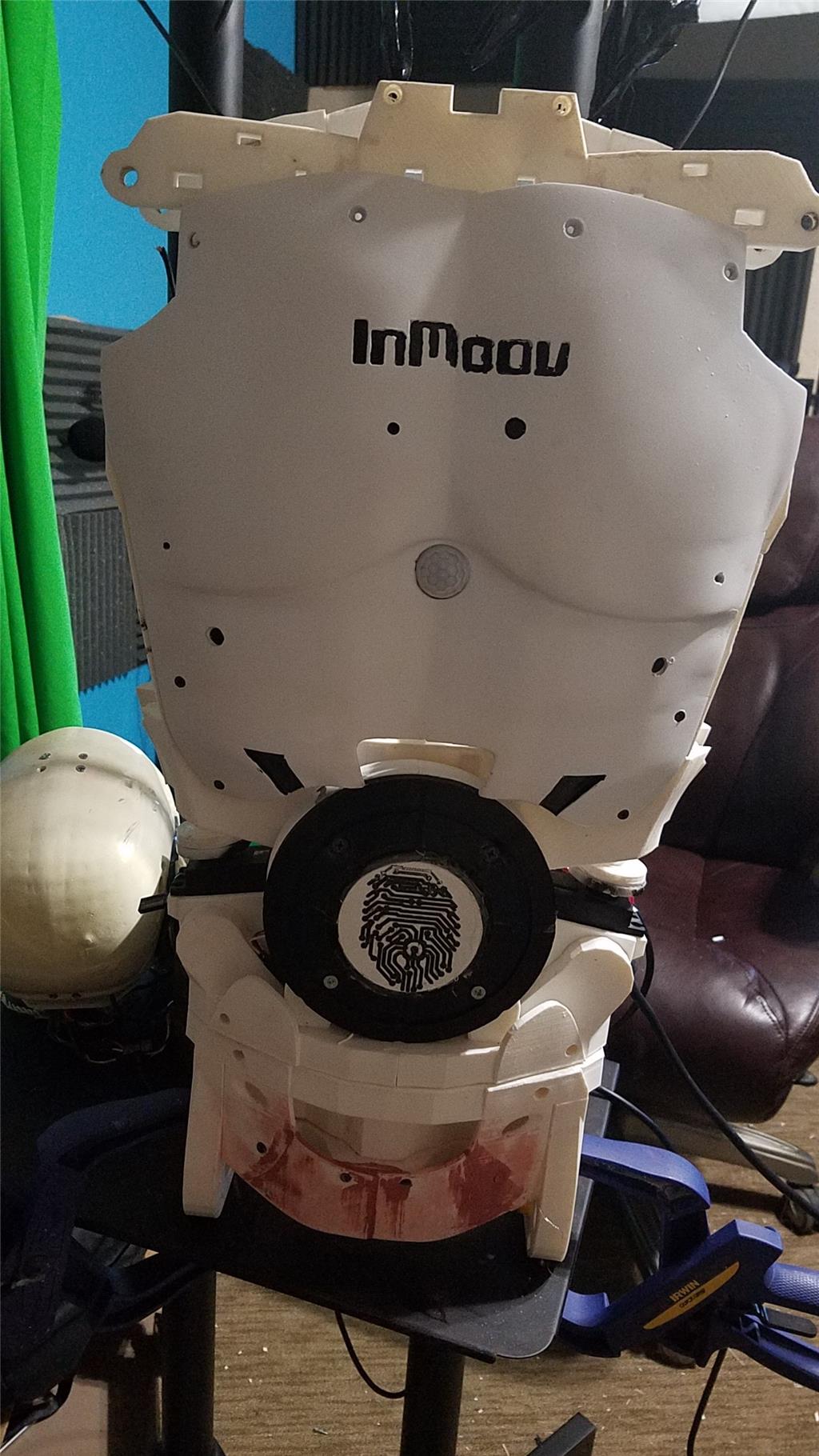


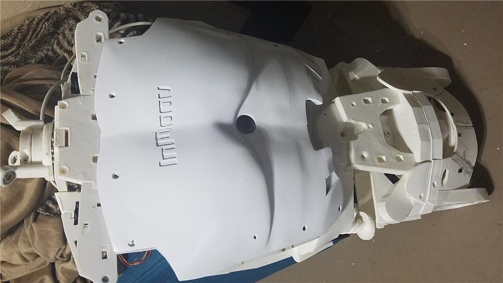
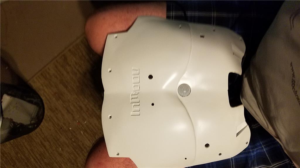
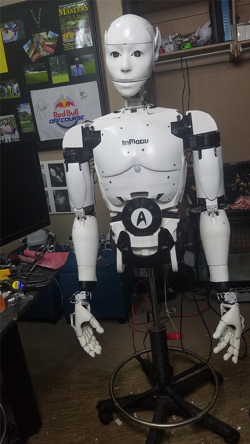
I have decided to start my InMoov project. I think I will call him Spock out of respect to Leonard Nimoy who passed away on the day that I started this project.
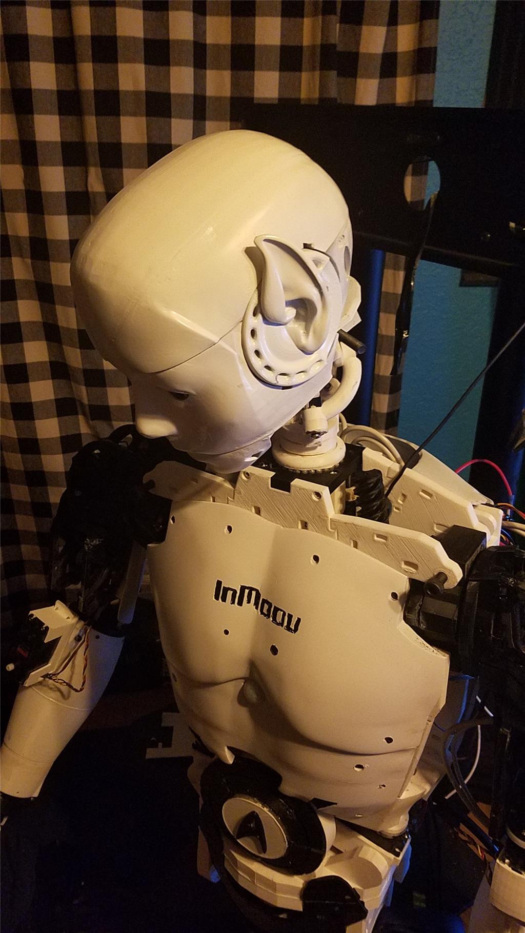
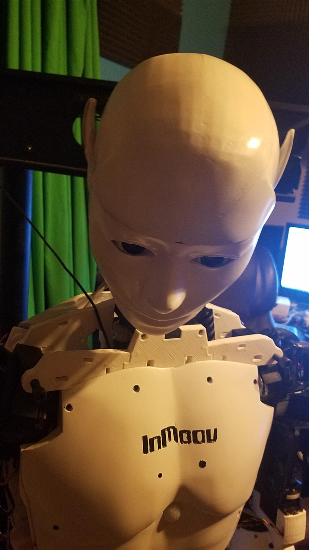
I am editing this post so as not to confuse people with the current configuration. I continue to update this post with the latest photos. If you are reading this for the first time, don't be confused. There have been a lot of changes to the InMoov over the past couple of years including starting over.
https://synthiam.com/Community/Questions/7398&page=21 Post 203 starts the rebuild of the InMoov.
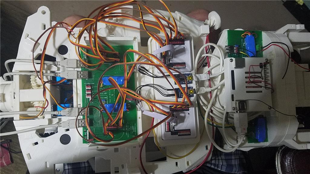
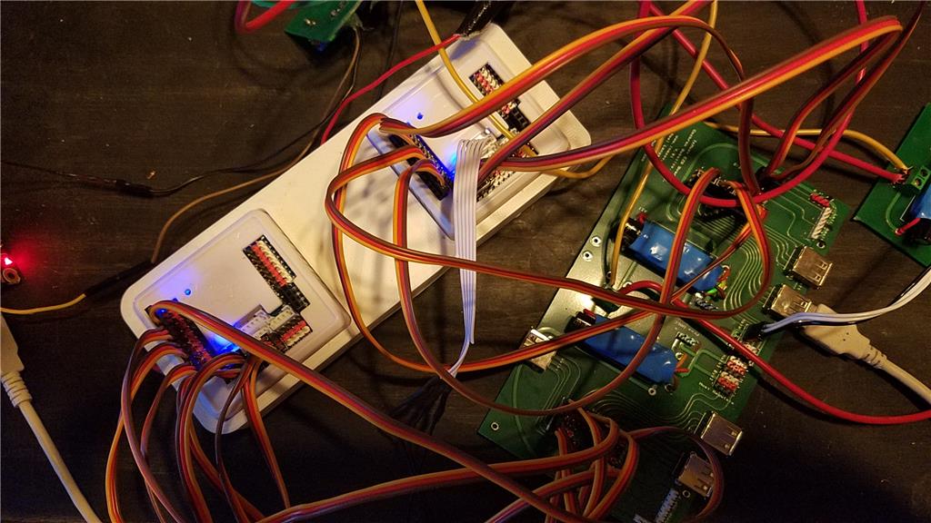
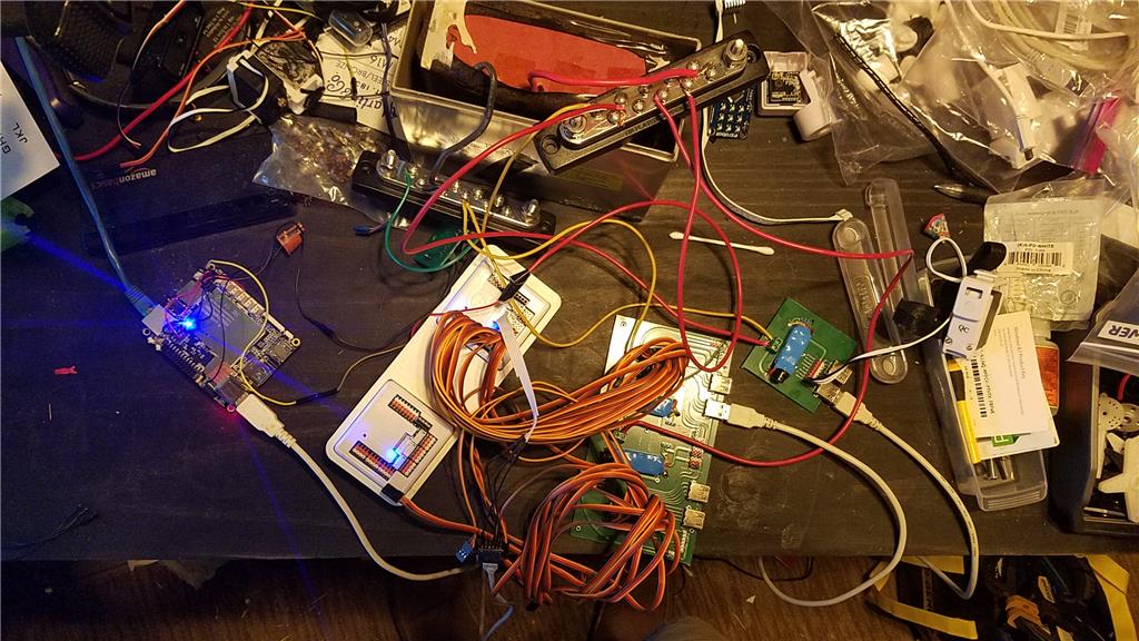
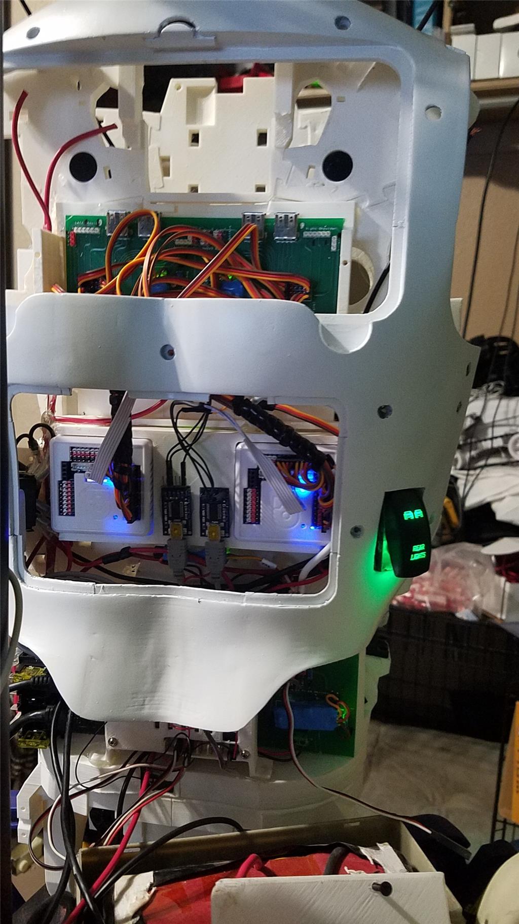
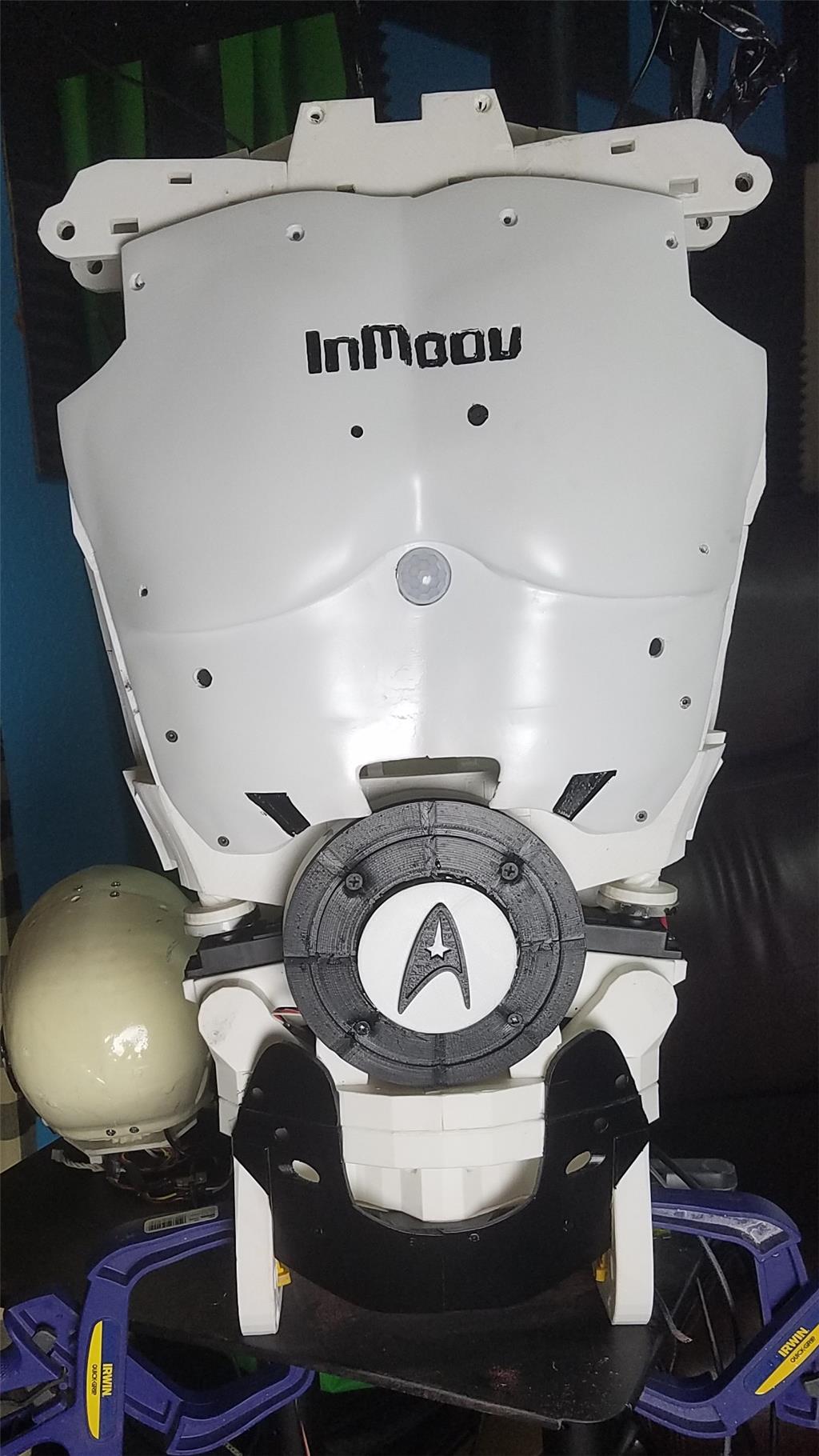
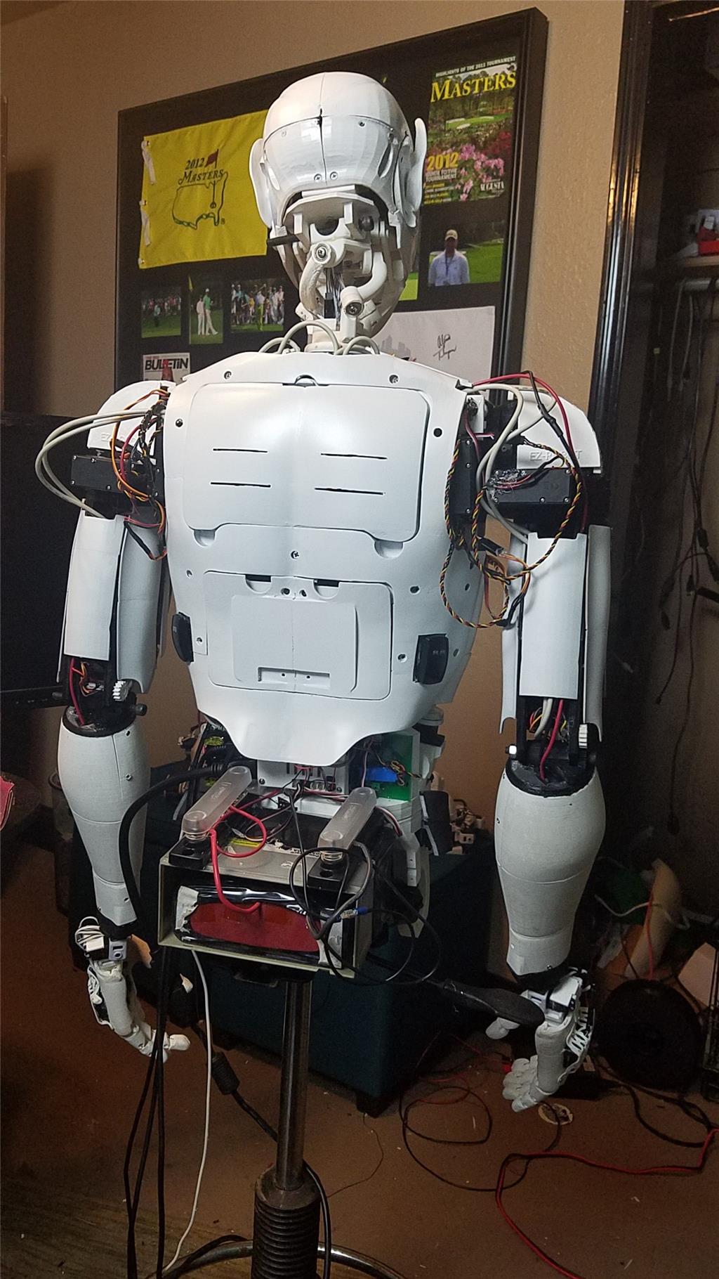
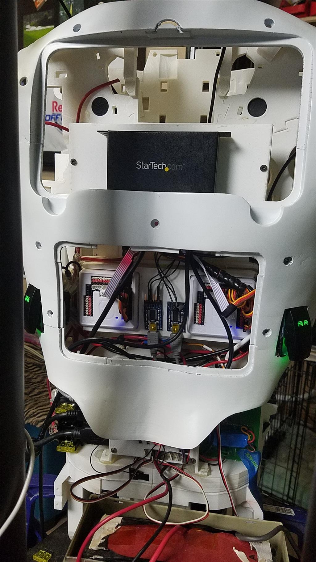
I have decided to use an onboard computer. I chose the Latte Panda due to it having an onboard arduino Leonardo and also because it uses little power.
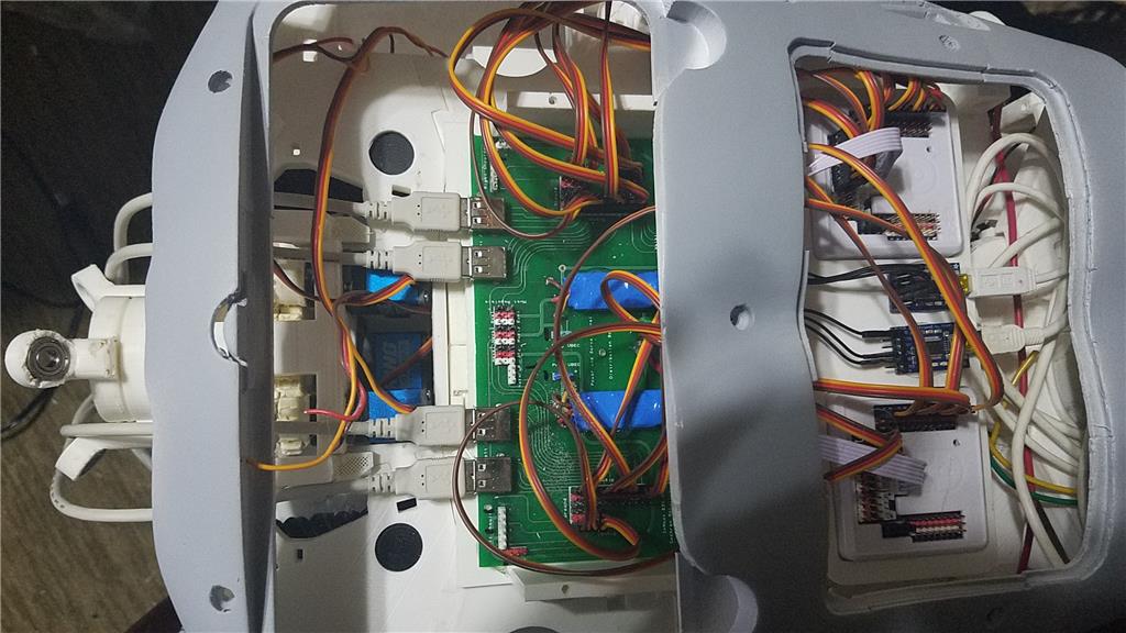
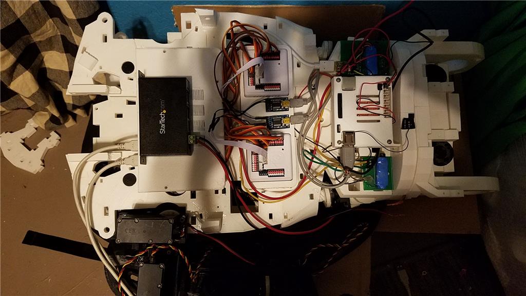
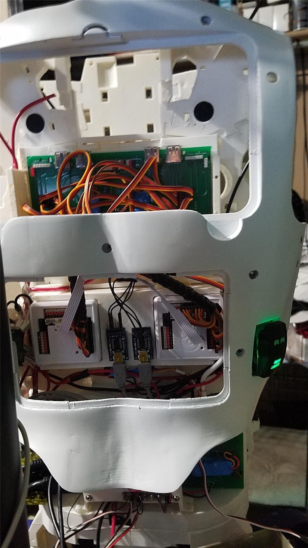
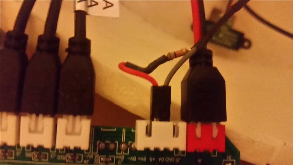
I used 2 EZ-B controllers connected via the camera port to Adafruit FTDI friend boards. This allows the Latte Panda to have a non-wifi dependent connection to the EZ-B's. I use a powered USB hub connected to the USB3 port on the Latte Panda to attach other items.
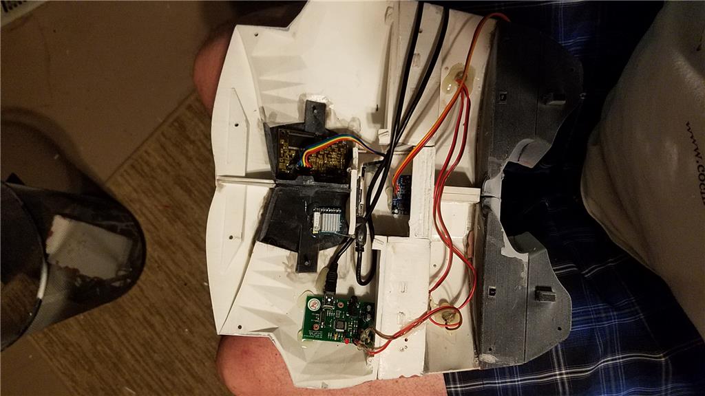
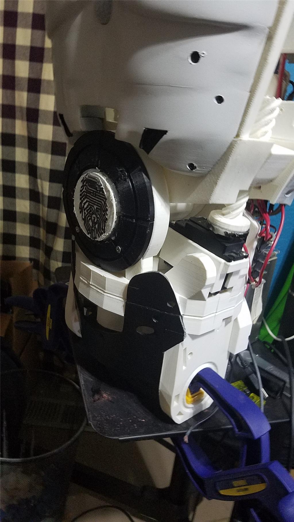
The Omron HVC-P is used to identify people, emotions, human bodies, hands, age and gender. It is attached to the Latte Panda via an FTDI friend which is then connected to the powered USB hub. It is mounted in the chest of the InMoov. I also use a 3 element microphone which is a MXL AC-404 microphone. It is disassembled and the board and microphone elements are mounted in the chest of the InMoov. This mic board is connected to the Latte Panda via a usb cable which is attached to the powered USB hub. There is a USB camera in the eye of the InMoov which is connected to the Latte Panda via the powered USB hub.
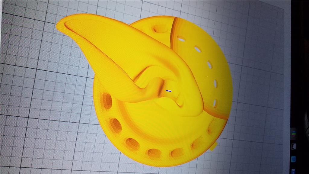
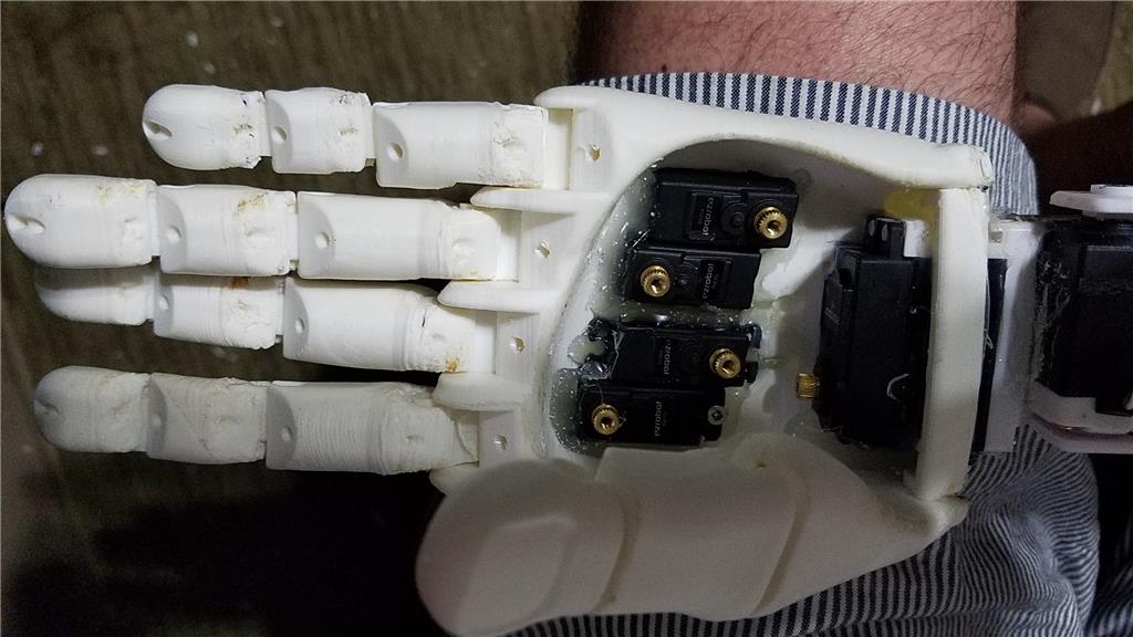
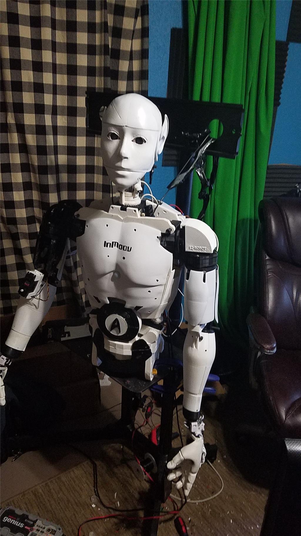
I chose to use the Flexy hand with the InMoov. The design is far more rugged than the original hand and works very well. There are 4 EZ-Robot Micro Servos in the palm of each hand which controls the main fingers. The thumb is controlled by an EZ-Robot HD servo. The wrist waves and uses an EZ-Robot HD servo to do this motion. I use the standard Rotational wrist.
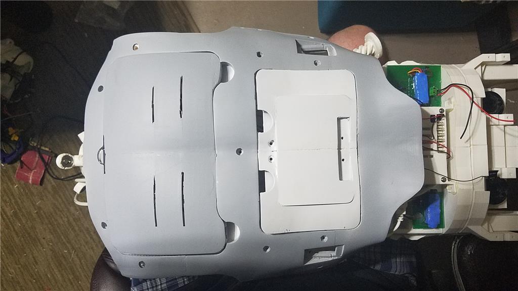
I have castle BEC's for power in the following locations set to the following voltages. Forearm's - 6.2 V - Controls fingers, wrist and elbows Custom power distribution board (2) set to 6.2 V controlling head, neck and Shoulder servos. EZ-B's - set to 6.1 V - it is mounted in the controller mounting plate and connects to the EZ-B fused power boards from a power base. Latte Panda - Set to 5.1 V and is mounted to the EZ-B controller mounting plate. Waist - set to 6.2 V and is mounted in the lower right side of the back. This provides power to the lean and pivot waist motors..
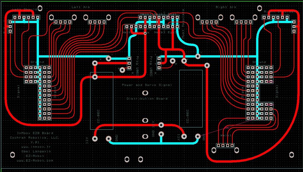
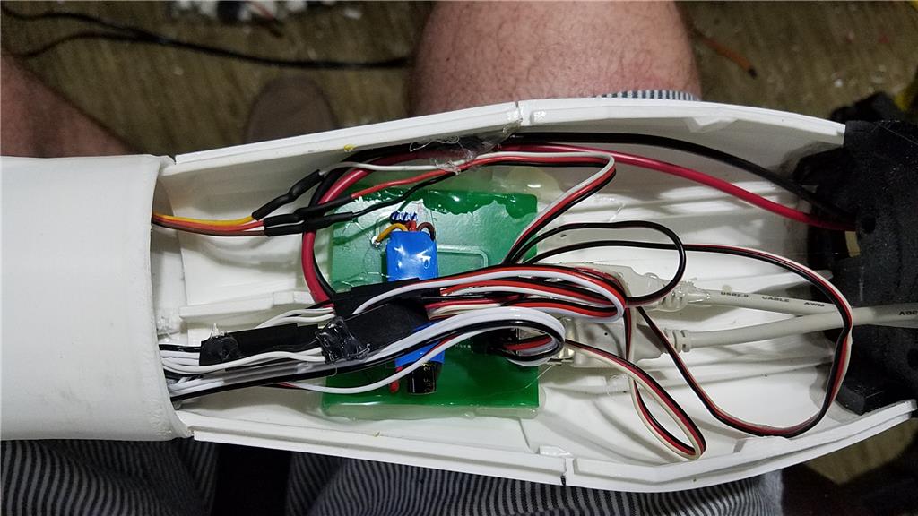
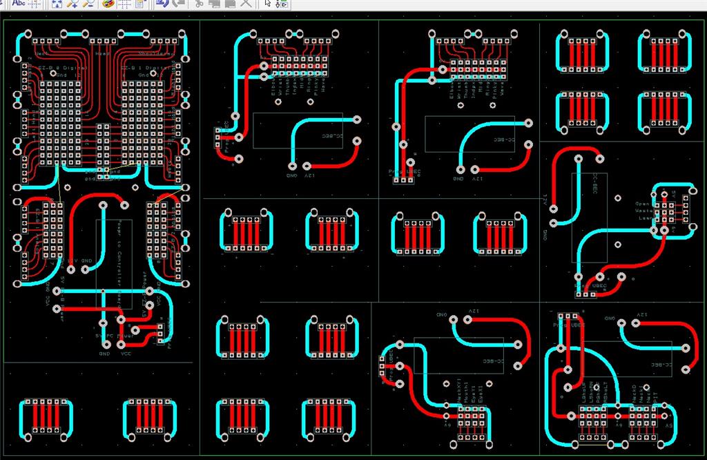
There are some custom power and signal distribution boards. These are in the forearms, lower back and in the upper back. The upper back or main board connects to these distribution points via USB cables to provide signal to the other boards for servos. The main board also has servo connector pins that are for the neck, head and shoulders. This allows the power to be distributed between multiple BEC's and also allows the servo signal cables to be shorter and more protected via the USB cables.
For power I use a LiFePo4 battery that is rated at 30 amps. It has the balanced charging circuit built into the battery and also has a low voltage shutoff built into the battery. This protects the battery and allows the battery to be charged with standard car chargers.
I put switches on the back on the InMoov which are rated at 20 amps at 12 volts. These are rocker switches that allow the user to pretty much slap the switch to turn it off. There are two of these switches. The servos for the elbows and fingers are on one switch. The latte panda, neck, shoulders, EZ-B's, waist motors and some lighting is on the other switch.
I also added a fuse block. This allows 20 amp fuses to be put in line to help protect things. The switches above drive the fuses for each of of the motors listed in that section.
-636348716348649435.jpg)

Discover more robots
Nomad's Adventurebot Cherry
Irobot58's Project F.R.E.D( Friendly Robotic Entertainment...

Hey Steve, thanks. I will get back to it before too long. I have another project that is going to consume my time. I should have what that project will be outlined tomorrow. I have a meeting with my investor and have to sign some paperwork to get my company finalized. Then there is the copyright and other paperwork that he will handle and the funding to start building the prototype for the other project. From there we need to figure out a lot of things like injection molding parts, suppliers for some parts and other fun stuff. I am sure that there will be some wait time involved in all of this (oh and I have to get my passport renewed). I have got to go visit DJ and discuss some things and all of that fun stuff. Anyway, during the wait time, I will work on the InMoov. There are some things that I have learned from working on him that I will carry over into the other project.
The idea of the base and how I was going to build that has been floating around in my head for a while. I think I have it figured out and just have to start the build of it. My wife started an upholstery business and spent some money so I agreed that I wouldn't spend until they got what they needed for the business. I think this has all been purchased (now just waiting for me to go pick all of it up and put it in their shop for them). My hope is that before too long, there will be funds to build the base. The good news is that they have already recovered the money that they have spent through selling some pieces that my wife had done. People seem to really like their work and they are already backed up with orders for about the next 5 months or so. I also have to write an application for their business (yet to be defined though). I think it will basically be to track jobs and job information from quotes. I am sure that they will have me turn it into a billing system and other things, but they haven't given me what they want it to do yet. They have asked me how long it would take to build. Because I never finished my Psychic Reader Advisor program from 20 years ago, I have no way of knowing. The funny thing is that the same thing always happens and is now happening from my wife. I am convinced that the question of "How long will it take you to build a completely undefined piece of software to make our lives easier" has been asked of every programmer on the face of the earth. I wish I had finished that program 20 years ago so that I would have had answers over the past 20 years
Anyway, there are a lot of other things going on, but the inmoov stares at me every day in my office. His neopixel ring has been running for a constant 8 days now. I am trying to see how long they last for the other project. He scares my wife at night while she is working on my computer. When it losses connection to my wifi for some reason and then reestablishes its connection, it says "I have lost connection to your network" and then "I have successfully connected to your network". I find this funny.
Exciting (and busy) times ahead for you then. I wish you luck with the new project sounds intriguing.
Steve.
Not that I am back on this project or anything, but I did want to share a piece. It has been discussed a couple of times to use an arduino to drive a set of car bumper sensors for a mobile base on a robot. Here is the Arduino code to make this work. It is not complete but it should be pretty easy to add additional distances as needed. This code will pass back information over a serial connection to the EZ-B for you to use. It will pass back "Object Detected - D at 18 inches" as an example. D would be port D on the bumper or parking sensor controller. A large majority of the work is done for you here. You will probably have to tweak it a bit to make it work for your particular needs.
I use an arduino mini pro (they cost a couple of bucks on ebay). I would buy the 5 mini's for $15.00 personally. Once you start incorporating them into your bot, you will find other things that you will want to do with them and extras are always a good thing.
These sensors detect out to about 6 feet pretty accurately. With a spin of your robot, you would be able to tell what is within 6 feet of your robot pretty easily. This code only goes out to 18 inches, but with some experimentation you can find the combination of bits that will measure further than 18 inches. The code below shows you how to combine these bits to calculate the distance on the arduino subsystem and pass back a meaningful string via serial that can be used by the EZ-B. This is designed to be a very quiet solution that won't flood the serial port on the EZ-B, or your robot application with constant bombarding of the same information.
Also, you could move some things to functions if you want. I left it linear for this as I wanted to make it as easy to follow as possible.
copy and paste inheritance got me there, script fixed for port D...
I would ezrobot connect with Arduino board to drive the servo motors. I think using the I2C protocol. For voltage compatibility problems, I think use a bidirectional I2C card Logic Level Converter. Have you ever realize this communication?
Yes, I use a bidirectional converter powered with 5v to the high side and 3.3 v to the low side. I use serial via the digital pins so it really isn't an issue anyway. This is a known issue with using 5v Arduino with Beagle bone, RPi or really any other primary controller.
Just ordered the car bumper sensor kit. Will let you know how things work out once arrived. Thanks for sharing your code with us
Sharing is caring
@Herr Ball,
There was a mistake in the code. I updated it to fix the issue. Let me know if you run into any issues.